Table of Contents
Advertisement
Advertisement
Table of Contents

Related Manuals for Safety Vision SV-LCD70RP


Summary of Contents for Safety Vision SV-LCD70RP
- Page 1 lcd rear vision monitor...
-
Page 2: Important Notices
Safety Vision reserves the right to amend the information in this document at any time without prior notice. This material is confidential and the property of Safety Vision. It is shared with your company for the sole purpose of helping you with the operation of the described equipment. -
Page 3: Table Of Contents
Table of Contents Front Panel Components Rear Panel Components Menu Navigation Function Menu Picture Menu Installation Location Installation Procedure Cleaning Appendix A Appendix B Appendix C Appendix D Returning the Unit for Service FCC Compliance Statement... -
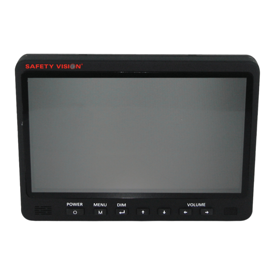
Page 4: Front Panel Components
Front Panel Components Power Button and Standby Light A red light indicates that the monitor is ON and in Standby mode. (Monitor power remains on until the vehicle ignition key is on the OFF position.) Menu Button This button initiates display of the main menu. After setting options in the menu, press the MENU button again to go back. -
Page 5: Rear Panel Components
Rear Panel Components Bracket Slot This slot accepts the adjustable mounting bracket. Input Cable Cameras and power and trigger wires are connected to this cable NOTE: Connect the camera(s) to the monitor before supplying power. -
Page 6: Menu Navigation
Menu Navigation To navigate through the menu, press the MENU button. Press the MENU button once to display the FUNCTION menu, and press it once more to display the PICTURE menu. Press the MENU button while the PICTURE menu is displayed to exit the menu. -
Page 7: Picture Menu
• TINT All adjustments can be set to values between 0 and 100. The factory default value for all adjustments is 50. Supplied Accessories The following accessories are supplied with the SV-LCD70RP monitor: • Adjustable mounting bracket • Screw kit •... -
Page 8: Installation Location
Installation Location The SV-LCD70RP monitor can be mounted on the ceiling or on the dashboard or console. Ceiling mount Ç Console or dashboard mount Ç... -
Page 9: Installation Procedure
Installation Procedure Select a suitable installation surface in a protected location that is within easy line-of-sight and easy reach of the operator. (For example, select a location that does not obstruct the operator’s view through the windshield, or of side- or rear-view mirrors.) Clean the installation surface thoroughly. -
Page 10: Appendix A
Celsius CA. SEL Camera Select Camera 1 Camera 2 Audio / Video Fahrenheit Liquid crystal display Millimeter NTSC National television Standards Committee Red, green, blue Return material autorization Safety Vision L.P. Thin-film transistor TRIG. Trigger Volt Volts direct current Volume... -
Page 11: Appendix B
Appendix B Specifications 7-inch LCD System NTSC/PAL Video System Auto Dimmer Selectable auto/manual OSD Controls Bright, Contrast, Color, Tint, CAM Distance, Dimmer, Language, Direction, Reset, Power Resolution 1440 (RGB) x 234 Impact Rating Internal Sync System 12 - 24 VDC Power Input 8 Watt Max. -
Page 12: Appendix C
Safety Vision website: www.safetyvision.com. Appendix D Troubleshooting Safety Vision, L.P. (“SV”) makes the following limited warranty, which is effec- tive at the time of the original end-user purchase. NOTE: Optional warranty products are available for all SV products... - Page 13 Customer’s Responsibility The above warranty is subject to the following conditions: • Customer must notify SV within 10 days of discovering the defective product or part and provide a description of the defect and complete information about the manner of its discovery. •...
-
Page 14: Returning The Unit For Service
Returning the Unit for Service To return the SV-LCD70RP unit for service: Call Technical Support at 800-880-8855. Speak to a Technical Support Representative. rma number and any additional special instructions. Obtain an Carefully pack the unit, including all defective parts and a note that includes the RMA Number and a detailed description of the issue experienced. -
Page 15: Fcc Compliance Statement
FCC Compliance Statement NOTE This device has been tested and found to comply with the limits for a Class A digital device, pursuant to part 15 of the FCC Rules. These limits are designed to provide reasonable protection against harmful interference when the equip- ment is operated in a commercial environment. - Page 16 CORPORATE HEADqUARTERS 6100 W. Sam Houston Pkwy. N. Houston, TX 77041-5113 Main: 713.896.6600 Toll Free: 800.880.8855 Fax: 713.896.6640 www.safetyvision.com 09/08...
Need help?
Do you have a question about the SV-LCD70RP and is the answer not in the manual?
Questions and answers