Table of Contents
Advertisement
Quick Links
ISP-9652/9602 User Manual
IEI Technology Corp.
MODEL:
MODEL:
ISP-9652/9602
ISP-9652/9602
MicroATX Socket P Motherboard for Intel® Core™2 Duo /
Celeron® M CPU, VGA, Four PCIe GbE LAN with dual-group
bypass function, Two PCIe GbE LAN, SATA 3.0 Gb/s, USB 2.0
and CompactFlash®, RoHS Compliant
Rev. 1.00 – 12 February, 2010
Rev. 1.00 – 12 February, 2010
User Manual
Page i
Advertisement
Chapters
Table of Contents

Related Manuals for IEI Technology ISP-9652/9602


Summary of Contents for IEI Technology ISP-9652/9602
-
Page 1: User Manual
ISP-9652/9602 User Manual IEI Technology Corp. MODEL: MODEL: ISP-9652/9602 ISP-9652/9602 MicroATX Socket P Motherboard for Intel® Core™2 Duo / Celeron® M CPU, VGA, Four PCIe GbE LAN with dual-group bypass function, Two PCIe GbE LAN, SATA 3.0 Gb/s, USB 2.0 and CompactFlash®, RoHS Compliant... - Page 2 ISP-9652/9602 User Manual Revision Date Version Changes 12 February, 2010 1.00 Initial release Page ii...
- Page 3 ISP-9652/9602 User Manual Copyright COPYRIGHT NOTICE The information in this document is subject to change without prior notice in order to improve reliability, design and function and does not represent a commitment on the part of the manufacturer. In no event will the manufacturer be liable for direct, indirect, special, incidental, or consequential damages arising out of the use or inability to use the product or documentation, even if advised of the possibility of such damages.
-
Page 4: Table Of Contents
ACKING 2.3.1 Optional Items....................10 3 CONNECTORS ......................12 3.1 P ..............13 ERIPHERAL NTERFACE ONNECTORS 3.1.1 ISP-9652/9602 Layout ..................13 3.1.2 Peripheral Interface Connectors ..............13 3.1.3 External Interface Panel Connectors............... 14 3.2 I ..............14 NTERNAL ERIPHERAL ONNECTORS 3.2.1 12V Power Connector.................. - Page 5 ISP-9652/9602 User Manual 3.3 E ......... 28 XTERNAL ERIPHERAL NTERFACE ONNECTOR ANEL 3.3.1 LAN Connectors....................28 3.3.2 USB Connectors....................29 4 INSTALLATION ......................31 4.1 A ..................32 STATIC RECAUTIONS 4.2 I ................32 NSTALLATION ONSIDERATIONS 4.2.1 Installation Notices ..................33 4.2.2 Installation Checklist ..................
- Page 6 ISP-9652/9602 User Manual 5.1 I ......................57 NTRODUCTION 5.1.1 Starting Setup....................57 5.1.2 Using Setup ...................... 57 5.1.3 Getting Help..................... 58 5.1.4 Unable to Reboot After Configuration Changes..........58 5.1.5 BIOS Menu Bar....................58 5.2 M ........................58 5.3 A .......................
- Page 7 ISP-9652/9602 User Manual E.1 H IPB P AZARDOUS ATERIALS ISCLOSURE ABLE FOR RODUCTS ERTIFIED AS HS C 2002/95/EC W ........11 OMPLIANT NDER ITHOUT ERCURY Page vii...
- Page 8 Figure 3-11: SPI Flash Connector Locations................26 Figure 3-12: USB Connector Pinout Locations .................27 Figure 3-13: VGA Connector .......................27 Figure 3-14: ISP-9652/9602 External Peripheral Interface Connector ........28 Figure 3-15: RJ-45 Ethernet Connector..................29 Figure 3-16: RJ-45 Ethernet Connector..................30 Figure 4-1: Make sure the CPU socket retention screw is unlocked ........36 Figure 4-2: Lock the CPU Socket Retention Screw..............37...
- Page 9 ISP-9652/9602 User Manual Figure 4-11: Single RS-232 Cable Installation ................49 Figure 4-12: SATA Power Drive Connection................49 Figure 4-13: Four Port USB Cable Connection................50 Figure 4-14: VGA Connector .......................51 Figure 4-15: LAN Connection ......................53 Figure 4-16: USB Connector......................54 Figure 4-17: Introduction Screen ....................55 Figure 4-18: Available Drivers .....................55...
- Page 10 ISP-9652/9602 User Manual List of Tables Table 1-1: Technical Specifications....................7 Table 3-1: Peripheral Interface Connectors ................14 Table 3-2: Rear Panel Connectors ....................14 Table 3-3: CPU 12V Power Connector Pinouts................15 Table 3-4: ATX Power Connector Pinouts .................16 Table 3-5: CompactFlash® Slot Pinouts ..................18 Table 3-6: +12V Fan Connector Pinouts..................19...
- Page 11 ISP-9652/9602 User Manual BIOS Menus BIOS Menu 1: Main ........................59 BIOS Menu 2: Advanced ......................61 BIOS Menu 3: CPU Configuration ....................61 BIOS Menu 4: IDE Configuration....................62 BIOS Menu 5: IDE Master and IDE Slave Configuration ............64 BIOS Menu 6: Super IO Configuration..................68 BIOS Menu 7: Hardware Health Configuration ................70...
- Page 12 ISP-9652/9602 User Manual Page xii...
-
Page 13: Introduction
ISP-9652/9602 User Manual Chapter Introduction Page 1... -
Page 14: Introduction
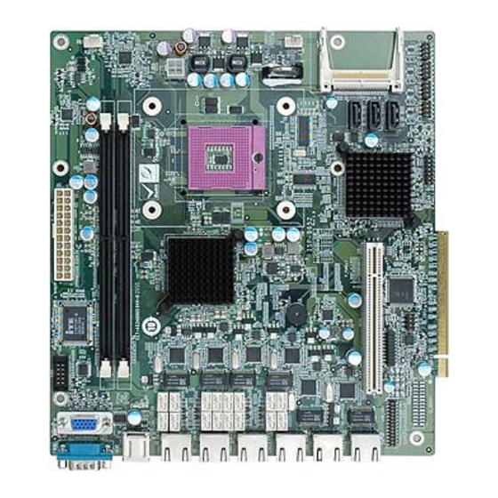
1.1 Introduction Figure 1-1: ISP-9652/9602 The ISP-9652/9602 MicroATX motherboard is a Socket P Intel® Core™2 Duo and Intel® Celeron® M processor platform. 45nm core and 65nm core processors are supported. Up to two 2.0 GB 667/533 MHz are supported by the Intel® GME965 graphics memory controller hub (GMCH) on the ISP-9652, while the Intel®... -
Page 15: Connectors
ISP-9652/9602 User Manual 1.2 Connectors The connectors on the ISP-9652/9602 are shown in the figure below. Figure 1-2: Connectors Page 3... -
Page 16: Dimensions
ISP-9652/9602 User Manual 1.3 Dimensions The dimensions of the board are listed below: Length: 220 mm Width: 244 mm Page 4... -
Page 17: Data Flow
ISP-9652/9602 User Manual Figure 1-3: ISP-9652/9602 Dimensions (mm) 1.4 Data Flow F igure 1-4 shows the data flow between the two on-board chipsets and other components installed on the motherboard and described in the following sections of this chapter. Figure 1-4: Data Flow Block Diagram... -
Page 18: Technical Specifications
ISP-9652/9602 User Manual 1.5 Technical Specifications ISP-9652/9602 technical specifications are listed in table below. Specification ISP-9652/9602 ISP-9602 MicroATX Form Factor Socket P Socket Socket P Intel® Core™2 Duo processor CPU Supported Socket P Intel® Celeron® M processor Front Side Bus... -
Page 19: Table 1-1: Technical Specifications
ISP-9652/9602 User Manual Specification ISP-9652/9602 ISP-9602 One VGA port Display Ethernet Six RJ-45 GbE ports Serial Ports One RS-232 Serial Port One RS-232 via internal box header USB 2.0/1.1 Two USB ports ports Eight USB via internal pin headers Storage CompactFlash®... -
Page 20: Unpacking
ISP-9652/9602 User Manual Chapter Unpacking Page 8... -
Page 21: Anti-Static Precautions
Only handle the edges of the PCB: Don't touch the surface of the motherboard. Hold the motherboard by the edges when handling. 2.2 Unpacking Precautions When the ISP-9652/9602 is unpacked, please do the following: Follow the antistatic guidelines above. Make sure the packing box is facing upwards when opening. -
Page 22: Optional Items
ISP-9652/9602 User Manual The ISP-9652/9602 is shipped with the following components: Quantity Item and Part Number Image ISP-9652/9602 motherboard SATA cable (P/N: 32000-062800-RS) Mini jumper pack (2.0mm) (P/N: 33100-000033-RS) Utility CD Quick Installation Guide 2.3.1 Optional Items The ISP-9652/9602 is shipped with the following components:... - Page 23 ISP-9652/9602 User Manual Single port RS-232 cable (P/N: 19800-000114-RS) Quad port USB cable (P/N: CB-USB14-RS) Page 11...
-
Page 24: Connectors
ISP-9652/9602 User Manual Chapter Connectors Page 12... -
Page 25: Peripheral Interface Connectors
ISP-9652/9602 User Manual 3.1 Peripheral Interface Connectors This chapter details all the jumpers and connectors. 3.1.1 ISP-9652/9602 Layout The figures below show all the connectors and jumpers. Figure 3-1: Connector and Jumper Locations 3.1.2 Peripheral Interface Connectors The table below lists all the connectors on the board. -
Page 26: External Interface Panel Connectors
USB_CO1 VGA port connector 15-pin female VGA1 Table 3-2: Rear Panel Connectors 3.2 Internal Peripheral Connectors The section describes all of the connectors on the ISP-9652/9602. 3.2.1 12V Power Connector CN Label: CPU12V1 CN Type: 4-pin Molex connector (2x2) CN Location:... -
Page 27: Atx Power Connector
ISP-9652/9602 User Manual The connector supports the 12V power supply. Figure 3-2: CPU 12V Power Connector Location PIN NO. DESCRIPTION PIN NO. DESCRIPTION +12V +12V Table 3-3: CPU 12V Power Connector Pinouts 3.2.2 ATX Power Connector CN Label: ATX1 CN Type:... -
Page 28: Compactflash® Slot
ISP-9652/9602 User Manual Figure 3-3: ATX Power Connector Pinout Locations Description Description +3.3 V +3.3 V +3.3 V -12 V +5 V PS-ON +5 V PW-OK -5 V +VCC5SB +5 V FP22 +5 V Table 3-4: ATX Power Connector Pinouts 3.2.3 CompactFlash®... -
Page 29: Figure 3-4: Compactflash® Slot Location
ISP-9652/9602 User Manual Figure 3-4: CompactFlash® Slot Location Description Description GROUND VCC-IN CHECK1 DATA 3 DATA 11 DATA 4 DATA 12 DATA 5 DATA 13 DATA 6 DATA 14 DATA 7 DATA 15 HDC_CS0# HDC_CS1 GROUND IOR# IOW# VCC_COM IRQ15... -
Page 30: Fan Connectors
ISP-9652/9602 User Manual Description Description HDD_ACTIVE# DATA 0 66DET DATA 1 DATA 8 DATA 2 DATA 9 DATA 10 VCC-IN CHECK2 GROUND Table 3-5: CompactFlash® Slot Pinouts 3.2.4 Fan Connectors CN Label: CPU_FAN1 and SYS_FAN1 CN Type: 4-pin wafer (1x4) -
Page 31: Front Panel Connector
ISP-9652/9602 User Manual PIN NO. DESCRIPTION +12V DETECT CONTROL Table 3-6: +12V Fan Connector Pinouts 3.2.5 Front Panel Connector CN Label: F_PANEL1 CN Type: 14-pin header (2x7) CN Location: See Figure 3-6 CN Pinouts: See Table 3-7 The front panel connector connects to external switches and indicators to monitor and controls the motherboard. -
Page 32: Lan Led Connector
ISP-9652/9602 User Manual FUNCTION DESCRIPTION FUNCTION DESCRIPTION Power LED Speaker Power Button PWRBT- Speaker Reset HDD LED IDELED Reset- HDLED- Table 3-7: Front Panel Connector Pinouts 3.2.6 LAN LED Connector CN Label: LAN_LED1 CN Type: 26-pin header (2x13) CN Location:... -
Page 33: Pci Slot
ISP-9652/9602 User Manual Description Description CN_L1_LINK_ACT# CN_L1_LED CN_L1_100# CN_L1_1000# CN_L2_LINK_ACT# CN_L2_LED CN_L2_100# CN_L2_1000# CN_L3_LINK_ACT# CN_L3_LED CN_L3_100# CN_L3_1000# CN_L4_LINK_ACT# CN_L4_LED CN_L4_100# CN_L4_1000# CN_L5_LINK_ACT# CN_L5_LED CN_L5_100# CN_L5_1000# CN_L6_LINK_ACT# CN_L6_LED CN_L6_100# CN_L6_1000# Table 3-8: LAN LED Connector Pinouts 3.2.7 PCI Slot CN Label:... - Page 34 ISP-9652/9602 User Manual PIN NO. DESCRIPTION PIN NO. DESCRIPTION TRST -12 V +12 V +5 V +5 V INTA +5 V INTC INTB +5 V INTD RESERVED3 PRSNT1 +5 V RESERVED1 RESERVED4 PRSNT2 3.3 V_AUX RESERVED2 +5 V +5 V...
-
Page 35: Table 3-9: Pci Slot
ISP-9652/9602 User Manual PIN NO. DESCRIPTION PIN NO. DESCRIPTION +3.3 V C/BE2 FRAME IRDY TRDY +3.3 V DEVSEL STOP +3.3 V LOCK SDONE PERR +3.3 V SERR +3.3 V AD15 C/BE1 +3.3 V AD14 AD13 AD11 AD12 AD10 C/BE0 +3.3 V +3.3 V... -
Page 36: Sata Drive Connectors
ISP-9652/9602 User Manual 3.2.8 SATA Drive Connectors CN Label: SATA1, SATA2 and SATA3 7-pin SATA 3Gb/s drive connectors CN Type: CN Location: F igure 3-9 CN Pinouts: T able 3-10 The three SATA 3Gb/s drive connectors are each connected to a SATA 3Gb/s drive. The drives transfer data at speeds as high as 3.0 Gb/s. -
Page 37: Serial Port Connector
ISP-9652/9602 User Manual 3.2.9 Serial Port Connector CN Label: COM2 10-pin header (2x5) CN Type: CN Location: See Figure 3-10 CN Pinouts: See Table 3-11 This connector provides RS-232 communications. Figure 3-10: Serial Port Connector Location PIN NO. DESCRIPTION PIN NO. -
Page 38: Usb Connectors
ISP-9652/9602 User Manual Figure 3-11: SPI Flash Connector Locations DESCRIPTION DESCRIPTION CLOCK Table 3-12: SPI Flash Connector Pinouts 3.2.11 USB Connectors CN Label: USB23, USB45, USB67 and USB68 8-pin header (2x4) CN Type: CN Location: See Figure 3-12 CN Pinouts: See Table 3-17 The USB connectors connect to USB devices. -
Page 39: Vga Connector
3.2.12 VGA Connector CN Label: VGA1 CN Type: 15-pin Female CN Location: F igure 3-13 CN Pinouts: T able 3-14 The ISP-9652/9602 has a single 15-pin female connector for connectivity to standard display devices. Figure 3-13: VGA Connector Page 27... -
Page 40: External Peripheral Interface Connector Panel
GROUND Table 3-14: VGA Connector Pinouts 3.3 External Peripheral Interface Connector Panel F igure 3-14 shows the ISP-9652/9602 external peripheral interface connector (EPIC) panel. The ISP-9652/9602 EPIC panel consists of the following: 6 x RJ-45 LAN connectors 2 x USB connectors... -
Page 41: Usb Connectors
ISP-9652/9602 User Manual The ISP-9652/9602 is equipped with six built-in RJ-45 Ethernet controllers. The controllers connect to the LAN through six RJ-45 LAN connectors. There are two LEDs on the connector indicating the status of LAN. The pin assignments are listed in the following... -
Page 42: Figure 3-16: Rj-45 Ethernet Connector
ISP-9652/9602 User Manual The ISP-9652/9602 has two external USB 2.0 ports. The ports connect to both USB 2.0 and USB 1.1 devices. PIN NO. DESCRIPTION DATA- DATA+ GROUND Table 3-17: USB Port Connector Pinouts Figure 3-16: RJ-45 Ethernet Connector Page 30... -
Page 43: Installation
ISP-9652/9602 User Manual Chapter Installation Page 31... -
Page 44: Anti-Static Precautions
Electrostatic discharge (ESD) can cause serious damage to electronic components, including the ISP-9652/9602. Dry climates are especially susceptible to ESD. It is therefore critical that whenever the ISP-9652/9602 or any other electrical component is handled, the following anti-static precautions are strictly adhered to. -
Page 45: Installation Notices
4.2.1 Installation Notices Warning: The installation instructions described in this manual should be carefully followed in order to prevent damage to the ISP-9652/9602, its components and injury to the user. Before and during the installation please DO the following: Read the user manual: The user manual provides a complete description of the ISP-9652/9602 installation instructions and configuration options. -
Page 46: Installation Checklist
USB devices 4.3 Unpacking When the ISP-9652/9602 is unpacked, please check all the unpacking list items listed in Chapter 3 are present. If any of the unpacking list items are not available please contact the ISP-9652/9602 reseller/vendor where the ISP-9652/9602 was purchased or contact an IEI sales representative. -
Page 47: Cpu, Cpu Cooling Kit And Dimm Installation
Running a CPU without a cooling kit may also result in injury to the user. The CPU, CPU cooling kit and DIMM are the most critical components of the ISP-9652/9602. If one of these component is not installed the ISP-9652/9602 cannot run. 4.4.1 Socket P CPU Installation WARNING: CPUs are expensive and sensitive components. -
Page 48: Figure 4-1: Make Sure The Cpu Socket Retention Screw Is Unlocked
ISP-9652/9602 User Manual WARNING: When handling the CPU, only hold it on the sides. DO NOT touch the pins at the bottom of the CPU. Step 1: Unlock the CPU retention screw. When shipped, the retention screw of the CPU socket should be in the unlocked position. If it is not in the unlocked position, use a screwdriver to unlock the screw. -
Page 49: Socket P Cooling Kit Installation
ISP-9652/9602 User Manual Step 5: Align the CPU pins. Carefully align the CPU pins with the holes in the CPU socket. Step 6: Insert the CPU. Gently insert the CPU into the socket. If the CPU pins are properly aligned, the CPU should slide into the CPU socket smoothly. -
Page 50: Dimm Installation
Step 11: Connect the fan cable. Connect the cooling kit fan cable to the fan connector on the ISP-9652/9602. Carefully route the cable and avoid heat generating chips and fan blades.Step 0: 4.4.3 DIMM Installation To install a DIMM module, please follow the steps below and refer to Figure 4-4. -
Page 51: Figure 4-4: Dimm Installation
ISP-9652/9602 User Manual Figure 4-4: DIMM Installation Step 1: Open the DIMM socket handles. Open the two handles outwards as far as they can. See Figure 4-4. Step 2: Align the DIMM with the socket. Align the DIMM so the notch on the memory lines up with the notch on the memory socket. -
Page 52: Jumper Settings
Jumper Location: F igure 4-5 If the ISP-9652/9602 fails to boot due to improper BIOS settings, the clear CMOS jumper clears the CMOS data and resets the system BIOS information. To do this, use the jumper cap to close pins 2 and 3 for a few seconds then reinstall the jumper clip back to pins 1 and 2. -
Page 53: Embedded Controller Function Settings
ISP-9652/9602 User Manual If the “CMOS Settings Wrong” message is displayed during the boot up process, the fault may be corrected by pressing the F1 to enter the CMOS Setup menu. Do one of the following: Enter the correct CMOS setting Load Optimal Defaults Load Failsafe Defaults. -
Page 54: Smbus Slave Address (Smb_Id)
ISP-9652/9602 User Manual The Embedded Controller Function Settings jumper controls the LAN Network Bypass MCU functions. Four functions are controlled by the jumper: SMB_ID, HW MCU Enable, ACK Count, and Bypass Function. The settings for these functions are described in the following subsections. -
Page 55: Ack Count
ISP-9652/9602 User Manual 4.5.2.3 ACK Count To set the countdown interval for SMBUS monitoring use the following jumper settings. Interval Pin No. 9 - 10 Pin No. 11 - 12 Pin No. 13 - 14 Pin No. 15 - 16... -
Page 56: Figure 4-6: Lan Bypass Mode Behavior
ISP-9652/9602 User Manual Figure 4-6: LAN Bypass Mode Behavior Use following jumper settings to enable or disable the LAN sleep bypass function. Bypass Function Pin No. 1 - 2 Bypass mode Short Normal mode Open Table 4-6: HW MCU Enable Jumper Settings The location of the Embedded Controller Function Settings jumper is shown in Figure 4-7 below. -
Page 57: Chassis Installation
The ISP-9652/9602 must be installed in a chassis with ventilation holes on the sides allowing airflow to travel through the heat sink surface. In a system with an individual power supply unit, the cooling fan of a power supply can also help generate airflow through the board surface. -
Page 58: Cpu Power Connection
ISP-9652/9602. WARNING: Disconnect the power supply power cord from its AC power source to prevent a sudden power surge to the ISP-9652/9602. Step 5: Locate the power cable. The power cable is shown in the packing list in Chapter 3. -
Page 59: Sata Drive Connection
ISP-9652/9602 User Manual Figure 4-9: Connect Power Cable to Power Supply 4.7.2 SATA Drive Connection The ISP-9652/9602 is shipped with three SATA drive cables. To connect the SATA drives to the connectors, please follow the steps below. Step 8: Locate the connectors. The locations of the SATA drive connectors are shown in Chapter 3. -
Page 60: Single Rs-232 Cable (W/O Bracket)
ISP-9652/9602 User Manual Figure 4-10: SATA Drive Cable Connection Step 10: Connect the cable to the SATA disk. Connect the connector on the other end of the cable to the connector at the back of the SATA drive. See F igure 4-12. -
Page 61: Figure 4-11: Single Rs-232 Cable Installation
ISP-9652/9602 User Manual Figure 4-11: Single RS-232 Cable Installation Step 13: Secure the bracket. The single RS-232 connector has two retention screws that must be secured to a chassis or bracket. Step 14: Connect the serial device. Once the single RS-232 connector is connected to a chassis or bracket, a serial communications device can be connected to the system. -
Page 62: Usb Cable (Four Port)
If the USB pins are not properly aligned, the USB device can burn out. Step 2: Align the connectors. Each cable has two connectors. Correctly align pin 1on each cable connector with pin 1 on the ISP-9652/9602 USB connectors. Step 3: Insert the cable connectors. Once the cable connectors are properly aligned with the USB connectors on the ISP-9652/9602, connect the cable connectors to the on-board connectors. -
Page 63: Vga Monitor Connection
0: 4.7.5 VGA Monitor Connection The ISP-9652/9602 has a single onboard female DB-15 connector. The DB-15 connector is connected to a CRT or VGA monitor. To connect a monitor to the ISP-9652/9602, please follow the instructions below. Step 1: Locate the female DB-15 connector. -
Page 64: External Peripheral Interface Connection
USB devices VGA monitors To install these devices, connect the corresponding cable connector from the actual device to the corresponding ISP-9652/9602 external peripheral interface connector making sure the pins are properly aligned. 4.8.1 LAN Connection There are six external RJ-45 LAN connectors. The RJ-45 connectors enable connection to an external network. -
Page 65: Usb Connection (Dual Connector)
ISP-9652/9602 User Manual Figure 4-15: LAN Connection Step 3: Insert the LAN cable RJ-45 connector. Once aligned, gently insert the LAN cable RJ-45 connector into the onboard RJ-45 connector. Step 0: 4.8.2 USB Connection (Dual Connector) The external USB Series "A" receptacle connectors provide easier and quicker access to external USB devices. -
Page 66: Software Installation
ISP-9652/9602 User Manual Figure 4-16: USB Connector 4.9 Software Installation All the drivers for the ISP-9652/9602 are on the CD that came with the system. To install the drivers, please follow the steps below. Step 3: Insert the CD into a CD drive connected to the system. -
Page 67: Figure 4-17: Introduction Screen
ISP-9652/9602 User Manual Figure 4-17: Introduction Screen Step 5: Click ISP-9652/9602. Step 6: A new screen with a list of available drivers appears (Figure 4-18). Figure 4-18: Available Drivers Step 7: Install all of the necessary drivers in this menu. -
Page 68: Bios Screens
ISP-9652/9602 User Manual Chapter BIOS Screens Page 56... -
Page 69: Introduction
ISP-9652/9602 User Manual 5.1 Introduction The BIOS is programmed onto the BIOS chip. The BIOS setup program allows changes to certain system settings. This chapter outlines the options that can be changed. 5.1.1 Starting Setup The AMI BIOS is activated when the computer is turned on. The setup program can be activated in one of two ways. -
Page 70: Getting Help
ISP-9652/9602 User Manual Function F2 /F3 key Change color from total 16 colors. F2 to select color forward. F10 key Save all the CMOS changes, only for Main Menu Table 5-1: BIOS Navigation Keys 5.1.3 Getting Help When F1 is pressed a small help window describing the appropriate keys to use and the possible selections for the highlighted item appears. -
Page 71: Bios Menu 1: Main
ISP-9652/9602 User Manual BIOS SETUP UTILITY Main Advanced PCIPNP Boot Security Chipset Power Exit System Overview Use [ENTER], [TAB] or ⎯⎯⎯⎯⎯⎯⎯⎯⎯⎯⎯⎯⎯⎯⎯⎯⎯⎯⎯⎯⎯⎯⎯⎯⎯⎯⎯⎯⎯⎯⎯ [SHIFT-TAB] to select a field. AMIBIOS Version :08.00.14 Use [+] or [-] to Build Date :11/09/09 configure system time. -
Page 72: Advanced
ISP-9652/9602 User Manual System Time [xx:xx:xx] Use the System Time option to set the system time. Manually enter the hours, minutes and seconds. System Date [xx/xx/xx] Use the System Date option to set the system date. Manually enter the day, month and year. -
Page 73: Cpu Configuration
ISP-9652/9602 User Manual BIOS SETUP UTILITY Main Advanced PCIPNP Boot Security Chipset Power Exit Advanced Settings Configure CPU ⎯⎯⎯⎯⎯⎯⎯⎯⎯⎯⎯⎯⎯⎯⎯⎯⎯⎯⎯⎯⎯⎯⎯⎯⎯⎯⎯⎯⎯⎯⎯ WARNING: Setting wrong values in below sections may cause system to malfunction > CPU Configuration > IDE Configuration > SuperIO Configuration >... -
Page 74: Ide Configuration
ISP-9652/9602 User Manual Frequency: Lists the CPU processing speed FSB Speed: Lists the FSB speed Cache L1: Lists the CPU L1 cache size Cache L2: Lists the CPU L2 cache size 5.3.2 IDE Configuration Use the IDE Configuration menu (BIOS Menu 4) to change and/or set the configuration of the IDE devices installed in the system. -
Page 75: Ide Master, Ide Slave
ISP-9652/9602 User Manual Enhanced Configures the on-board ATA/IDE controller to be in Enhanced mode. In this mode, IDE channels and SATA channels are separated. This mode supports up to 6 storage devices. Some legacy OS do not support this mode. -
Page 76: Bios Menu 5: Ide Master And Ide Slave Configuration
ISP-9652/9602 User Manual BIOS SETUP UTILITY Main Advanced PCIPNP Boot Security Chipset Power Exit Primary IDE Master Select the type of device ⎯⎯⎯⎯⎯⎯⎯⎯⎯⎯⎯⎯⎯⎯⎯⎯⎯⎯⎯⎯⎯⎯⎯⎯⎯⎯⎯⎯⎯⎯⎯ connected to the system Device :Not Detected Type [Auto] LBA/Large Mode [Auto] Block (Multi-Sector Transfer) [Auto] Select Screen... -
Page 77: Type [Auto]
ISP-9652/9602 User Manual 32Bit Data Transfer: Enables 32-bit data transfer. Type [Auto] Use the Type BIOS option select the type of device the AMIBIOS attempts to boot from after the Power-On Self-Test (POST) is complete. Not Installed BIOS is prevented from searching for an IDE disk drive on the specified channel. -
Page 78: Block (Multi Sector Transfer) [Auto]
ISP-9652/9602 User Manual Block (Multi Sector Transfer) [Auto] Use the Block (Multi Sector Transfer) to disable or enable BIOS to auto detect if the device supports multi-sector transfers. Disabled BIOS is prevented from using Multi-Sector Transfer on the specified channel. The data to and from the device occurs one sector at a time. - Page 79 ISP-9652/9602 User Manual Auto BIOS auto detects the DMA mode. Use this value if the IDE EFAULT disk drive support cannot be determined. Single Word DMA mode 0 selected with a maximum data SWDMA0 transfer rate of 2.1 MB/s SWDMA1 Single Word DMA mode 1 selected with a maximum data transfer rate of 4.2 MB/s...
-
Page 80: Super Io Configuration
ISP-9652/9602 User Manual S.M.A.R.T [Auto] Use the S.M.A.R.T option to auto-detect, disable or enable Self-Monitoring Analysis and Reporting Technology (SMART) on the drive on the specified channel. S.M.A.R.T predicts impending drive failures. The S.M.A.R.T BIOS option enables or disables this function. -
Page 81: Serial Port1 Address [3E8]
ISP-9652/9602 User Manual Serial Port1 Address [3E8] Use the Serial Port1 Address option to select the Serial Port 1 base address. No base address is assigned to Serial Port 1 Disabled 3F8/IRQ4 Serial Port 1 I/O port address is 3F8 and the interrupt... -
Page 82: Hardware Health Configuration
ISP-9652/9602 User Manual 5.3.4 Hardware Health Configuration The Hardware Health Configuration menu (BIOS Menu 7) shows the operating temperature, fan speeds and system voltages. BIOS SETUP UTILITY Main Advanced PCIPNP Boot Security Chipset Power Exit Hardware Health Event Monitoring CPU_FAN1 Mode Setting [Automatic Mode] CPU Temp. -
Page 83: Temp. Limit Of Off [000]
ISP-9652/9602 User Manual Automatic mode The fan adjusts its speed using these settings: Temp. Limit of OFF Temp. Limit of Start Fan Start PWM Slope PWM 1 PWM Manual mode The fan spins at the speed set in: Fan PWM control Temp. -
Page 84: Slope Pwm [1 Pwm]
ISP-9652/9602 User Manual PWM Maximum Mode: 127 Slope PWM [1 PWM] A bigger value will increase the fan speed in big amounts. A smaller value will increase the speed more gradually. 0 PWM 1 PWM 2 PWM 4 PWM 8 PWM... -
Page 85: Remote Access Configuration
ISP-9652/9602 User Manual System Temperature Fan Speeds: CPU_Fan1 Speed SYS_Fan2 Speed Voltages: CPU Core +1.05V +3.30V +5.00V +1.25V +1.5V +1.8V 5VSB VBAT 5.3.5 Remote Access Configuration Use the Remote Access Configuration menu (BIOS Menu 8) to configure remote access parameters. The Remote Access Configuration is an AMIBIOS feature and allows a remote host running a terminal program to display and configure the BIOS settings. -
Page 86: Remote Access [Disabled]
ISP-9652/9602 User Manual Remote Access [Disabled] Use the Remote Access option to enable or disable access to the remote functionalities of the system. Disabled Remote access is disabled. EFAULT Remote access configuration options shown below Enabled appear: Serial Port Number... -
Page 87: Usb Configuration
ISP-9652/9602 User Manual 38400 8,n,1 19200 8,n,1 09600 8,n,1 NOTE: Identical baud rate setting musts be set on the host (a management computer running a terminal software) and the slave Redirection After BIOS POST [Always] Use the Redirection After BIOS POST option to specify when console redirection should occur. -
Page 88: Bios Menu 9: Usb Configuration
ISP-9652/9602 User Manual BIOS SETUP UTILITY Main Advanced PCIPNP Boot Security Chipset Power Exit USB Configuration Enables USB host ⎯⎯⎯⎯⎯⎯⎯⎯⎯⎯⎯⎯⎯⎯⎯⎯⎯⎯⎯⎯⎯⎯⎯⎯⎯⎯⎯⎯⎯⎯⎯ controllers Module Version – 2.24.3-13.4 USB Devices Enabled: None Select Screen USB Functions [Enabled] ↑ ↓ USB 2.0 Controller [Enabled]... -
Page 89: Power Configuration
ISP-9652/9602 User Manual Legacy USB Support [Enabled] Use the Legacy USB Support BIOS option to enable USB mouse and USB keyboard support. Normally if this option is not enabled, any attached USB mouse or USB keyboard does not become available until a USB compatible operating system is fully booted with all USB drivers loaded. -
Page 90: Bios Menu 10: Apm Configuration
ISP-9652/9602 User Manual BIOS SETUP UTILITY Main Advanced PCIPNP Boot Security Chipset Power Exit APM Configuration Go into On/Off, or ⎯⎯⎯⎯⎯⎯⎯⎯⎯⎯⎯⎯⎯⎯⎯⎯⎯⎯⎯⎯⎯⎯⎯⎯⎯⎯⎯⎯⎯⎯⎯ Suspend when Power button is pressed Power Button Mode [On/Off] Restore on AC Power Loss [Power On] Advanced Resume Event Controls... -
Page 91: Resume On Ring [Disabled]
ISP-9652/9602 User Manual Resume on Ring [Disabled] Use the Resume on Ring BIOS option to enable activity on the RI (ring in) modem line to rouse the system from a suspend or standby state. That is, the system will be roused by an incoming call on a modem. -
Page 92: Pci/Pnp
ISP-9652/9602 User Manual 5.4 PCI/PnP Use the PCI/PnP menu (BIOS Menu 11) to configure advanced PCI and PnP settings. WARNING! Setting wrong values for the BIOS selections in the PCIPnP BIOS menu may cause the system to malfunction. BIOS SETUP UTILITY... -
Page 93: Dma Channel# [Available]
ISP-9652/9602 User Manual Available The specified IRQ is available to be used by EFAULT PCI/PnP devices The specified IRQ is reserved for use by Legacy ISA Reserved devices Available IRQ addresses are: IRQ3 IRQ4 IRQ5 IRQ7 IRQ9 IRQ10 IRQ 11... -
Page 94: Boot
ISP-9652/9602 User Manual Reserved Memory Size [Disabled] Use the Reserved Memory Size BIOS option to specify the amount of memory that should be reserved for legacy ISA devices. Disabled No memory block reserved for legacy ISA devices EFAULT 16 KB reserved for legacy ISA devices... -
Page 95: Bios Menu 13: Boot Settings Configuration
ISP-9652/9602 User Manual BIOS SETUP UTILITY Main Advanced PCIPNP Boot Security Chipset Power Exit Boot Settings Configuration Allows BIOS to skip ⎯⎯⎯⎯⎯⎯⎯⎯⎯⎯⎯⎯⎯⎯⎯⎯⎯⎯⎯⎯⎯⎯⎯⎯⎯⎯⎯⎯⎯⎯⎯ certain tests while booting. This will Quick Boot [Enabled] decrease the time needed Quiet Boot [Enabled] to boot the system. -
Page 96: Security
ISP-9652/9602 User Manual Keep Current The system displays normal information during system boot. Bootup Num-Lock [On] Use the Bootup Num-Lock BIOS option to specify if the number lock setting must be modified during boot up. Does not enable the keyboard Number Lock automatically. To use the 10-keys on the keyboard, press the Number Lock key located on the upper left-hand corner of the 10-key pad. -
Page 97: Chipset
ISP-9652/9602 User Manual BIOS SETUP UTILITY Main Advanced PCIPNP Boot Security Chipset Power Exit Security Settings ⎯⎯⎯⎯⎯⎯⎯⎯⎯⎯⎯⎯⎯⎯⎯⎯⎯⎯⎯⎯⎯⎯⎯⎯⎯⎯⎯⎯⎯⎯⎯ Supervisor Password :Not Installed User Password :Not Installed Change Supervisor Password Change User Password Select Screen ↑ ↓ Select Item Enter Go to SubScreen... -
Page 98: Northbridge Configuration
ISP-9652/9602 User Manual WARNING! Setting the wrong values for the Chipset BIOS selections in the Chipset BIOS menu may cause the system to malfunction. BIOS SETUP UTILITY Main Advanced PCIPNP Boot Security Chipset Power Exit Advanced Chipset Settings ⎯⎯⎯⎯⎯⎯⎯⎯⎯⎯⎯⎯⎯⎯⎯⎯⎯⎯⎯⎯⎯⎯⎯⎯⎯⎯⎯⎯⎯⎯⎯ WARNING: Setting wrong values in below section may cause system to malfunction. -
Page 99: Bios Menu 16:Northbridge Chipset Configuration
ISP-9652/9602 User Manual BIOS SETUP UTILITY Main Advanced PCIPNP Boot Security Chipset Power Exit Northbridge Configuration ⎯⎯⎯⎯⎯⎯⎯⎯⎯⎯⎯⎯⎯⎯⎯⎯⎯⎯⎯⎯⎯⎯⎯⎯⎯⎯⎯⎯⎯⎯⎯ Memory Remap Feature [Ensabled] Memory Hole [Disabled] Internal Graphics Mode Select [Enabled, 8MB Select Screen ↑ ↓ Select Item Enter Go to SubScreen... -
Page 100: Southbridge Configuration
ISP-9652/9602 User Manual Boots Graphics Adapter [PEG/PCI] Use the Boots Graphics Adapter option to select the graphics controller used as the primary boot device. Select either an integrated graphics controller (IGD) or a combination of PCI graphics controller, a PCI express (PEG) controller or an IGD. Configuration... -
Page 101: Exit
ISP-9652/9602 User Manual BIOS SETUP UTILITY Main Advanced PCIPNP Boot Security Chipset Power Exit Southbridge Configuration ⎯⎯⎯⎯⎯⎯⎯⎯⎯⎯⎯⎯⎯⎯⎯⎯⎯⎯⎯⎯⎯⎯⎯⎯⎯⎯⎯⎯⎯⎯⎯ Spread Spectrum Mode [Disabled] Select Screen ↑ ↓ Select Item Enter Go to SubScreen General Help Save and Exit Exit v02.61 ©Copyright 1985-2006, American Megatrends, Inc. -
Page 102: Bios Menu 18:Exit
ISP-9652/9602 User Manual BIOS SETUP UTILITY Main Advanced PCIPNP Boot Security Chipset Power Exit Exit Options Exit system setup after ⎯⎯⎯⎯⎯⎯⎯⎯⎯⎯⎯⎯⎯⎯⎯⎯⎯⎯⎯⎯⎯⎯⎯⎯⎯⎯⎯⎯⎯⎯⎯ saving the changes. Save Changes and Exit F10 key can be used for Discard Changes and Exit this operation... -
Page 103: Abios Options
ISP-9652/9602 User Manual Appendix BIOS Options Page 91... - Page 104 ISP-9652/9602 User Manual Below is a list of BIOS configuration options in the BIOS chapter. System Overview .........................59 System Time [xx:xx:xx] .......................60 System Date [xx/xx/xx] ......................60 ATA/IDE Configuration [Compatible].................62 Configure SATA as [IDE].....................63 IDE Master and IDE Slave....................63 ...
- Page 105 ISP-9652/9602 User Manual USB 2.0 Controller [Enabled]....................76 Legacy USB Support [Enabled]..................77 USB2.0 Controller Mode [HiSpeed]..................77 Power Management/APM [Enabled]...................78 Power Button Mode [On/Off]....................78 Resume on Ring [Disabled] ....................79 Resume On RTC Alarm [Disabled]..................79 ...
-
Page 106: B Terminology
ISP-9652/9602 User Manual Appendix Terminology Page 94... - Page 107 ISP-9652/9602 User Manual ACPI Advanced Configuration and Power Interface (ACPI) is an OS-directed configuration, power management, and thermal management interface. AHCI Advanced Host Controller Interface (AHCI) is a SATA Host controller register-level interface. The Advanced Technology Attachment (ATA) interface connects storage devices including hard disks and CD-ROM drives to a computer.
- Page 108 ISP-9652/9602 User Manual EIST Enhanced Intel® SpeedStep Technology (EIST) allows users to modify the power consumption levels and processor performance through application software. The application software changes the bus-to-core frequency ratio and the processor core voltage. The Front Side Bus (FSB) is the bi-directional communication channel between the processor and the Northbridge chipset.
- Page 109 ISP-9652/9602 User Manual The Universal Serial Bus (USB) is an external bus standard for interfacing devices. USB 1.1 supports 12Mbps data transfer rates and USB 2.0 supports 480Mbps data transfer rates. The Video Graphics Array (VGA) is a graphics display system developed by IBM.
-
Page 110: C Watchdog Timer
ISP-9652/9602 User Manual Appendix Watchdog Timer Page 4... - Page 111 ISP-9652/9602 User Manual NOTE: The following discussion applies to DOS. Contact IEI support or visit the IEI website for drivers for other operating systems. The Watchdog Timer is a hardware-based timer that attempts to restart the system when it stops working. The system may stop working because of external EMI or software bugs.
- Page 112 ISP-9652/9602 User Manual NOTE: The Watchdog Timer is activated through software. The software application that activates the Watchdog Timer must also deactivate it when closed. If the Watchdog Timer is not deactivated, the system will automatically restart after the Timer has finished its countdown.
-
Page 113: D Compatibility
ISP-9652/9602 User Manual Appendix Compatibility Page 7... -
Page 114: Compatible Operating Systems
The following operating systems have been successfully run on the ISP-9652/9602. Microsoft Windows Vista (32-bit) Microsoft Windows Vista (64-bit) Microsoft Windows XP with SP2 (32-bit) Linux (Fedora 8/9) D.2 Compatible Processors The following Socket P processors have been successfully tested on the ISP-9652/9602. Model Clock Architecture Number Speed Intel®... -
Page 115: Compatible Memory Modules
The memory modules listed below have been tested on the ISP-9652/9602 other memory modules that comply with the specifications may also work on the ISP-9652/9602 but have not been tested. The following DDR2 memory modules have been successfully tested on the ISP-9652/9602. -
Page 116: E Hazardous Materials Disclosure
ISP-9652/9602 User Manual Appendix Hazardous Materials Disclosure Page 10... - Page 117 ISP-9652/9602 User Manual E.1 Hazardous Materials Disclosure Table for IPB Products Certified as RoHS Compliant Under 2002/95/EC Without Mercury The details provided in this appendix are to ensure that the product is compliant with the Peoples Republic of China (China) RoHS standards. The table below acknowledges the presences of small quantities of certain materials in the product, and is applicable to China RoHS only.
- Page 118 ISP-9652/9602 User Manual Part Name Toxic or Hazardous Substances and Elements Lead Mercury Cadmium Hexavalent Polybrominated Polybrominated Biphenyls Diphenyl (Pb) (Hg) (Cd) Chromium (CR(VI)) (PBB) Ethers (PBDE) Housing Display Printed Circuit Board Metal Fasteners Cable Assembly Fan Assembly Power Supply...
- Page 119 ISP-9652/9602 User Manual 部件名称 有毒有害物质或元素 铅 汞 镉 六价铬 多溴联苯 多溴二苯 醚 (Pb) (Hg) (Cd) (CR(VI)) (PBB) (PBDE) 壳体 显示 印刷电路板 金属螺帽 电缆组装 风扇组装 电力供应组装 电池 O: 表示该有毒有害物质在该部件所有物质材料中的含量均在 SJ/T11363-2006 标准规定的限量要求以下。 X: 表示该有毒有害物质至少在该部件的某一均质材料中的含量超出 SJ/T11363-2006 标准规定的限量要求。 Page 13...
Need help?
Do you have a question about the ISP-9652/9602 and is the answer not in the manual?
Questions and answers