Viessmann VITOCELL 100-U Installation Instructions Manual
Vitocell 100-u
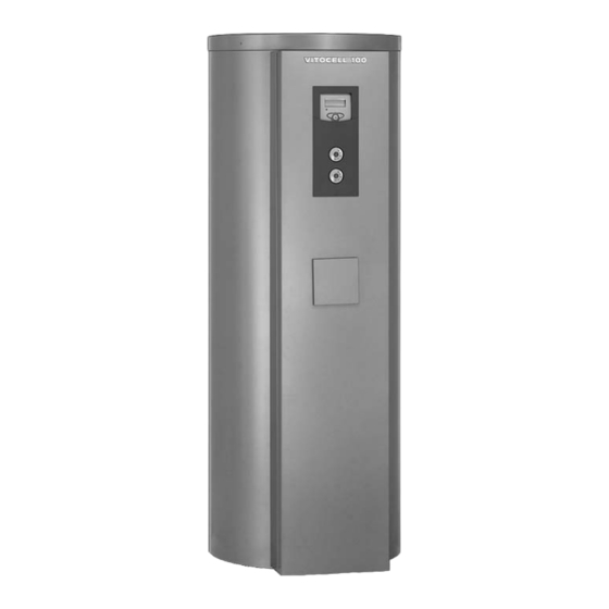
type cvu
dual-mode dhw cylinder with solar-set
vitocell 100-w
type cvu
dual-mode dhw cylinder with solar-set
Hide thumbs
Also See for VITOCELL 100-U:
- Installation instructions for contractors (24 pages) ,
- Service instructions manual (21 pages) ,
- Technical manual (144 pages)
Table of Contents
Advertisement
Quick Links
Download this manual
See also:
Technical Manual
Advertisement
Table of Contents

Related Manuals for Viessmann VITOCELL 100-U


Summary of Contents for Viessmann VITOCELL 100-U
-
Page 1: Installation Instructions
VIESMANN Installation instructions for contractors Vitocell 100-U Type CVU Dual-mode DHW cylinder with Solar-Set Vitocell 100-W Type CVU Dual-mode DHW cylinder with Solar-Set VITOCELL 100-U VITOCELL 100-W Dispose after installation. 5592 936 GB 8/2007... -
Page 2: Safety Instructions
Safety instructions Please follow these safety instructions closely to prevent accidents and material losses. Safety instructions explained & the Code of Practice of relevant trade associations, Please note & all current safety regulations as This symbol warns against the defined by DIN, EN, DVGW, TRGI, risk of material losses and TRF, VDE and all locally applicable environmental pollution. -
Page 3: Table Of Contents
Index Installation information Product information ..................& Vitocell 100-U and 100-W, type CVU ............& Connections .................... & Installation notes ..................Installation sequence Installing the Solar-Set................& Immersion heater ..................& Solar-Set fixings ..................& Fitting the Solar-Set ................. Hydraulic connection (on the solar side) ............ -
Page 4: Product Information
Product information Vitocell 100-U and 100-W, type CVU – Vitosolic 100 Enamelled DHW cylinder with internal – Pre-assembled pipework indirect coils for DHW heating in con- junction with solar heating systems, & Content: 300 litres freestanding and wall mounted boilers &... -
Page 5: Installation Notes
Product information (cont.) Installation notes Please note The thermal insulation must not be able to come into con- tact with naked flames. Exercise caution when welding and soldering. Please note & Allow an adequate distance to the To prevent material losses, wall to enable the thermostat (if install the DHW cylinder in a installed) to be operated. -
Page 6: Installing The Solar-Set
Installing the Solar-Set Immersion heater If an EHE immersion heater is & Route the supply cable of the EHE installed (accessory), we would immersion heater on the right side recommend to do this prior to fitting of the base support and secure with the base support for the Solar-Sets, the cable ties supplied. -
Page 7: Solar-Set Fixings
Installing the Solar-Set (cont.) Solar-Set fixings Insert the screws supplied approx. half way into the cylinder. -
Page 8: Fitting The Solar-Set
Installing the Solar-Set (cont.) Fitting the Solar-Set & Lead the base support for the Solar- & Tighten all 3 screws. Set with corresponding openings & Remove the cardboard transport through both screws and hook in. packing for securing the pump and &... -
Page 9: Lower Heating Water Connections (Solar)
Hydraulic connection (on the solar side) (cont.) Lower heating water connections (solar) Secure both pipelines (heating water return, solar A and heating water flow, solar B) with the flat packing- ings and union nuts supplied. Tighten the fixing clamps. A Heating water return of the solar heating system B Heating water flow of the solar heating system... -
Page 10: Upper Heating Water Connections (Solar)
Hydraulic connection (on the solar side) (cont.) Upper heating water connections (solar) A Heating water return of the solar B Heating water flow of the solar heating system heating system Note & Lead the upper 2 connection pipes (heating water return/flow, solar) Apply the thermal insulation of the through the appropriate 4 openings pipes after the installation over the... -
Page 11: Fitting The Safety Assembly
Fitting the safety assembly A Heating water return of the solar B Optional connection of the dia- heating system phragm expansion vessel (DEV) & Fit the safety assembly at the back of the DHW cylinder at the top to the heating water return, solar A. -
Page 12: Fitting The Thermometer Sensor And The Cylinder Temperature Sensor
Fitting the thermometer sensor and the cylinder temperature sensor Fitting the thermometer sensor Please note To prevent equipment damage, cables must not come into con- tact with hot parts. Ensure sufficient thermal insu- lation between the cables and hot pipework. -
Page 13: Fitting The Vitosolic 100 Cylinder Temperature Sensor At The Front
Fitting the thermometer sensor and the cylinder . . . (cont.) & Never wrap insulating tape around & Secure the thermometer sensor with the sensor. the short lead on the outside of the & Insert the thermometer sensor with contact spring of the sensor retainer the long lead into the clamping (not in the groove) so that it is flush bracket on the flange lid until it bot-... -
Page 14: Installing The Cylinder Temperature Sensor Of The Boiler Control Unit At The Back
Installing the cylinder temperature sensor of the boiler con- trol unit at the back Note The cylinder temperature sensor is supplied with the Viessmann boiler control unit or is available as an accessory. A Sensor well for cylinder tempera- ture control... -
Page 15: Connect Control Unit
Fitting the thermometer sensor and the cylinder . . . (cont.) & Never wrap insulating tape around the sensor. & Secure the cylinder temperature sensor on the outside of the contact spring of the sensor retainer (not in the groove) so that it is flush with the front of the spring. -
Page 16: Closing And Removing The Solar-Set
Closing and removing the Solar-Set Fitting the Solar-Set facia: & Hook in the Solar-Set facia with the 2 lower side tabs into the slots in the base support. & Push the facia in and push the 2 upper side locking bolts into the appropriate spring catches of the base support. -
Page 17: Checking The Anode Connection And Fitting The Lid
Checking the anode connection and fitting the lid A Magnesium anode C Thermometer lead B Earth lead D Type plate Note Guide the thermometer leads through the groove in the flange insulation. -
Page 18: Connections On The Heating Water And Solar Sides
Connections on the heating water and solar sides Permissible temperatures & Connect the pipework with detach- solar side 160 °C able fittings. heating water side 160 °C & Cap connections that are not Permissible operating required. pressure & Adjust the control thermostat so that solar side 10 bar the DHW temperature in the cylin-... - Page 19 DHW circulation Collector temperature sensor Heating circuit Cylinder temperature sensor Oil/gas fired boiler (solar side) Air separator Vitocell 100-U and 100-W, Stratification pump type CVU, comprising: Cylinder temperature sensor 2 DHW cylinder with Solar-Set (primary side) Solar set, comprising: 3 Fill valve...
-
Page 20: Connecting The Domestic Hot Water Side
Connections on the heating water and solar sides (cont.) 1. For heating water flow tempera- 4. Only for heating water flow tem- tures in excess of 95 ºC: peratures in excess of 110 ºC: Remove the cover bezels from the Install a type-tested high limit heating water side pipe outlets safety cut-out, if none has been... - Page 21 According to DIN 1988-2, a potable water filter should be installed in systems with metal pipework. Viessmann also recommends the installation of a drinking water filter when using plastic pipes according to DIN 1988 to prevent contaminants entering the DHW...
-
Page 22: Connecting The Earth Bonding
Connecting the domestic hot water side (cont.) Install the safety valve in the cold water pipe. It must not be able to be isolated from the DHW cylinder. The pipework between the safety valve and the DHW cylinder must not be restricted in any way. - Page 24 Viessmann Werke GmbH&Co KG Viessmann Limited D-35107 Allendorf Hortonwood 30, Telford Telephone: +49 6452 70-0 Shropshire, TF1 7YP, GB Fax: +49 6452 70-2780 Telephone: +44 1952 675000 www.viessmann.com Fax: +44 1952 675040 E-mail: info-uk@viessmann.com...
Need help?
Do you have a question about the VITOCELL 100-U and is the answer not in the manual?
Questions and answers