Table of Contents
Advertisement
Advertisement
Table of Contents

Related Manuals for Worcester Greenstar Comfort I RF


Summary of Contents for Worcester Greenstar Comfort I RF
- Page 1 Installation and operating instructions Radio Frequency Twin Channel Programmer/Receiver and Room Thermostat Greenstar Comfort I RF For EMS compatible Worcester Greenstar condensing boilers se le ct se le ct a d va n ce m e n u a d va n ce 6720810964-00.1Wo...
-
Page 2: Table Of Contents
Contents Contents Key to symbols and safety instructions ... 3 Servicing ........20 1.1 Key to symbols . -
Page 3: Key To Symbols And Safety Instructions
Key to symbols and safety instructions General safety instructions Key to symbols and safety instructions These installation instructions are intended for heating engineers, and electricians. Key to symbols ▶ Read any installation instructions (boiler, heating controls, etc.) carefully before starting the installation. Warnings ▶... -
Page 4: Comfort I Rf
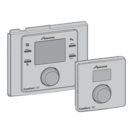
Comfort I RF Comfort I RF The Comfort I RF comprises a boiler or wall mounted twin channel Programmer/Receiver and wall mounted Room thermostat. Programmer/Receiver The boiler fascia mounted unit is a twin channel Programmer/Receiver and is connected to an RF Room thermostat transmitter. The Programmer/Receiver is for central heating and hot water control with modulating/enhanced load compensating boiler regulation. -
Page 5: Rf Room Thermostat
Comfort I RF RF Room thermostat The Room thermostat can only be used in conjunction with the Programmer/Receiver. The Room thermostat displays the current room temperature and is also used to set a new temperature set point. This information is transmitted back to the Programmer/Receiver to control the boiler output to maintain the desired room temperature. -
Page 6: Installation
Installation Programmer/boiler connection Installation NOTICE: EMS Connections ▶ The Programmer must NOT be CAUTION: Mains supplies connected to the boiler’s 230 volt ▶ Isolate the mains supplies to the boiler supply or an external 230 volt supply. before starting any work, and follow all relevant safety precautions ▶... -
Page 7: Time And Date Set Up
Installation The unit will initially display an error code A21 “No wireless signal to EMS interface”, refer to chapter 7 for information on fault codes. When they have established RF communications with each other, the Programmer/Receiver display will revert to a factory default time and date with the control in “Auto”... -
Page 8: Room Thermostat - Settings- Rf 1 Pair
Installation ▶ Turn the knob to select Radio settings ▶ To Pair the Room thermostat with the Programmer/ Receiver, turn the knob to select A ▶ Press the knob to display Pairing, that is RF pairing of the devices in the system ▶... - Page 9 Installation The thermostat must not be directly influenced by radiators or Wall mounting other appliances giving off heat, such as televisions or table Using the wall plate as a template, mark the position of the lamps. mounting screws. The mounting kit provided with the Room thermostat contains: ≥...
-
Page 10: Operation
Operation 1. Central heating operational status Operation 2. Current day 3. HW operational status The Programmer/Receiver is supplied with factory set default 4. Current time ON and OFF times, for central heating (CH) and hot water 5. Graphical indication of the current time program (HW), that are shown in the table below. -
Page 11: Programmer/Receiver Settings
Programmer/Receiver settings Programmer/Receiver settings There are two levels of settings: Time program 1. User Select Time program with the knob, and press to enter. Press the Return button at any time to return to the 2. Installer previous higher level. User In the Time program you can select ON and OFF times for the Press the menu button for more than three seconds to enter the... -
Page 12: Hot Water
Programmer/Receiver settings 5.1.2 Hot water To cancel the holiday function: This Time program is used to set your required ON and OFF ▶ Press the menu key for more than three seconds to enter times for the hot water. The Programmer has default time user menus and select Holiday, ON will be displayed. - Page 13 Programmer/Receiver settings ▶ Turn the knob to select ON or OFF, if ON is selected the 06:30 08:30 16:30 22:30 Programmer will automatically adjust the time in conjunction with daylight savings time ▶ Press the knob to confirm the selection ▶...
-
Page 14: Installer
The tenant should call this number to arrange a convenient date for the service. Landlords, call the Worcester Bosch technical support team for instructions of how to reset the Maintenance message or pmam contact telephone number. -
Page 15: Key Lock
Programmer/Receiver settings When the devices are being paired, the Room thermostat and Programmer/Receiver must be in the same mode of pairing. Refer to section 6.5 for pairing of the Room thermostat. Ensure that the Room thermostat is positioned as suggested in Section 3.2 and away from metal objects that might attenuate the RF signal. -
Page 16: Room Thermostat
Room thermostat Turn the knob anti-clockwise to decrease the temperature or Room thermostat clockwise to increase. The new temperature setting will flash for three seconds. After 30 seconds of inactivity the display reverts to the showing the current room temperature. Normal operation Under normal operation the display shows the current room temperature in centigrade. -
Page 17: Settings
Room thermostat Settings ▶ Turn the knob to select E 1 These functions are only used by the installer/service engineer and are useful during installation. To enter the Settings menu: If a fault code is displayed the user must first press the knob to return to the main display then the user can hold the knob to enter the Settings menu... -
Page 18: Rf 1 Pair With Other Devices
Room thermostat rF 1 Pair with other devices ▶ When the unit(s) have been unpaired or disconnected a zero will be displayed indicating that no units are The Programmer/Receiver and Room connected. thermostat are delivered together and are Press the knob, for more than three seconds, to return to the factory paired, they will automatically previous level, rF 1. -
Page 19: Troubleshooting
Troubleshooting Troubleshooting Temperature related faults Problem Cause Remedy The required room Airlock Bleed the radiators and vent the heating system. temperature has not been Low system pressure Top up the system pressure via the filling link achieved. Time program Is the heating on for long enough Flow temperature Set a higher flow temperature Thermostat valve in reference room... -
Page 20: Servicing
Servicing Servicing These units can not be serviced. Should either unit fail to function correctly check that the: ▶ Programmer/Receiver settings are correct ▶ RF signal link between the units is set up correctly, sections 6.5 and page 14 Radio settings ▶... -
Page 21: Erp Class
Your local waste management authority Package fiche and, subsequently, the ErP system data label. can supply details concerning the proper disposal of batteries. ERP Labelling obligation applicable from 26th September 2015. Supplier Worcester Bosch Group Model Comfort I ErP Class Function and Load compensation... - Page 22 Notes Comfort I – 6720810964 (2014/07)
- Page 23 Notes Comfort I– 6720810964 (2014/07)
- Page 24 0330 123 9119 TRAINING: 0330 123 0166 SALES: 0330 123 9669 Worcester, Bosch Group Cotswold Way, Warndon, Worcester WR4 9SW. Tel. 0330 123 9559 Worcester, Bosch Group is a brand name of Bosch Thermotechnology Ltd. worcester-bosch.co.uk *2703724_rev1* 6 720 810 964 (2014/07)
Need help?
Do you have a question about the Greenstar Comfort I RF and is the answer not in the manual?
Questions and answers