Table of Contents
Advertisement
Advertisement
Table of Contents

Related Manuals for Worcester Greenstar Comfort II RF


Summary of Contents for Worcester Greenstar Comfort II RF
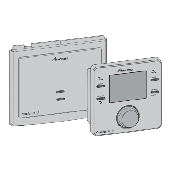
- Page 1 Installation and operating instructions Radio Frequency Twin Channel Programmable Room Thermostat and Receiver Greenstar Comfort II RF For EMS compatible Worcester Greenstar condensing boilers se le ct se le ct ad va nc e m en u ad va nc e 6720810965-00.1Wo...
-
Page 2: Table Of Contents
Contents Contents Key to symbols and safety instructions ... 3 Troubleshooting ......17 1.1 Key to symbols . -
Page 3: Key To Symbols And Safety Instructions
Key to symbols and safety instructions Key to symbols and safety instructions Key to symbols General safety instructions These installation instructions are intended for heating Warnings engineers, and electricians. ▶ Read any installation instructions (boiler, heating controls, Warnings in this document are identified by a etc.) carefully before starting the installation. -
Page 4: Comfort Ii Rf
Comfort II RF Comfort II RF The Comfort II RF comprises a wall mounted twin channel RF programmable room thermostat and a boiler or wall mounted RF receiver. Programmable room thermostat The wall mounted unit is a twin channel RF Programmable room thermostat. The Programmable room thermostat is for central heating and hot water control with modulating/enhanced load compensating boiler regulation. -
Page 5: Receiver
Comfort II RF installation Receiver ▶ Set time and date on the Programmable room thermostat ▶ The units will automatically connect to each other This unit is only used in conjunction with the Programmable room thermostat. ▶ Ensure that the signal strength is adequate at the The unit can be mounted in the boiler fascia, refer to your boiler Programmable room thermostat before mounting in a Installation, Commissioning and Servicing instruction manual... -
Page 6: Programmable Room Thermostat Mounting
Comfort II RF installation Optional wall mounting kit The Comfort II RF connects to your boiler’s EMS BUS connections only, on an edge connector identified either with B B or Using the wall plate as a template, mark the position of the mounting screws. -
Page 7: Date And Time Set Up
Comfort II RF installation Wall mounting plate To remove the wall mounting plate: 1. Insert a suitable flat bladed screwdriver into the slot on the bottom edge of the thermostat 2. Twist the screwdriver gently until the bottom catch is released. -
Page 8: Pairing/Unpairing The Units
Operation The Programmable room thermostat will display the current ▶ If Unpairing is chosen, press the knob and Unpairing is room temperature. displayed with advancing dashes, when the unpairing is completed a 0 is displayed confirming that the Set the current time and date Programmable room thermostat has been disconnected ▶... -
Page 9: Programmable Room Thermostat
Operation Programmable room thermostat 5. Burner ON - display when boiler is heating (can be up to 6 minutes delay) During normal operation the display shows: 6. Frost protection - displayed when boiler is set to OFF • the operational mode for the central heating, are either 7. -
Page 10: 4Setting A New Room Temperature
Programmable room thermostat settings that if the room temperature goes below 5 °C the boiler will 3. Holiday come on and maintain that temperature to prevent freezing. 4. Info 5. Settings pmam pmam Fig. 12 Permanently OFF 4.2.4 Setting a new room temperature Under normal operation the display shows the current room temperature. -
Page 11: 2Hw (Hot Water)
Programmable room thermostat settings ▶ The hours flash, turn the knob to select the hours setting If the Time settings 5 and 6 are not required, ▶ Press the knob to confirm at the end of Temp. setting 4 repeatedly press ▶... -
Page 12: 3Holiday Function
Programmable room thermostat settings ▶ Press the knob to confirm To cancel the holiday function: ▶ The minutes flash ▶ Press the menu key for more than three seconds to enter user menus and select Holiday, ON will be displayed. ▶... - Page 13 Programmable room thermostat settings Turn the knob to select Time/date and press to enter the – 24 hour function: ▶ Press the knob to confirm once the choice has been made ▶ When the desired format has been selected, turn the knob ▶...
-
Page 14: Installer
Programmable room thermostat settings options available. Turning the knob will select each option in 06:30 08:30 16:30 22:30 turn, eventually returning to the first option. 1. System data CH TEMP 20 °C 16 °C 21 °C 10 °C ▶ Turn the knob to select System data ▶... -
Page 15: Key Lock
Landlords: When the units have been paired, check the signal strength at ▶ Call the Worcester Bosch technical support the Programmable room thermostat. If the signal strength is team for instructions of how to set the low, try another position in that room until the best possible Maintenance message or contact signal strength is obtained, refer to page 12, section 5.1.4... -
Page 16: Receiver
Receiver Receiver The Receiver is paired with the Programmable room thermostat and they communicate via an RF signal. The Receiver unit has an Override/Pairing push button and a LED to indicate various sates of operation. Override push button If the RF signal between the Receiver and the Programmable room thermostat is lost the LED, on the Receiver, will flash once a second, indicating a local error (not a boiler fault). -
Page 17: Troubleshooting
Troubleshooting Troubleshooting Temperature related faults Problem Cause Remedy The required room Airlock Bleed the radiators and vent the heating system. temperature has not been Low system pressure Top up the system pressure via the filling link achieved. Time program Is the heating on for long enough Flow temperature Set a higher flow temperature Thermostat valve in reference room... -
Page 18: Servicing
Servicing Servicing These units can not be serviced. Should either unit fail to function correctly check that the: ▶ Programmable room thermostat settings are correct ▶ RF signal link between the units is set up correctly, sections 6.2 and page 15 Radio settings ▶... -
Page 19: Erp Class
(European ERP Labelling obligation applicable from 26th September Directive on waste electrical and 2015. electronic equipment). Supplier Worcester Bosch Group Use the country specific return and collection system for the disposal of Model Comfort II electrical and electronic equipment. - Page 20 0330 123 0166 SALES: 0330 123 9669 Worcester, Bosch Group Cotswold Way, Warndon, Worcester WR4 9SW. Tel. 0330 123 9559 Worcester, Bosch Group is a brand name of Bosch Thermotechnology Ltd. worcester-bosch.co.uk *2703726 REV1* Comfort II 6 720 810965 (2014/07)
Need help?
Do you have a question about the Greenstar Comfort II RF and is the answer not in the manual?
Questions and answers