
Related Manuals for Worcester Greenstar Sense I


Summary of Contents for Worcester Greenstar Sense I
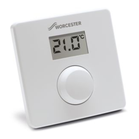
- Page 1 Installation and Operation Manual Operating unit Greenstar Sense I Intelligent Wired Room Thermostat 6 720 648 748-00.1O UK/IE...
-
Page 2: Table Of Contents
Contents Contents Key to symbols and safety instructions Explanation of symbols Safety regulations Product details Product data for energy consumption Technical specifications Function as room temperature-dependent controller Function as zone controller Function as an intelligent room thermostat Old electrical and electronic appliances Operation Information for installer Mounting... -
Page 3: Key To Symbols And Safety Instructions
Key to symbols and safety instructions Key to symbols and safety instructions Explanation of symbols Symbol Meaning ▶ Action step Cross-reference to other parts of this document or to other documents • List/list entry – List/list entry (second level) Flashing display (e.g. -
Page 4: Product Details
If an external cylinder primary pump is installed, the Sense I may only be used as a room thermostat. • Use in conjunction with Worcester FX controls FR10, FW100, FR110 is not possible. • Some settings may not be available, depending on the connected heat source. -
Page 5: Product Data For Energy Consumption
Product details Product data for energy consumption The specified product data correspond to the requirements of the EU Regulation No. 811/2013 which supplements ErP Directive 2010/30/EU. The class of the temperature controller is required to calculate the room heating energy efficiency of an integrated system and is for this reason incorporated into the system data sheet. -
Page 6: Technical Specifications
Product details Technical specifications Technical data Measurements (W × H × D) 82 × 82 × 23 mm Rated voltage 10 – 24 V DC Rated current 4 mA BUS interface EMS/EMS 2 (2-wire BUS) Control range 5 – 30 °C Permiss. -
Page 7: Function As An Intelligent Room Thermostat
Old electrical and electronic appliances control of the zones a Sense II can be used instead of a Sense I (combination of 1 Sense II and a maximum of 2 Sense I with a wiring module). The control of the zone temperature is thus achieved in the same way as in the case of the function as room temperature-dependent controller with adjusted flow temperature control. -
Page 8: Operation
Operation Operation °C °F 6 720 648 748-01.1O Fig. 1 Overview of control elements 1 Display 2 Control knob • Turn: choose and change settings. • Press: confirm entry or switch display. Description of the displays Example Current room temperature (standard display) °C °F Required room temperature:... -
Page 9: Information For Installer
Information for installer Setting the required room temperature Result ▶ Turn the control knob to set the required room temperature. °C °F ▶ Press the control knob to apply the setting. °C °F Switch off the heating system Result ▶ Turn the control knob anti-clockwise to reduce the required °C room temperature until OFF shows on the display. - Page 10 Information for installer 6 720 648 748-02.1O Fig. 3 Removing Sense I from wall base 6 mm 6 mm 3.5 mm 3.5 mm 6 720 648 748-04.1O Fig. 4 Installing wall base Electrical connection Power is supplied to the user interface via the BUS cable. The polarity of the wires is irrelevant.
- Page 11 Information for installer ▶ Use a cable of at least type H05 VV-... (NYM-J...). ▶ In the case of external inductive interferences (e.g. from PV systems), use shielded cables (e.g. LIYCY) and earth the shield on one side. Connect the shield to the building's earthing system, e.g.
-
Page 12: Commissioning
Information for installer Commissioning The following tables illustrate Sense I commissioning requirements on installation or first start-up following a reset. Zone controller with wiring module (systems with several heating circuits without higher-level control) ▶ Switch system ON/reset Sense I. °C The Display shows 3 dashes, until the connection to the boiler is °F established and Sense I asks for heating circuit selection (HC1... -
Page 13: Settings In The Service Menu
Information for installer Settings in the service menu Overview of settings Adjustment Adjustments range Description CO | Fb | SC Controller (CO), room thermostat (Fb), zone controller (SC) HC1 | HC2 | Heating circuit 1 to 4 HC3 | HC4 2 | 3 | 4 Control characteristics: •... - Page 14 Information for installer Reset or power failure In the event of a reset (with F.1 = 1), the Sense I goes back to its standard settings, i. e. it appears after this as a zone controller with all its factory settings. On restarting after a power failure, the Sense I appears as the previously configured control, i.
-
Page 15: Troubleshooting
Troubleshooting Closing the service menu Result ▶ Press and hold control knob until three dashes appear. °C °F ▶ Release control knob. °C The display changes to the standard display, and the °F programming unit works with the changed settings. Troubleshooting ▶... -
Page 16: Display Of A Current Fault
Troubleshooting Display of a current fault If a fault occurs the display shows the respective fault code and the 3 digit sub code. In case of 4 digit sub codes, after displaying the fault code the display shows the first 2 digits and then the last 2 digits of the sub code (e. - Page 17 Troubleshooting Possible causes and assistance from the contractor 3091 Room temperature sensor of the Sense I defective (A61/ 3091: heating circuit 1, ..., A64/3094: heating circuit 4). 3094 ▶ Replace faulty Sense I. Fill The operating pressure of the heating system is too low. ▶...
- Page 18 Notes 6 720 648 748 (2014/03)
- Page 19 6 720 648 748 (2014/03)
- Page 20 0330 123 9119 TRAINING: 0330 123 0166 SALES: 0330 123 9669 Worcester, Bosch Group Cotswold Way, Warndon, Worcester WR4 9SW. Tel. 0330 123 9559 Worcester, Bosch Group is a brand name of Bosch Thermotechnology Ltd. worcester-bosch.co.uk 6 720 648 748...
Need help?
Do you have a question about the Greenstar Sense I and is the answer not in the manual?
Questions and answers