Worcester MT10RF Instruction Manual
Mechanical/rf thermostat
Hide thumbs
Also See for MT10RF:
- Installation and operating instructions manual (20 pages) ,
- Instruction manual (12 pages)
Advertisement
Table of Contents
Advertisement
Table of Contents

Related Manuals for Worcester MT10RF


Summary of Contents for Worcester MT10RF
- Page 1 MT10RF/MECHANICAL RF THERMOSTAT Radio frequency controlled single channel mechanical timer and room thermostat with receiver 7-716-192-037 FOR GREENSTAR i, GREENSTAR Si and GREENSTAR CDi MODELS override override INSTRUCTION MANUAL FITTING & OPERATING INSTRUCTIONS...
- Page 2 the nation’s favourite PLUMBING & HEATING SUPPLIES FREE SHIPPING SECURE PAYMENTS on all orders over £100 to mainland UK shop online with confidence FINANCE AVAILABLE PRICE MATCH spread the cost with low interest rates always get the best deals available we have H U G E R E D U C T I O N S...
- Page 3 CAREFULLY BEFORE STARTING. TECHNICAL: 08705 266241 SERVICE: 08457 256206 THESE INSTRUCTIONS ARE APPLICABLE TO THE WORCESTER PRODUCT MODEL(S) STATED ON SPARES: 01905 752571 THE FRONT COVER OF THIS MANUAL ONLY AND LITERATURE: 01905 752556 MUST NOT BE USED WITH ANY OTHER MAKE...
-
Page 4: Table Of Contents
CONTENTS ACCESSORY INFORMATION GENERAL INFORMATION TECHNICAL DATA INSTALLATION & COMMISSIONING FITTING THE RECEIVER TRANSMITTER RADIO LINK SETUP & LOCATION TRANSMITTER CLEARANCES & FIXING USER INSTRUCTIONS TRANSMITTER CONTROLS RECEIVER FUNCTIONS BATTERY REPLACEMENT SERVICING & SPARES TRANSMITTER/RECEIVER MAINTENANCE & SPARES FITTING & OPERATING INSTRUCTIONS CONTENTS 8-716-107-486d (12.06) -
Page 5: General Information
GENERAL INFORMATION STANDARD PACKAGE: A - Receiver for the Greenstar i, Greenstar Si and Greenstar CDi models. B - Transmitter. C - Screws (x2). D - Wall Plugs (x2). E - Instructions. F - Batteries (x2). SPECIFICATIONS: Transmitter: • Single channel, radio frequency central heating timer. -
Page 6: Technical Data
TECHNICAL DATA DESCRIPTION UNITS TRANSMITTER RECEIVER Dimensions H158xW75xD36.5 Operating voltage 2xLR6/AA batteries 24v DC Ambient operating temperature °C -5 to +45 -5 to +45 Class of protection Degree of protection Accuracy sec/day ±2.5 @ 25°C Battery life year 1 approx. Shortest switching period minutes Temperature regulation range... -
Page 7: Fitting The Receiver
FITTING THE RECEIVER DANGER - 24V & 230V: DO NOT TOUCH THE ELECTRICAL COMPONENTS OR CIRCUITS. CAUTION: ISOLATE THE MAINS ELECTRICITY SUPPLY BEFORE STARTING ANY WORK AND OBSERVE ALL RELEVANT SAFETY PRECAUTIONS. OBSERVE ELECTRONIC STATIC DISCHARGE PRECAUTIONS. DO NOT TOUCH THE PCB CIRCUITS Important: Switch off boiler. -
Page 8: Transmitter Radio Link Setup & Location
TRANSMITTER RADIO LINK SETUP & LOCATION Radio Link setup: First remove the transmitter baseplate: Locate a flat bladed screwdriver into the slots in the baseplate (B), as shown and twist to lift the transmitter top (A) away from the baseplate (B). Establishing a radio link: Press and hold button (C) down on the receiver for approximately 5... -
Page 9: Transmitter Clearances & Fixing
TRANSMITTER CLEARANCES & FIXING TRANSMITTER CLEARANCES: See diagram opposite for minimum area (shown in mm) required for operation. SAFETY: All relevant safety precautions must be undertaken. Protective clothing, footwear, gloves and safety goggles must be worn as appropriate. TRANSMITTER FIXING: Hold baseplate (B) level to mark securing points (C) and remove baseplate (B). -
Page 10: Transmitter Controls
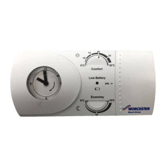
TRANSMITTER CONTROLS INFORMATION: Slide open panel (A) to expose quick reference user instructions (B). SETTING THE 24 HOUR CLOCK: Slide cover (D) off the transmitter (C). Rotate outer ring (E) in direction of arrow (clockwise) until the clock hands and the 24 hour pointer (F) display the correct time. -
Page 11: Receiver Functions
RECEIVER FUNCTIONS 1 NORMAL OPERATION: LED (A) is continuously on when there is a demand for heating and continuously off when there is no demand for heating. override Note: The LED is briefly interrupted each time a signal is received. override 2 SIGNAL RECEIVED: LED (A) flashes twice each time a... -
Page 12: Battery Replacement
BATTERY REPLACEMENT TO REPLACE THE BATTERIES: Do not use rechargeable batteries. Locate flat bladed screwdriver into slots and twist to lift top of transmitter (A) away from baseplate (B). Remove existing batteries (C) and dispose of safely, do not touch the circuits inside the transmitter. -
Page 13: Transmitter/Receiver Maintenance & Spares
TRANSMITTER/RECEIVER MAINTENANCE & SPARES Transmitter maintenance: Wipe outer casing (A) with a clean dry cloth, do not use polish or detergents. Do not touch any circuits inside the transmitter. Receiver maintenance: The receiver unit (B) requires no maintenance and has no serviceable components.
Need help?
Do you have a question about the MT10RF and is the answer not in the manual?
Questions and answers