Kohler 8RESV Operation
Residential/commercial generator sets
Hide thumbs
Also See for 8RESV:
- Installation manual (48 pages) ,
- Installation instructions (2 pages) ,
- Service manual (140 pages)
Table of Contents
Advertisement
Quick Links
See also:
Installation Manual
Advertisement
Table of Contents
Troubleshooting

Related Manuals for Kohler 8RESV


Summary of Contents for Kohler 8RESV
- Page 1 Operation Residential/Commercial Generator Sets Models: 8/10/12RESV 8/10/12RESVL Controllers: RDC2 TP-6880 10/14a...
-
Page 2: Product Identification Information
California Proposition 65 WARNING Engine exhaust from this product contains chemicals known to the State of California to cause cancer, birth defects, or other reproductive harm. Product Identification Information Controller Identification Product identification numbers determine service parts. Record the product identification numbers in the spaces Record the controller description from the generator set below immediately after unpacking the products so that operation manual, spec sheet, or sales invoice. -
Page 3: Table Of Contents
Table of Contents Safety Precautions and Instructions ............Introduction . - Page 4 ........... . 5.4.1 Air Cleaner, 8RESV/RESVL Models ......
-
Page 5: Safety Precautions And Instructions
Safety Precautions and Instructions Accidental Starting IMPORTANT SAFETY INSTRUCTIONS. WARNING Electromechanical equipment, including generator sets, transfer WARNING switches, switchgear, and accessories, can cause bodily harm and pose life-threatening danger when improperly installed, operated, maintained. To prevent accidents be Explosion. Can cause severe injury or death. aware of potential dangers and act safely. - Page 6 Battery gases. Explosion can cause Servicing the air cleaner. A sudden Generator set operation. Carbon severe injury or death. Battery gases backfire can cause severe injury or monoxide can cause severe nausea, can cause an explosion. Do not smoke death. Do not operate the generator fainting, or death.
- Page 7 Fuel System Hazardous Noise WARNING CAUTION WARNING Hazardous voltage. Backfeed to the utility system can cause property damage, severe Hazardous noise. injury, or death. Explosive fuel vapors. Can cause hearing loss. Can cause severe injury or death. If the generator set is used for Never operate the generator set standby power, install an automatic Use extreme care when handling,...
-
Page 8: Hot Parts
Hot Parts Notice Welding on the generator set. Can cause severe electrical equipment damage. Before welding on the NOTICE WARNING generator set perform the following Canadian installations only. steps: (1) Remove the battery cables, standby service connect the output of negative (--) lead first. -
Page 9: Introduction
Operation/Installation Manual, Model Information in this publication represents data available RDT Automatic Transfer Switch TP-6345 at the time of print. Kohler Co. reserves the right to Installation Manual, Model RSB change this publication and the products represented Automatic Transfer Switch... - Page 10 The following illustration shows a typical generator set The exhaust emission control system for the SV620 nameplate. Copy the model, serial, and specification engines (8RESV/RESVL) is EM for U.S. EPA, numbers from the nameplate into the spaces provided in California, and Europe.
-
Page 11: Service Assistance
Visit the Kohler Power Systems website at Phone: (86) 21 6288 0500 KOHLERPower.com. Fax: (86) 21 6288 0550 Look at the labels and stickers on your Kohler product India, Bangladesh, Sri Lanka or review the appropriate literature or documents India Regional Office included with the product. - Page 12 Notes Service Assistance TP-6880 10/14...
-
Page 13: Section 1 Descriptions And Service Views
1.2 Engine 1.5 Transfer Switch The 8RESV generator set has a four-cycle, single The RDC2 and DC2 controllers are designed to cylinder, air-cooled Kohlerr engine and 10/12RESV interface with and control the Kohler Model RXT generator sets have a four-cycle, twin cylinder, Automatic Transfer Switch (ATS). - Page 14 Test function diagnostics Unloaded full-speed exercise Loaded full-speed exercise (Model RXT ATS required) Front-access mini USB connector for SiteTecht connection or the Kohler USB utility Integral Ethernet connector for Kohlerr OnCuer Plus Section 1 Descriptions and Service Views TP-6880 10/14...
-
Page 15: Oncue Plus Generator Management System
Engine runtime hours Maintenance reminders A laptop computer and Kohlerr SiteTech software or Kohler USB Utility software can be used to update OnCuer Plus status (connected/disconnected) controller firmware Date and time displays See the generator set Installation manual for more Smart engine cooldown senses engine temperature information. -
Page 16: Accessories
1.8 Accessories 1.8.4 Load Shed Kit The optional Load Shed Kit functions in a similar fashion The following optional accessories are offered for the as the Load Control Module (LCM) and provides an RESV and RESVL generator sets. automatic load management system to comply with Section 702.5 of NEC 2008. -
Page 17: Service Views
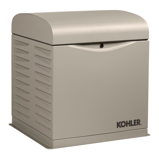
1.9 Service Views ADV-8539 1. Hinged roof 10. Line circuit breaker 2. Air cleaner 11. 120 VAC receptacles for optional carburetor heater (not shown) 3. Nameplate location 12. Lock 4. Thermostat 13. Locking tool, provided with generator set 5. Engine starting battery location (battery purchased separately) 14. - Page 18 20. Lifting holes 22. Exhaust outlet 21. Air intake Figure 1-3 Service View Section 1 Descriptions and Service Views TP-6880 10/14...
-
Page 19: Section 2 Generator Set Operation
Section 2 Generator Set Operation 2.1 Prestart Checklist WARNING WARNING Sulfuric acid in batteries. Can cause severe injury or death. Accidental starting. Can cause severe injury or death. Wear protective goggles clothing. Battery acid may cause Disconnect the battery cables before blindness and burn skin. - Page 20 Grounding electrical equipment. Hazardous voltage can WARNING cause severe injury or death. Electrocution is possible whenever electricity is present. Ensure you comply with all applicable codes and standards. Electrically ground the generator set, transfer switch, and related equipment and electrical circuits. Turn off the main circuit breakers of all power sources before servicing the equipment.
-
Page 21: Exercising The Generator Set
2.2 Exercising the Generator Set 2.3.5 Engine Cooldown The engine cooldown time delay allows the engine to Operate the generator set without load once each week run after the loads have been removed. for 20 minutes. See Section 2.4 for information about loaded and unloaded exercise modes. -
Page 22: Automatic Operation With Other Transfer Switches
If a transfer switch other than the Model RXT (such as a The DC2 controller does not prompt you to set the Kohler Model RDT or RSB) is used, the engine start exerciser. See Section 4.5 for instructions to set the contacts from the ATS must be connected to engine exerciser on the DC2. -
Page 23: Unloaded Full-Speed Exercise
2.4.3 Unloaded Full-Speed Exercise System Diagnostics During the unloaded exercise, the controller monitors The unloaded full-speed exercise runs the generator set the following data. The controller display indicates that at full speed for 20 minutes without transferring the load. the generator set is running, unless a fault is detected as described below. -
Page 24: Faults
2.5 Faults 2.5.4 Resetting the Controller after a Fault Shutdown The RDC2/DC2 controller displays fault messages for generator set warnings and shutdowns. Selected fault Always identify and correct the cause of a fault messages are shown in Figure 2-3. shutdown before resetting the controller. Check the fault message displayed on the controller and refer to Figure 2-3 to identify and correct the fault condition 2.5.1... -
Page 25: Fault Messages
Warning (W) or Shutdown (SD) Condition Fault Message Check AC Sens Loss W (1 sec.) AC sensing lost. In Auto mode, generator output Contact an authorized AC sensing is lost. Detection begins 10 seconds distributor/dealer for service. SD (3 sec.) * after crank disconnect. - Page 26 Warning (W) or Shutdown (SD) Condition Fault Check Frequency High SD * Governed frequency exceeds 110% of the Contact an authorized system’s frequency setpoint for more than 10 distributor/dealer for service. seconds. Function becomes active 10 seconds after engine start (10 second inhibit). Frequency Low SD * Governed frequency falls below 90% of the...
-
Page 27: Generator Enclosure Thermostat
2.6 Generator Enclosure Thermostat 8RESV(L), 10RESV(L), and 12RESV(L) generators include a resettable thermostat in the air intake compartment. The thermostat detects excess heat inside the enclosure. If the thermostat trips, the generator will shut down and the controller will display a fault (underspeed, underfrequency, or undervoltage). - Page 28 Notes Section 2 Generator Set Operation TP-6880 10/14...
-
Page 29: Section 3 Rdc2 Controller Operation
DC2 controller. See Section 4 for DC2 controller operation information. The RDC2 controls the following power system components: Model 8RESV, 10RESV, or 12RESV generator set Model RXT Automatic Transfer Switch (ATS) Load Control Module (LCM) or load shed kit GM77569 Programmable Interface Module (PIM) 1. -
Page 30: Controller Keypad
3.2.1 Controller Keypad 3.2.2 LED Indicators The RUN, OFF, and AUTO buttons control the generator LEDs above the RUN, OFF, and AUTO buttons indicate set as described in Figure 3-3. the mode of operation as shown in Figure 3-4. Use the Select, Up arrow, and Down arrow buttons to Power System LEDs indicate the status of the utility navigate through the menus and change settings, if power and the generator set, and indicate which source... -
Page 31: Lcd Display
3.2.3 LCD Display The display contrast is adjustable. Navigate to the Genset System menu and step down to the Contrast The controller is equipped with a two-line x 16 character screen. Press the Select button, and then use the up and backlit digital display with adjustable contrast. -
Page 32: Controller Power
Note: If no buttons are pushed, the controller exits the menus and returns to the generator set status Have controller setup and adjustment performed only by display after 5 minutes. an authorized Kohler distributor/dealer or authorized representative. Section 3 RDC2 Controller Operation TP-6880 10/14... - Page 33 Changing Settings on the RDC2 Controller 1. Press the Select button to enter the main menu. 8. When the correct date is shown, press the Select button. The saved date is shown. Overview ----> Press: Display: Date: 1.2 h Press: Display: 03Jan2012 2.
-
Page 34: Setting The Exerciser
3.6 Setting the Exerciser 7. Press the Select button. The setting flashes to show that it can be changed. For example, HR Set the exerciser to automatically run the generator set flashes to show that the hour can be changed. for 20 minutes every week or every two weeks. - Page 35 Genset ----> System Freq: System XX.X Hz System Phase System Volt Battery V: HOLD: Next Exercise * Next Exercise HR:MN PM MM/DD/YY HR:MN PM MM/DD/YY HOLD: Exercise Mode: Exercise Mode: Unloaded Cycle/Unloaded Loaded Full/ Loaded Full HOLD: Exercise Freq: Exercise Freq: Weekly Weekly/Bi-Weekly Language:...
-
Page 36: Rdc2 Controller Menus
3.7 RDC2 Controller Menus If a setting on the controller display is flashing, edit mode has been enabled. Press the OFF or AUTO button to exit Controller menus display power system information, the edit mode. including status information for the engine, generator, and optional RBUS accessories, exercise settings, and 3.8 Main Menu event history. -
Page 37: Overview Menu
3.9 Overview Menu 3.10 Engine Metering Menu The engine metering menu displays engine status information as shown in Figure 3-11. This menu displays status information only. No settings can be Overview ----> Active Alert changed from this menu. 1.2 h (if any) Eng Speed: Engine ---->... -
Page 38: Generator Metering Menu
The voltage calibration mode can be entered from the Generator Metering menu. Contact a Kohler-authorized distributor/dealer for service. The Reset Calibration menu allows you to set the voltage reading back to the original value after calibration, if necessary. See Figure 3-12. -
Page 39: Generator Set Information Menu
A personal computer The Next Maintenance menu shows the number of running Kohler SiteTech software is required to enter the hours of generator set operation until maintenance is generator set model number and serial numbers on a required. -
Page 40: Genset System Menu
240 V System factory set and should not require changes to the system settings in the field. A Kohler authorized distributor or dealer can adjust System Freq: these settings, if necessary. If the generator set is 60 Hz reconnected to a different voltage or the system settings require adjustment for some other reason, see Section 3.5 for instructions to enable editing and change the... -
Page 41: Ats Status Menu
3.15 ATS Status Menu The ATS Status menu displays Model RXT transfer switch and source information. ATS menus appear if a Model RXT transfer switch is The voltage shown in these menus can be calibrated. connected to the generator set. If no transfer switch is Follow the safety precautions at the beginning of this connected, or another model ATS is connected to the manuals. -
Page 42: Ats Configuration Menu
3.16 ATS Configuration Menu Note: The ATS Configuration menu appears only if a ATS ----> Normal Freq: Model RXT transfer switch is connected. Configuration 12.3 Hz Use the ATS Configuration submenu to check the Model RXT transfer switch system settings and time delays, and change the settings, if necessary. -
Page 43: Date And Time Menu
3.17 Date and Time Menu Date and The date and time will typically be set at controller Date: Time power--up. To change the date, time, or time format 02Dec2011 (12 hour or 24 hour), use the Date and Time menu. See Figure 3-18. -
Page 44: Networking Status Submenu
3.18.1 Networking Status Submenu If DHCP is enabled, IP parameters are not displayed. If DHCP is disabled (i.e., if a static IP address is used), the The Networking Status submenu contains settings for IP parameters are displayed. OnCuer Plus. See the OnCue Plus Software Operation Manual for information about the appropriate network To enable or disable DHCP and change the IP settings, settings for OnCue Plus. -
Page 45: Networking Configuration Submenu (Oncue Plus Password)
3.18.2 Networking Configuration reset after the OnCue Plus system has been set up, the connection will be lost. Disconnect the battery power to Submenu (OnCue Plus Password) the controller, wait a minute, then reconnect power. The Networking Configuration menu includes settings used for communication with the Kohlerr OnCuer Plus DHCP Submenu Generator Management System. - Page 46 Networking----> Networking----> Status Information HOLD Networking Reset OnCue Reset OnCue Configuration Password? No Password UP arrow for YES, Down arrow for NO. RBUS ----> Reset OnCue Information Password? Yes Press Select to enter YES or NO as displayed. New password is displayed for approximately 10 seconds.
-
Page 47: Rbus Information
3.18.3 RBUS Information Model RXT transfer switch The RBUS Information menu contains settings for Programmable Interface Module (PIM) remote modules that communicate with the RDC2 Load Control Module (LCM) or load shed kit controller using RBUS protocol. This includes the following optional modules: Networking---->... -
Page 48: Remote Devices Submenu
3.18.4 Remote Devices Submenu The serial numbers for the PIM and LCM or load shed kit are printed on the circuit boards inside the enclosures. Check the status of remote devices communicating through RBUS. Device types can include: Model RXT ATS Programmable Interface Module (PIM) Load Control Module (LCM) or load shed kit From Figure 3-22:... -
Page 49: Programmable Interface Module (Pim) Status Menu
3.19 Programmable Interface A personal computer running Kohlerr SiteTecht software is required to change the input and output Module (PIM) Status Menu settings. Contact an authorized distributor or dealer for service. The PIM status menu displays the status of inputs and outputs connected to the programmable interface The Kohlerr OnCuer Plus Management System can be module (PIM). -
Page 50: Load Control Module (Lcm) Or Load Shed Kit Menus
3.20 Load Control Module (LCM) or or load shed kit adds and sheds loads based on the generator current. Load Shed Kit Menus The test function cycles the relays in the order of their The Load Control menu displays the status of the Load priority. -
Page 51: Event Log
3.21 Event Log To stop viewing the event history before the last event, press the select button to return to the main menu. The event log displays up to 1000 controller faults and notices, starting with the most recent event. Events are numbered 1--1000, with 1 being the most recent. - Page 52 Notes Section 3 RDC2 Controller Operation TP-6880 10/14...
-
Page 53: Section 4 Dc2 Controller Operation
Section 4 DC2 Controller Operation 4.1 DC2 Generator Set/ Transfer Switch Controller Model RESVL generator sets are equipped with the DC2 generator set/transfer switch controller. Model RESV generator sets are equipped with the RDC2 generator set/transfer switch controller. See Section 3 for RDC2 controller operation information. The DC2 controls the following power system components: Model 8RESVL, 10RESVL, or 12RESVL generator... -
Page 54: Controller Keypad
4.2.1 Controller Keypad 4.2.2 LED Indicators The RUN, OFF, and AUTO buttons control the generator LEDs above the RUN, OFF, and AUTO buttons indicate set as described in Figure 4-3. the mode of operation as shown in Figure 4-4. Use the EXERCISE button to set the exerciser on the DC2 controller. -
Page 55: Lcd Display
4.2.3 LCD Display Active Alert The controller is equipped with a two-line x 16 character (if any) backlit digital display with adjustable contrast. When the generator set is running, the messages shown in Figure 4-5 are displayed. When the system is in AUTO, Genset State the LCD display steps through the status messages Standby... -
Page 56: Exercise
4.5 Exercise 4.5.3 Exerciser Reset To reset the exerciser to run at a different day and/or The DC2 controller can be set to automatically run the time, follow the procedure in Section 4.5.2 to enter the generator set at the same time and day each week. new exerciser settings. -
Page 57: Maintenance Timer
4.7 Maintenance Timer 4.8 OnCue Plus Password The maintenance timer keeps track of the time until the To set the OnCuer Plus password on the DC2 controller, next recommended maintenance according to the 1. Press the OFF button and verify that the generator maintenance schedule for the generator set. - Page 58 Notes Section 4 DC2 Controller Operation TP-6880 10/14...
-
Page 59: Section 5 Scheduled Maintenance
Section 5 Scheduled Maintenance DANGER WARNING Hazardous voltage. Accidental starting. Will cause severe injury or death. Can cause severe injury or death. This equipment must be installed and Disconnect the battery cables before serviced qualified electrical working generator set. personnel. Remove the negative (--) lead first when disconnecting the battery. -
Page 60: Scheduled Maintenance
The fuel system. Explosive fuel vapors can cause severe Routine Maintenance. Refer to the following generator injury or death. Vaporized fuels are highly explosive. Use set service schedule, the engine service schedule, and extreme care when handling and storing fuels. Store fuels in a the runtime hours displayed on the generator set well-ventilated area away from spark-producing equipment controller to determine when to schedule routine... -
Page 61: Service Schedule
Air cleaner service [ Yearly or hours shown Spark plugs (apply anti-seize lubricant for easy Yearly or 500 hours removal) Have valve lash checked/adjusted, 8RESV(L) Engine SM 100 hours Have valve lash checked/adjusted, 10/12RESV(L) Engine SM 500 hours Replace stepper motor coupling and bushing... -
Page 62: Lubrication System
5.2 Lubrication System 5.2.3 Engine Oil Recommendation Use 5W-30 API (American Petroleum Institute) Service See the service schedules in Section 5.1 for oil change Class SG, SH, or SJ synthetic oil. Synthetic oil oxidizes and oil filter replacement intervals. See the service and thickens less than other oils and leaves the engine views in Section 1.9 for the oil drain, oil check, oil fill, and intake valves and pistons cleaner. - Page 63 Disconnect the utility power to the generator Generator Set Model Oil Capacity, L (qt.) set. 8RESV/RESVL 1.5 (1.6) c. Disconnect the generator set engine starting 10/12RESV/RESVL 1.9 (2.0) battery, negative (--) lead first.
-
Page 64: Resetting The Maintenance Timer
5.2.5 Resetting the Maintenance Timer 2. Remove the spark plug and check its condition. Replace the spark plug if it is worn or if its reuse is questionable. Model RESV (RDC2): 3. Check the spark plug gap using a wire feeler 1. -
Page 65: Air Cleaner Service
7. Check the air cleaner base. Make sure it is secure and not bent or damaged. Also check the element 5.4.1 Air Cleaner, 8RESV/RESVL cover for damage and fit. Replace all damaged air Models cleaner components. Remove any loose dirt or debris from the air cleaner base. -
Page 66: Air Cleaner, 10/12Resv/Resvl Models
9. Position the air cleaner cover with levers outward over air cleaner; turn levers inward to lock. tp6515 10. When element replacement is necessary, order genuine Kohler parts. 1. Air cleaner cover lever 4. Blower housing 2. Air cleaner element 5. -
Page 67: Exhaust System
5.6 Exhaust System CAUTION WARNING Hazardous noise. Can cause hearing loss. Carbon monoxide. cause severe nausea, Never operate the generator set fainting, or death. without a muffler or with a faulty exhaust system. exhaust system must leakproof and routinely inspected. WARNING Generator set operation. -
Page 68: Battery
5.7 Battery Battery short circuits. Explosion can cause severe injury or death. Short circuits can cause bodily injury and/or equipment damage. Disconnect the battery before generator set installation or maintenance. Remove all jewelry before WARNING servicing the equipment. Use tools with insulated handles. Remove the negative (--) lead first when disconnecting the battery. -
Page 69: Storage Procedure
5.8 Storage Procedure 5.8.3 Cylinder Lubrication 1. Remove the spark plugs. Perform the following storage procedure before removing the generator set from service for three 2. Pour one tablespoon of engine oil into each spark months or longer. Follow the engine manufacturer’s plug hole. - Page 70 Notes Section 5 Scheduled Maintenance TP-6880 10/14...
-
Page 71: Section 6 Troubleshooting
If the generator set circuit breaker trips repeatedly, actions. contact an authorized Kohler distributor/ dealer for service. If the procedures in this manual do not explain how to correct the problem, contact an authorized Kohler 6.4.1... -
Page 72: Troubleshooting
Line circuit breaker tripping because of Reduce the load on the generator set. overload. Line circuit breaker tripping because of short Contact an authorized Kohler distributor/dealer for circuit. service. Auxiliary winding circuit breaker tripped. Reset the circuit breaker (located in junction box). -
Page 73: Appendix A Abbreviations
(2 bytes) est. estimated Canadian Electrical Code KBus Kohler communication protocol E-Stop emergency stop cert. certificate, certification, certified kilogram etc. et cetera (and so forth) cubic feet per hour TP-6880 10/14 Appendix 73... - Page 74 kg/cm kilograms per square normally closed remote terminal unit centimeter National Electrical Code room temperature vulcanization kilogram-meter NEMA National Electrical read/write kg/m kilograms per cubic meter Manufacturers Association Society of Automotive kilohertz NFPA National Fire Protection Engineers Association kilojoule scfm standard cubic feet per minute newton meter kilometer...
- Page 76 7 Jurong Pier Road Singapore 619159 Phone (65) 6264-6422, Fax (65) 6264-6455 For the nearest KOHLER authorized installation, service, and sales dealer in the US and Canada: TP-6880 10/14 Call 1-800-544-2444 or visit KOHLERPower.com E 2014 by Kohler Co. All rights reserved.
Need help?
Do you have a question about the 8RESV and is the answer not in the manual?
Questions and answers