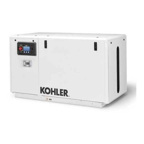
Kohler 4EOZ Installation Instructions Manual

Kohler 4EOZ Installation Instructions Manual

Marine generator sets
Hide thumbs Also See for 4EOZ:

Advertisement

6.5EFOZ/8EOZ, 8.5EFOZ, 9EFOZ/10EOZ
11EFOZ/13EOZ, 11.5EFOZ/14EOZ
13EFOZ/15.5EOZ, 16EFOZ/20EOZ
17.5EFOZ/20EOZ, 19EFOZ/23EOZ
20EFOZ/24EOZ, 23EFOZ/28EOZ
27EFOZ/32EOZ, 33EFOZ/40EOZ
40EFOZ/50EOZ, 55EFOZ/65EOZ
70EFOZ/80EOZ, 80EFOZ/99EOZ
100EFOZ/125EOZ, 125EFOZ/150EOZ
3.5EFOZ/4EOZ, 4EFOZ/5EOZ
Installation
Marine Generator Sets
Models:
TP-6069 6/03d

Advertisement

Table of Contents
loading

Summary of Contents for Kohler 4EOZ

  • Page 1 Installation Marine Generator Sets Models: 3.5EFOZ/4EOZ, 4EFOZ/5EOZ 6.5EFOZ/8EOZ, 8.5EFOZ, 9EFOZ/10EOZ 11EFOZ/13EOZ, 11.5EFOZ/14EOZ 13EFOZ/15.5EOZ, 16EFOZ/20EOZ 17.5EFOZ/20EOZ, 19EFOZ/23EOZ 20EFOZ/24EOZ, 23EFOZ/28EOZ 27EFOZ/32EOZ, 33EFOZ/40EOZ 40EFOZ/50EOZ, 55EFOZ/65EOZ 70EFOZ/80EOZ, 80EFOZ/99EOZ 100EFOZ/125EOZ, 125EFOZ/150EOZ TP-6069 6/03d...
  • Page 3: Table Of Contents

    ..3.2.6 Direct Water Cooled (3.5EFOZ/4EOZ Models) ..... Section 4 Exhaust System .
  • Page 5 Safety Precautions and Instructions IMPORTANT SAFETY Accidental Starting Disabling generator set. Accidental starting cause INSTRUCTIONS. Electromechanical severe injury or death. Before equipment, including generator sets, WARNING working on the generator set or transfer switches, switchgear, and equipment connected to the set, accessories, can cause bodily harm disable the generator set as follows: and pose life-threatening danger when...
  • Page 6: Safety Precautions And Instructions

    Battery acid cleanup. Battery acid Engine Backfire/Flash Exhaust System can cause severe injury or death. Fire Battery acid is electrically conductive WARNING and corrosive. Add 500 g (1 lb.) of WARNING bicarbonate of soda (baking soda) to a container with 4 L (1 gal.) of water and mix the neutralizing solution.
  • Page 7 Inspecting the exhaust system. The fuel system. Explosive fuel Ignition-protected equipment. Carbon monoxide can cause severe vapors can cause severe injury or Explosive fuel vapors can cause nausea, fainting, or death. For the death. Vaporized fuels are highly severe injury or death. Gasoline safety of the craft’s occupants, install a explosive.
  • Page 8 Welding the generator set. Testing live electrical circuits. CAUTION cause severe electrical equipment Hazardous voltage or current can damage. Before welding the generator cause severe injury or death. Have set perform the following steps: trained and qualified personnel take (1) Remove battery cables, diagnostic...
  • Page 9 Servicing the exhaust system. Hot Tightening the hardware. Flying NOTICE parts can cause severe injury or projectiles can cause severe injury Hardware damage. The engine and death. Do not touch hot engine parts. or death. Loose hardware can cause generator set may use both American The engine and exhaust system the hardware or pulley to release from Standard and metric hardware.
  • Page 10 Notes Safety Precautions and Instructions TP-6069 6/03...
  • Page 11: Section 1 Introduction

    Section 1 Introduction Information in this publication represents data available marine generator set. For operating instructions, refer at the time of print. Kohler Co. reserves the right to to the operation manual. change this publication and the products represented Marine generator set installations must comply with all without notice and without any obligation or liability applicable regulations and standards.
  • Page 12 Notes Section 1 Introduction TP-6069 6/03...
  • Page 13: Section 2 Location And Mounting

    Section 2 Location and Mounting 2.1 General Considerations Allow clearance for vibration and cooling during operation. Allow a minimum of 38 mm (1.5 in.) The key to installation is location. Before making final clearance on all sides (top, front, rear, and sides) of a plans for locating a generator set, consider the generator set without an optional sound shield.
  • Page 14 Notes Section 2 Location and Mounting TP-6069 6/03...
  • Page 15: Section 3 Cooling System

    Figure 3-3. Flush mount the recommended through-hull Model Allowable Intake Restriction strainer. Install slotted-hole-design strainers with the 3.5EFOZ/4EOZ 200 mm H O (1.96 kPa or less) slots parallel to the direction of the vessel’s movement. 4--125EFOZ/5--150EOZ 635 mm H O (6.23 kPa or less)
  • Page 16: Seacock

    Provide space to access the water-cooled exhaust manifold pressure cap. 3.2.6 Direct Water Cooled (3.5EFOZ/4EOZ Models) In a direct seawater cooling system, the impeller pump 1-789 circulates the seawater around the cylinder and through 1. Seawater pump the cylinder head. A thermostat controls the cooling water 2.
  • Page 17 Arrow Description Direction of Flow Seawater Freshwater (Coolant/Antifreeze) TP-5586-6 1. Engine block 8. Thermostat closed 2. Exhaust manifold 9. Heat exchanger 3. Exhaust mixer elbow 10. Engine-driven seawater pump 4. Outlet flapper (exhaust/water discharge) 11. Seawater strainer 5. Silencer (customer supplied) 12.
  • Page 18 Seawater Freshwater (Coolant/Antifreeze) TP-5592-6 1. Oil cooler 8. Silencer (customer-supplied) 2. Engine block 9. Exhaust outlet 3. Thermostat 10. Intake strainer 4. Water-cooled manifold 11. Seacock 5. Heat exchanger 12. Seawater strainer 6. Exhaust mixer elbow 13. Engine-driven seawater pump 7.
  • Page 19 7. Exhaust manifold elbow 3. Seawater strainer 8. Exhaust hose 4. Engine-driven seawater pump 9. Silencer (customer supplied) 5. Oil exchanger 10. Outlet flapper (exhaust/water discharge) Figure 3-8 Direct Water-Cooled Cooling System (3.5EFOZ and 4EOZ Models) TP-6069 6/03 Section 3 Cooling System...
  • Page 20 Notes Section 3 Cooling System TP-6069 6/03...
  • Page 21: Section 4 Exhaust System

    In addition to routine exhaust system Kohler Co. requires a downward pitch of at least 13 mm inspection, test the carbon monoxide detector per the manufacturer’s instructions and keep the detector operational per 30.5 cm (1/2 in.
  • Page 22: Exhaust System Location, Mounting, And Installation

    TP-6134- provided with the silencer. Install any lift (see 1. Water/exhaust outlet Figure 4-4, item 1) in the exhaust line below the engine Figure 4-2 Mixer Elbow/Exhaust Connection, exhaust manifold outlet. 3.5EFOZ/4EOZ Model Only Section 4 Exhaust System TP-6069 6/03...
  • Page 23 Waterline TP-5856-4 1. Slight lift improves silencing and prevents water backwash 13. Minimum exhaust hose pitch of 1.3 cm per 30.5 cm (0.5 in. per ft.) into the silencer (keep below the level of the exhaust manifold outlet) 14. Maximum distance between silencer and exhaust mixer elbow of 3 m (10 ft.) 2.
  • Page 24: Mid/Below-Waterline Installation

    4.3.2 Mid/Below-Waterline Installation Follow USCG Regulations for installing an antisiphon provision to prevent raw water entry into the engine. Use the siphon break if the exhaust manifold outlet is located less than 23 cm (9 in.) above the waterline when the craft is loaded to maximum capacity.
  • Page 25 Waterline TP-5856-4 1. Mounting base 15. Engine-driven seawater pump 2. Retaining cap 16. Minimum exhaust hose pitch of 1.3 cm per 30.5 cm (0.5 in. per ft.) 17. Maximum distance between silencer and exhaust mixer elbow 3. Reed valve assembly of 3 m (10 ft.) 4.
  • Page 26 Notes Section 4 Exhaust System TP-6069 6/03...
  • Page 27: Section 5 Fuel System

    Section 5 Fuel System WARNING Explosive fuel vapors. Can cause severe injury or death. Use extreme care when handling, storing, and using fuels. Installing the fuel system. Explosive fuel vapors can cause severe injury or death. Fuel leakage can cause an explosion.
  • Page 28: Fuel Lines

    Consult the current generator set specification sheets Fuel Line for generator set fuel consumption rates. ID Size Model mm (in.) 3.5EFOZ and 4EOZ 6.4 (1/4) 4--125EFOZ and 5--150EOZ 9.7 (3/8) Figure 5-2 Fuel Line ID Size See Figure 5-2 for the ID size of the customer-supplied fuel line that connects to the fuel pump and fuel return.
  • Page 29: Section 6 Electrical System

    (33--125EFOZ and 40--150EOZ models). Section 6.2.2 or Section 6.2.3. 585771 1. Line side 2. AC circuit breaker Note: 3.5EFOZ and 4EOZ models already have circuit 3. Load side breakers installed. 4. L1/L2 phase (black) leads 5. GRD ground (green) lead Sizing.
  • Page 30 Max. Number Max. Number Amps Voltage of Poles Model(s) Amps Voltage of Poles Type Model(s) 4EFOZ UL/IEC 33EFOZ, 40EOZ 8.5/11.5EFOZ, 14EOZ UL/IEC 40EFOZ, 40EOZ 4EFOZ, 5EOZ UL/IEC 40EFOZ, 50EOZ 5EOZ UL/IEC 55EFOZ, 50/65EOZ 6.5EFOZ 33/55EFOZ, 6.5EFOZ 100--125 40/65EOZ 11.5/17.5/20EFOZ, 100--125 70EFOZ, 80EOZ 14/20/24EOZ—3 phase 33/55EFOZ,...
  • Page 31: Circuit Breaker Installation (4--27Efoz And 5--32Eoz Models)

    Disabling the generator set. Accidental starting can 3. Remove the controller cover screws and remove cause severe injury or death. Before working on the the access cover. generator set or equipment connected to the set, disable the generator set as follows: (1) Place the generator set start/stop 4.
  • Page 32: Circuit Breaker Installation (33--125Efoz And 40--150Eoz Models)

    10. Connect the side of the circuit breaker marked 6.2.3 Circuit Breaker Installation LOAD to the ship-to-shore switch or craft wiring. (33- -125EFOZ and 40- -150EOZ Attach insulation boots to the black leads if the kit Models) includes insulation boots. With a single-pole circuit breaker use one black lead (L1).
  • Page 33: Installation In Steel Or Aluminum Vessels

    ASSEMBLY VIEW C-C ASSEMBLY VIEW A ASSEMBLY VIEW B DX-250000-B 1. Existing mounting hardware 6. Circuit breaker panel 2. Load lead access panel 7. Extension leads, if equipped 3. Screw 8. Rear connection used on 125-250 amp circuit breaker 4. Hang tag 9.
  • Page 34: Battery

    Figure 6-5 Battery Cable Sizes from sharp objects, the exhaust system, and moving parts. Kohler Co. recommends using one 12-volt or 24-volt battery (as the spec requires) to start the generator. See Figure 6-6 for minimum cold cranking amps (CCA) recommendations.
  • Page 35: Remote Start Switch Connection

    Kohlerr service Figure 6-8 for remote start panel connection to the distributor/dealer. generator set controller. Kohler Co. also offers a wiring harness with a connector keyed to the controller box 33- -150 kW Models: Various wiring harnesses, connector.
  • Page 36 ADV--6115A-A Figure 6-9 Remote Controller and Harness Options (33--150 kW Models) Section 6 Electrical System TP-6069 6/03...
  • Page 37 Figure 6-10 Remote Controller and Harness Options (33--150 kW Models) TP-6069 6/03 Section 6 Electrical System...
  • Page 38 Notes Section 6 Electrical System TP-6069 6/03...
  • Page 39: Section 7 Installation Drawings

    Use the drawings in this section for installation Model No. Drawing Page purposes. Consult the supplier and verify that the 3.5EFOZ and 4EOZ ADV-6652A-B drawings are the most current for your specifications. with remote options ADV-6652B-B Installation drawings show exhaust outlet locations, fuel...
  • Page 40 NOTE: Dimensions in [ ] are inch equivalents. ADV-6652A-B Figure 7-2 Dimension Drawing, 3.5EFOZ/4EOZ Section 7 Installation Drawings TP-6069 6/03...
  • Page 41 ADV-6652B-B Figure 7-3 Remote Options, 3.5EFOZ/4EOZ TP-6069 6/03 Section 7 Installation Drawings...
  • Page 42 NOTE: Dimensions in [ ] are inch equivalents. ADV-5850A-H Figure 7-4 Dimension Drawing, 4EFOZ/5EOZ Section 7 Installation Drawings TP-6069 6/03...
  • Page 43 NOTE: Dimensions in [ ] are inch equivalents. ADV-5850B-H Figure 7-5 Dimension Drawing, 4EFOZ/5EOZ with Sound Shield TP-6069 6/03 Section 7 Installation Drawings...
  • Page 44 NOTE: Dimensions in [ ] are inch equivalents. ADV-6284A-J Figure 7-6 Dimension Drawing, 6.5EFOZ/8EOZ Section 7 Installation Drawings TP-6069 6/03...
  • Page 45 NOTE: Dimensions in [ ] are inch equivalents. ADV-6284B-J Figure 7-7 Dimension Drawing, 6.5EFOZ/8EOZ with Sound Shield TP-6069 6/03 Section 7 Installation Drawings...
  • Page 46 NOTE: Dimensions in [ ] are inch equivalents. ADV-6026A-K Figure 7-8 Dimension Drawing, 8.5/9EFOZ and 10EOZ Section 7 Installation Drawings TP-6069 6/03...
  • Page 47 NOTE: Dimensions in [ ] are inch equivalents. ADV-6026B-K Figure 7-9 Dimension Drawing, 8.5/9EFOZ and 10EOZ with Sound Shield TP-6069 6/03 Section 7 Installation Drawings...
  • Page 48 NOTE: Dimensions in [ ] are inch equivalents. ADV-6512A-D Figure 7-10 Dimension Drawing, 11EFOZ/13EOZ Section 7 Installation Drawings TP-6069 6/03...
  • Page 49 NOTE: Dimensions in [ ] are inch equivalents. ADV-6512B-D Figure 7-11 Dimension Drawing, 11EFOZ/13EOZ with Sound Shield TP-6069 6/03 Section 7 Installation Drawings...
  • Page 50 NOTE: Dimensions in [ ] are inch equivalents. ADV-6513A-C Figure 7-12 Dimension Drawing, 11.5/13EFOZ and 14/15.5EOZ Section 7 Installation Drawings TP-6069 6/03...
  • Page 51 NOTE: Dimensions in [ ] are inch equivalents. ADV-6513B-C Figure 7-13 Dimension Drawing, 11.5/13EFOZ and 14/15.5EOZ with Sound Shield TP-6069 6/03 Section 7 Installation Drawings...
  • Page 52 NOTE: Dimensions in [ ] are inch equivalents. ADV-6481A-D Figure 7-14 Dimension Drawing, 16/17.5EFOZ and 20EOZ Section 7 Installation Drawings TP-6069 6/03...
  • Page 53 NOTE: Dimensions in [ ] are inch equivalents. ADV-6481B-D Figure 7-15 Dimension Drawing, 16/17.5EFOZ and 20EOZ with Sound Shield TP-6069 6/03 Section 7 Installation Drawings...
  • Page 54 NOTE: Dimensions in [ ] are inch equivalents. ADV-6494A-C Figure 7-16 Dimension Drawing, 19/20EFOZ and 23/24EOZ Section 7 Installation Drawings TP-6069 6/03...
  • Page 55 NOTE: Dimensions in [ ] are inch equivalents. ADV-6494B-C Figure 7-17 Dimension Drawing, 19/20EFOZ and 23/24EOZ with Sound Shield TP-6069 6/03 Section 7 Installation Drawings...
  • Page 56 NOTE: Dimensions in [ ] are inch equivalents. ADV-6285A-F Figure 7-18 Dimension Drawing, 23/27EFOZ and 28/32EOZ Section 7 Installation Drawings TP-6069 6/03...
  • Page 57 NOTE: Dimensions in [ ] are inch equivalents. ADV-6285B-F Figure 7-19 Dimension Drawing, 23/27EFOZ and 28/32EOZ with Sound Shield TP-6069 6/03 Section 7 Installation Drawings...
  • Page 58 NOTE: Dimensions in [ ] are inch equivalents. ADV-6581A-E Figure 7-20 Dimension Drawing, 33EFOZ/40EOZ Section 7 Installation Drawings TP-6069 6/03...
  • Page 59 NOTE: Dimensions in [ ] are inch equivalents. ADV-6581B-E Figure 7-21 Dimension Drawing, 33EFOZ/40EOZ with Fuel/Water Separator and Dry Exhaust Elbow TP-6069 6/03 Section 7 Installation Drawings...
  • Page 60 NOTE: Dimensions in [ ] are inch equivalents. ADV-6581C-E Figure 7-22 Dimension Drawing, 33EFOZ/40EOZ with Sound Shield Section 7 Installation Drawings TP-6069 6/03...
  • Page 61 NOTE: Dimensions in [ ] are inch equivalents. ADV-6581D-E Figure 7-23 Dimension Drawing, 33EFOZ/40EOZ with Electric Clutch TP-6069 6/03 Section 7 Installation Drawings...
  • Page 62 NOTE: Dimensions in [ ] are inch equivalents. ADV-6582A-E Figure 7-24 Dimension Drawing, 40EFOZ/50EOZ Section 7 Installation Drawings TP-6069 6/03...
  • Page 63 NOTE: Dimensions in [ ] are inch equivalents. ADV-6582B-E Figure 7-25 Dimension Drawing, 40EFOZ/50EOZ with Fuel/Water Separator and Dry Exhaust Elbow TP-6069 6/03 Section 7 Installation Drawings...
  • Page 64 NOTE: Dimensions in [ ] are inch equivalents. ADV-6582C-E Figure 7-26 Dimension Drawing, 40EFOZ/50EOZ with Sound Shield Section 7 Installation Drawings TP-6069 6/03...
  • Page 65 NOTE: Dimensions in [ ] are inch equivalents. ADV-6582D-E Figure 7-27 Dimension Drawing, 40EFOZ/50EOZ with Electric Clutch TP-6069 6/03 Section 7 Installation Drawings...
  • Page 66 NOTE: Dimensions in [ ] are inch equivalents. ADV-6583A-E Figure 7-28 Dimension Drawing, 55EFOZ/65EOZ Section 7 Installation Drawings TP-6069 6/03...
  • Page 67 NOTE: Dimensions in [ ] are inch equivalents. ADV-6583B-E Figure 7-29 Dimension Drawing, 55EFOZ/65EOZ with Fuel/Water Separator and Dry Exhaust Elbow TP-6069 6/03 Section 7 Installation Drawings...
  • Page 68 NOTE: Dimensions in [ ] are inch equivalents. ADV-6583C-E Figure 7-30 Dimension Drawing, 55EFOZ/65EOZ with Sound Shield Section 7 Installation Drawings TP-6069 6/03...
  • Page 69 NOTE: Dimensions in [ ] are inch equivalents. ADV-6583D-E Figure 7-31 Dimension Drawing, 55EFOZ/65EOZ with Electric Clutch TP-6069 6/03 Section 7 Installation Drawings...
  • Page 70 NOTE: Dimensions in [ ] are inch equivalents. ADV-6603A-D Figure 7-32 Dimension Drawing, 70/80EFOZ and 80/99EOZ Section 7 Installation Drawings TP-6069 6/03...
  • Page 71 NOTE: Dimensions in [ ] are inch equivalents. ADV-6603B-D Figure 7-33 Dimension Drawing, 70/80EFOZ and 80/99EOZ with Fuel/Water Separator and Dry Exhaust Elbow TP-6069 6/03 Section 7 Installation Drawings...
  • Page 72 NOTE: Dimensions in [ ] are inch equivalents. ADV-6603C-D Figure 7-34 Dimension Drawing, 70/80EFOZ and 80/99EOZ with Sound Shield Section 7 Installation Drawings TP-6069 6/03...
  • Page 73 NOTE: Dimensions in [ ] are inch equivalents. ADV-6603D-D Figure 7-35 Dimension Drawing, 70/80EFOZ and 80/99EOZ with Electric Clutch TP-6069 6/03 Section 7 Installation Drawings...
  • Page 74 NOTE: Dimensions in [ ] are inch equivalents. ADV-6594A-D Figure 7-36 Dimension Drawing, 100/125EFOZ and 125/150EOZ Section 7 Installation Drawings TP-6069 6/03...
  • Page 75 NOTE: Dimensions in [ ] are inch equivalents. ADV-6594B-D Figure 7-37 Dimension Drawing, 100/125EFOZ and 125/150EOZ with Sound Shield TP-6069 6/03 Section 7 Installation Drawings...
  • Page 76 NOTE: Dimensions in [ ] are inch equivalents. ADV-6594C-D Figure 7-38 Dimension Drawing, 100/125EFOZ and 125/150EOZ with Dry Exhaust Elbow Section 7 Installation Drawings TP-6069 6/03...
  • Page 77: Section 8 Reconnection/Adjustments

    Section 8 Reconnection/Adjustments 8.1 Four-Lead Reconnection breaker. Application of two single-pole circuit breakers does not conform to NEC requirements for supplying a The following information illustrates the reconnection of 200--240-volt load, even breakers four-lead generator sets. In all cases, conform to the mechanically attached together.
  • Page 78: 200--240-Volt Configurations

    8.1.3 200- -240-Volt Configurations regulator. See the generator set service manual for information regarding frequency adjustment. The 200--240-volt configuration does not use a jumper lead. If the unit was originally wired for straight 100--120 The following information illustrates the reconnection of volt, 3-wire, remove the jumper lead (see Figure 8-1 for twelve-lead generator sets.
  • Page 79: Decision-Maker 3+ Controller Overvoltage Shutdown Adjustment

    Note: Position the current transformers with the Note: Equipment damage. Verify that the voltage dot or HI side CT marking toward the ratings of the transfer switch, line circuit generator set. breakers, and other accessories match the desired line voltage. Note: Only generator sets equipped with AC meter controllers and/or...
  • Page 80 Short circuits. Hazardous voltage/current can cause Figure 8-8. The generator set should shut down on severe injury or death. Short circuits can cause bodily injury an overvoltage fault in approximately 2 seconds. and/or equipment damage. Do not contact electrical connections with tools or jewelry while making adjustments or repairs.
  • Page 81 Electroswitch 2-Wire Generator Sets 3-Wire Generator Sets To Shore To Generator Power To Shore To Generator Power To Load To Load Kraus Naimler/American Solenoid (Early Rectangular Design) 2-Wire Generator Sets 3-Wire Generator Sets To Generator To Shore Power To Shore To Generator Power To Load...
  • Page 82: Voltage Regulator Adjustment (4--27Efoz And 5--32Eoz Models)

    Note: Broadrange generator sets. The following Kraus Naimler/American Solenoid adjustment procedure is for readjustment of the 4-Wire, 3-Phase Generator Sets voltage regulator and governor for broadrange generator sets with mechanical governors. Note: Special tool. Frequency meter 50/60 Hz. Note: Rheostat connection.
  • Page 83 Stabilizer Potentiometer (Pot) fine tunes the regulator locknut and turn it clockwise or counterclockwise to achieve the desired frequency. circuitry to reduce light flicker. Figure 8-13. If a second screw holds the governor Voltage Adjustment Pot adjusts the generator voltage arm, loosen the locknut and back out the screw.
  • Page 84 Notes Section 8 Reconnection/Adjustments TP-6069 6/03...
  • Page 85: Appendix A Generator Selection And Wattage Requirements

    Appendix A Generator Selection and Wattage Requirements Consider total wattage requirements (lights, motors, are DC powered by a 12-volt battery. Make sure the appliances) when selecting a generator set or when calculated total wattage includes only lights actually on sizing wattage usage in which available space and the generator set AC circuit.
  • Page 86: Appendix B Abbreviations

    Appendix B Abbreviations The following list contains abbreviations that may appear in this publication. A, amp ampere center of gravity fglass. fiberglass ABDC after bottom dead center cubic inch displacement flat head machine (screw) alternating current centerline fl. oz. fluid ounce analog to digital centimeter flex.
  • Page 87 kilogram megawatt root mean square kg/cm kilograms per square milliwatt rnd. round centimeter µF microfarad read only memory kilogram-meter N, norm. normal (power source) rot. rotate, rotating kg/m kilograms per cubic meter not available, not applicable revolutions per minute kilohertz nat.
  • Page 88: Appendix C Generator Set Output Ratings Procedure

    Appendix C Generator Set Output Ratings Procedure Kohler Co. develops the kilowatt output rating of a Kohlerr generator set installation. Figure 1 outlines the marine generator set based upon the calculations calculations. Figure 2 contains examples of how heat specified in ISO 3046 and ISO 8528-1. The calculations variables affect generator set ratings.
  • Page 92 For the nearest sales/service outlet in the US and Canada, phone 1-800-544-2444 KohlerPowerSystems.com Kohler Power Systems Asia Pacific Headquarters TP-6069 6/03d 7 Jurong Pier Road Singapore 619159 E 2000, 2001, 2002, and 2003 by Kohler Co. All rights reserved. Phone (65)264-6422, Fax (65)264-6455...

Table of Contents