Table of Contents
Advertisement
Quick Links
Advertisement
Table of Contents

Subscribe to Our Youtube Channel
Related Manuals for Asante IntraCore 65120 Series


Summary of Contents for Asante IntraCore 65120 Series
- Page 1 ™ IntraCore 65120 Series Gigabit Ethernet Switches User’s Manual...
-
Page 2: Quick Start Guide
Open the box and check the contents. See Chapter 2.1 Package Contents for a complete list of the items included with your IntraCore 65120. Install the IntraCore 65120 switch in an equipment or wall rack, or prepare it for desktop placement. Connect the power cord to the switch. -
Page 3: Gigabit Ethernet Switches
™ IntraCore 65120 Series Gigabit Ethernet Switches User’s Manual Asanté Technologies, Inc. 821 Fox Lane San Jose, CA 95131 SALES 800-662-9686 Home/Office Solutions 800-303-9121 Enterprise Solutions 408-435-8388 TECHNICAL SUPPORT 801-566-8991 Worldwide 801-303-3787 FAX www.asante.com support@asante.com Copyright © 2001 Asanté Technologies, Inc. All rights reserved. No part of this document, or any associated artwork, product design, or design concept may be copied or reproduced in whole or in part by any means without the express written consent of Asanté... -
Page 4: Table Of Contents
Table of Contents Quick Start Guide Chapter 1 Introduction 1.1 Front Panel Descriptions 1.2 LED Definitions 1.3 Management Chapter 2 Installation and Setup 2.1 Package Contents 2.2 Installation Overview 2.3 Setup 2.4 Password Protection 2.5 IP Assignment 2.6 SNMP Host Access Chapter 3 Web-Based Management 3.1 Web Pages 3.2 Introduction... - Page 5 Appendix D: FCC Compliance and Safety Statements Appendix E: Online Warranty Registration...
-
Page 6: Chapter 1 Introduction
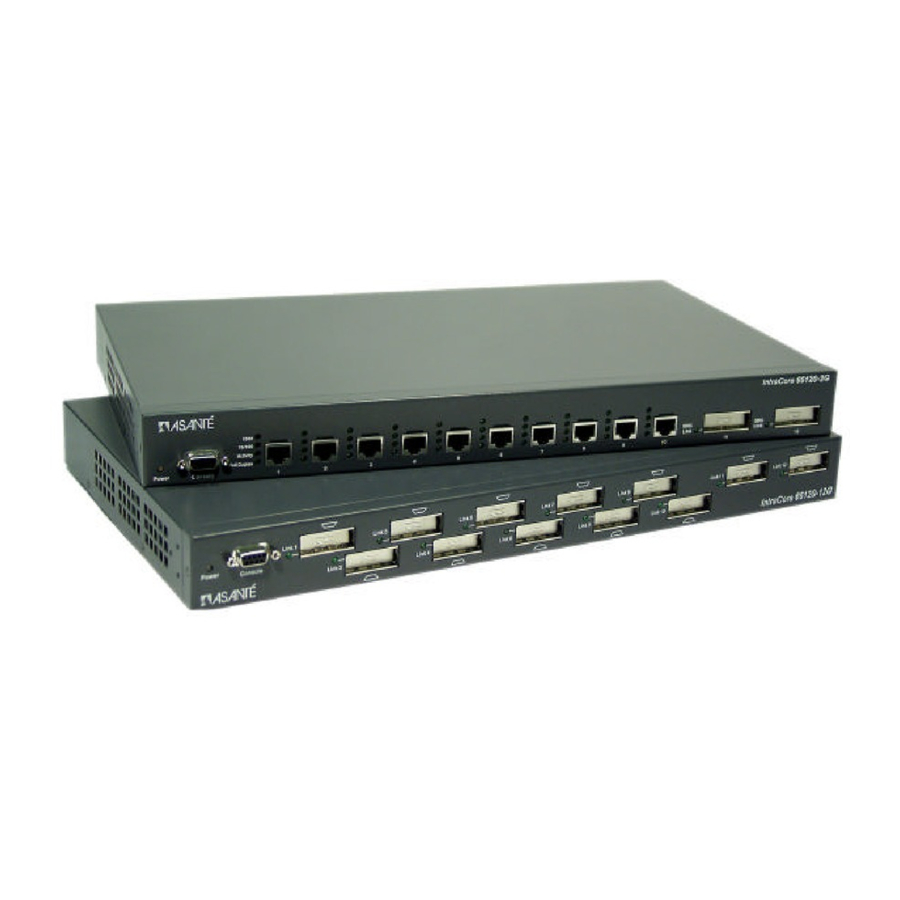
The front panel contains all the Ethernet ports, Console port, and LEDs. There is one System LED, four LEDs for each copper port (model 65120-2G only), and one LED for each GBIC port. Detailed definitions can be found Table 1-1. -
Page 7: Led Definitions
1.2 LED Definitions The following Table describes the LEDs, which allows monitoring of the status of your switch: Port Power/System Green Amber 10/100/1000 1G Link Green 10/100/1000 10/100 Link Green 10/100/1000 Activity Blinking Green 10/100/1000 FDX/HDX Solid Green Blinking Green GBIC Link Green... -
Page 8: Management
1.3 Management There are three different methods by which a user can manage the switch: web, console/telnet, or SNMP. 1.3.1 Web-Based Interface Users can configure the switch, monitor the LED panel, and display statistics graphically with Netscape Navigator browser version 4.0 or higher and Microsoft IE version 4.01 or higher. With Internet access, users can link directly to the local switch’s home page. -
Page 9: Management Information Bases (Mibs)
1.3.4 Management Information Bases (MIBs) The system supports the following MIBs: 1. MIB II (RFC 1213) 2. Ethernet Interface MIB (RFC 1643) 3. Bridge MIB (RFC 1493) 4. 4 groups of RMON (RFC 1457) The Ethernet Statistics Group The Ethernet History Group The Alarm Group The Event Group 5. -
Page 10: Chapter 2 Installation And Setup
Power Cord Self-adhesive rubber feet for desktop placement Rack mount kit for rack installation IntraCore 65120 CD-ROM with user’s manual, utilities and product information If any of these items are missing, contact your dealer immediately. 2.2 Installation Overview The switch may be installed into an equipment or wall rack, or it may be placed on a level and stable desktop surface. -
Page 11: Installation Into An Equipment Rack
Number 1, number 2 and 3/16-inch flat-blade screwdrivers Antistatic mat or foam 2.2.3 Power Requirements The electrical outlet should be located near the IntraCore 65120 and be easily accessible. It must also be properly grounded. Make sure the power source adheres to the following guidelines:... -
Page 12: Equipment Rack Guidelines
IntraCore 65120 vents. Clearance: In addition to providing clearance for ventilation, ensure that there is adequate clearance for servicing the IntraCore 65120 from the front. 2.3 Setup The following sections describe the various methods for setting up and managing the switch. -
Page 13: Password Protection
2.4 Password Protection The Password Protection feature is disabled by default, allowing immediate access to ANYONE on the network. To protect your switch from unauthorized changes to the configuration, you must enable the protection feature. It can only be enabled through the console interface. To set a password via telnet, follow these steps: Note: Use the arrow keys to move within a menu. -
Page 14: Ip Assignment
Now enter your password, pressing Enter when done. Enter the password again to confirm, pressing Enter when done. Press Ctrl+W to save. 2.5 IP Assignment To assign an IP address (other than the default IP address): From the Main Menu, select a. System Manager. Select b. -
Page 15: Snmp Host Access
Press Ctrl-W when done to save these changes. After making IP changes, the system needs to be reset. Press the Esc key to return to the System Manager Menu. Go to System Manager/Reset. Use the arrow keys to select Yes to proceed with Reset. 2.6 SNMP Host Access When the reset is complete the box should be seen on the network. -
Page 16: Chapter 3 Web-Based Management
Chapter 3 Web-Based Management Web-Based Management allows switch configuration changes to be made using an Internet Web browser. This interface also allows for system monitoring of the Switch. Buttons featured are: Reload: Pulls that screen’s data from current values on the system Apply: Submits change request to system and refreshes screen data Please refer to Chapter 6 Switching Concepts to review any features that are not familiar to you. -
Page 17: Introduction
3.2 Introduction This page briefly describes the web-based management features, device management and Interface operation. It contains a product overview and product features. 3.3 System Manager The system manager contains all system operations and general information. It is organized with several sub-folders: General Info: General system information and administration IP Settings: IP parameters... - Page 18 3.3.2 IP Settings There are three tunable parameters to be set by the system administrator: Enter site-specific IP address, Gateway address and Network mask Click Apply to change the IP settings Save Configuration to NVRAM and reset the system to implement the changes 3.3.3 NVRAM Admin After making any changes to the screens within the Web Interface, users must save the changed settings to Non-Volatile Random Access Memory (NVRAM).
-
Page 19: Firmware Update
3.3.4 Firmware Update On the Firmware Update screen, the system can be configured to download and boot from a new image off the network (Please refer to Chapter 5 when updating software). Choose from the following options: Net option: This option allows the user to try out a new image before upgrading. It requires a TFTP server and a server IP address to retrieve the specified image from the given IP address. -
Page 20: Port Manager
3.4 Port Manager This page will allow access to the port parameters. The configurable parameters are available as follows: Port Name Port Enable Auto Negotiation Operating Parameters Flow Control HOL Blocking 3.5 Address Manager The Address Manager allows you to add or remove static address entries as well as change the dynamic address aging times. -
Page 21: Address Aging
Remove an existing entry: Highlight that entry in the table, by clicking on the MAC address Choose Remove 3.5.2 Address Aging Aging Time is a variable that must be configured. Its purpose is to determine the amount of time an entry is held in the forwarding tables. -
Page 22: Port Settings
3.6.2 Port Settings For the Port Settings options, you can specify spanning tree parameters for each port. These parameters include port priority and path cost 3.7 VLAN Setup The VLAN tagging option is a standard set by the IEEE to facilitate the spanning of Virtual Local Area Networks (VLANs) across multiple switches (Reference: IEEE standard 802.1Q-1998 Virtual Bridged Local Area Networks). -
Page 23: Port Trunking
Add VLAN Membership: Select the VLAN you want to modify Click the box below the port number on the line of the VLAN, so that a “T” (tagged) or “U” (untagged) appears Remove VLAN Membership: Click the box again until a blank box appears. This will remove VLAN membership from the port 3.7.2 Port VLAN ID (PVID) Settings All untagged packets entering the switch will by default be tagged with the ID specified by the port’s PVID. -
Page 24: Port Mirroring
3.9 Port Mirroring Port mirroring is a feature to help in the debugging of a network. This web interface page allows enabling or disabling of port mirroring and the setting of source and monitor ports. The Monitor port will show a copy of every packet that arrives or leaves the source port. -
Page 25: Host Table
3.10.2 Host Table The SNMP Host Table screen allows you to add and remove hosts from access rights that have been granted to community groups. The permissions GET, SET and TRAP are assigned to a community name and then these permissions are assigned to individual machines by adding those machines and their IP address to the appropriate community string. -
Page 26: Igmp (Internet Group Management Protocol) Management
3.11 IGMP (Internet Group Management Protocol) Management IGMP is the Internet control protocol used by IP hosts to report their multicast group memberships to any neighboring multicast router. Enable IGMP to achieve automatic multicast filtering for efficient bandwidth utilization. 3.12 Statistics The statistics page allows the administrator to chart different system data. -
Page 27: Group Chart
3.12.2 Group Chart This chart tracks the types of errors that have occurred on one port. Enter the port selection, the refresh rate and the color. When all of the variables are set, click Draw. Click Reset to start again. 3.12.3 History Graph This page will graph data over time, allowing you to compare each port’s activity. -
Page 28: Chapter 4 Console Interface
Chapter 4 Console Interface The console, using VT100 terminal emulation, can be accessed from the RS232 serial port or a telnet connection. The switch offers password protection for this interface. All of the following examples of the Console’s User Interface show a screen capture from a telnet session. When attached to the User Interface via a telnet session, make sure that your telnet application is configured to use VT100 emulation. -
Page 29: System Manager
4.4 System Manager This menu contains all the options needed for basic configuration of the switch. Menu items are: General Info IP Settings Security Admin NVRAM Admin Firmware Update Reset 4.4.1 General Info This screen displays the following: System Description System Name- user definable System Contact-user definable System Location-user definable... - Page 30 4.4.4 Non-Volatile Random Access Memory (NVRAM) Admin This screen allows the user to save any configuration changes that are made, or to restore the default settings (choosing Restore Defaults without Boot Parameters will reset most defaults, but not the IP address and boot loader configuration).
-
Page 31: Port Manager
4.5 Port Manager The Port Manager screen allows the user to arrange the port characteristics related to link operations. Select a. All Ports to arrange multiple port configurations, or b. Port Specific to configure one port at a time. Use the spacebar to toggle between selections. -
Page 32: Spanning Tree
4.6.2 Address Aging Aging Time is a variable that must be configured. Its purpose is to determine the length of time an entry is held in the forwarding tables. The default value is set at 300 seconds (5 minutes). The Administrator may change this value to any value between 10 and 1,000,000 seconds. -
Page 33: Vlan Setup
4.8 VLAN Setup The VLAN tagging option is a standard set by the IEEE to facilitate the spanning of VLANs across multiple switches (Reference: IEEE standard 802.1Q-1998 Virtual Bridged Local Area Networks). 4.8.1 VLAN Administration In this screen the user can add new VLAN groups by entering the VLAN ID and name. -
Page 34: Port Mirroring
4.10 Port Mirroring Port Mirroring is a feature to help in the debugging of a network. This screen allows for the enabling or disabling of port mirroring and the setting of source and monitor ports. The monitor port will show a copy of every packet that arrives or leaves the source port. -
Page 35: Internet Group Management Protocol (Igmp) Management
4.12 Internet Group Management Protocol (IGMP) Management IGMP is the Internet control protocol used by IP hosts to report their multicast group memberships to any neighboring multicast router. Enable IGMP to achieve automatic multicast filtering for efficient bandwidth utilization. 4.13 Statistics This screen views the statistics for each port. -
Page 36: Chapter 5 Firmware Update Procedure
Chapter 5 Firmware Update Procedure The application firmware is field-updateable. The update procedure and the required equipment are described in this chapter. Note: Once the system is up, it is controlled by an executing application image residing in the flash memory. No firmware update is possible during this mode. -
Page 37: Chapter 6 Switching Concepts
Chapter 6 Switching Concepts The following sections provide brief explanations of some of the concepts related to switching. If more information is required, please refer to networking textbooks, online resources (i.e. www.oreillynet.com) or your MIS manager. 6.1 Spanning Tree Protocol The Spanning Tree Protocol (STP) is part of the IEEE 802.1D standard. -
Page 38: Spanning Tree Port Configuration
Forward Delay After a recalculation of the spanning tree, the Forward Delay parameter regulates the delay before each port begins transmitting traffic. If a port begins forwarding traffic too soon (before a new root bridge has been selected), the network can be adversely affected. The default value for Forward Delay is 15 seconds. Note: The above parameters (Hello Time, Maximum Age and Forward Delay) are constrained by the following formula: (Hello Time + 1) <= Maximum Age <= 2 x (Forward Delay –... -
Page 39: Flow Control
6.2.2 Flow Control With a link operating at a high data rate, a switch may experience occasional limitations in the buffer space used to store Ethernet frames before forwarding them. In this situation, if the sending station continues to send frames, the switch will have no option but to discard the frames. This may quickly lead to unacceptable delays in upper-level protocols. -
Page 40: Appendix A: Troubleshooting
Appendix A: Troubleshooting In the unlikely event your network does not operate properly, follow the troubleshooting tips below: CHECK YOUR POWER CONNECTION. Is the Power LED on? If not plug the power cord into another known working AC outlet. CHECK YOUR NETWORK CABLE. Are the LINK LEDs on? If not, check the cable connections. Are the connectors seated correctly in each port? Make sure that the correct type of cable is connected to each port. -
Page 41: Appendix B: Vlan Description And Examples
Appendix B: VLAN Description and Examples Packets received by the switch will be treated in the following way with regard to the Switch’s VLAN settings: When an untagged packet enters a port, it will be automatically tagged with the port’s default VLAN ID tag number. - Page 42 To allow untagged packets to participate in the ‘New’ VLAN, make sure to change the Port VLAN IDs for the relevant ports. To access the Port VLAN ID page choose c. PVID Settings from the VLAN Setup menu. Use the space bar to add an ‘X’ indicating which PVID is assigned to which port.
- Page 43 The specific ports shown above have the following Port VLAN ID settings (The Port VLAN ID settings for each port are configured in their respective Port Specific screen (in the Port Manager Menu) or in the VLAN Administration page): Port 01: 2 Port 05: 5 Port 09: 10 Port 02: 15...
-
Page 44: Appendix C: Features, Defaults And Specifications
Password: Asante (default) IP Address: 192.168.0.1 (default) The following is a summary of features of the 65120 Series Gigabit Ethernet Switch: Model 65120-12G: 12 1000Base GBIC ports, which supports 802.3z Gigabit Ethernet 1000BaseSX or LX, and 802.3ab Gigabit Ethernet 1000BaseT Model 65120-2G: 10 Gigabit Ethernet switched ports with RJ-45 Twisted Pair (TP) connectors, which supports 10/100/1000BaseT Ethernet. - Page 45 Supports up to 64 virtual LANs 17-inch and standard 1U chassis high Internal power supply...
-
Page 46: Appendix D: Fcc Compliance And Safety Statements
Appendix D: FCC Compliance and Safety Statements FCC Compliance Statement This equipment generates and uses radio frequency energy and if not installed and used properly, that is, in strict accordance with the instructions provided with the equipment, may cause interference to radio and TV communication. -
Page 47: Appendix E: Online Warranty Registration
Appendix E: Online Warranty Registration Before calling Asanté Technical Support, please register your switch online at www.asante.com/support/registration.html. By doing so, you’ll be entitled to special offers, up-to-date information and important product bulletins.
Need help?
Do you have a question about the IntraCore 65120 Series and is the answer not in the manual?
Questions and answers