
Subscribe to Our Youtube Channel
Related Manuals for Valore SUMMIT VSU-E30CS


Summary of Contents for Valore SUMMIT VSU-E30CS
- Page 1 SUMMIT VSU-E30CS VSU-E36CS PLATEAU VPL-E30AS VPL-E36AS Model number: Serial Number: NOV14.0601...
- Page 3 SAFETY NOTICE ..............LIST OF MATERIALS ............INSTALLATION Ducting Calculation Sheet ........Mounting Height & Clearance ........ Ducting Options ......................Mounting the Hood VSU .......... Mounting the Hood VPL ......... 11 Ductless Recirculating ..........FEATURES & CONTROLS Touch Glass Controls, VSU ........
- Page 4 READ AND SAVE THESE INSTRUCTIONS WARNING TO REDUCE THE RISK OF FIRE OR ELECTRIC SHOCK, DO NOT USE THIS FAN WITH ANY SOLID-STATE CONTROL DEVICE. WARNING TO REDUCE THE RISK OF FIRE ELECTRIC SHOCK, OR INJURY TO PERSONS, OBSERVE THE FOLLOWING: a.
-
Page 5: Operation
WARNING TO REDUCE THE RISK OF FIRE, USE ONLY METAL DUCTWORK. CAUTION attics, crawl spaces or garages. OPERATION and loose clothing. The manufacturer declines all responsibility in the event of failure to observe the instructions given here for installation, maintenance and suitable use of the product. The manufacturer further declines all responsibility for injury due to negligence and the warranty of the unit automatically expires due to improper maintenance. -
Page 6: Hardware Package Contents
MODELS: VSU, VPL PARTS SUPPLIED 1 - Hood with internal blower 1 - Duct cover wall bracket 1 - Duct cover assembly (top and bottom) 1 - 6” round backdraft damper (pre-installed) 2 - 50W GU-10 halogen light bulbs 2 - Aluminum mesh filters 1 - Hardware package HARDWARE PACKAGE CONTENTS (3) M4 x 1-1/2”... - Page 7 Equivalent number Equivalent number Duct pieces Duct pieces length x used T otal length x used T otal 3- 1/ 4” x 10” 1 Ft. 6”- 8” Round 30 Ft. Rect., wall cap straight with damper 7” Round, 1 Ft. 6”- 8”...
-
Page 8: Damage - Shipment/Installation
Minimum mount height between range top to hood bottom should be no less than 26”. Maximum mount height should be no higher than * Min. ducted (A) 34”. Min. recirc. (B) Max. It is important to install the hood at the proper mounting height. - Page 9 WARNING FIRE HAZARD NEVER exhaust air or terminate duct work into spaces between walls, crawl spaces, ceiling, attics or garages. All exhaust must be ducted to the outside, unless using the recirculating option. Use single wall rigid Metal ductwork only. Some Ducting Options Roof Pitch w/ Flashing &...
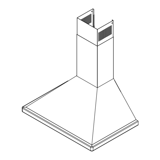
- Page 10 Standard Duct Cover Min. ducted 27 ” Min. recirc. 32” Max. ducted 42 ” V1C-00SU Extension Min. ducted 46 ” Min. recirc. ” Max. ducted 80”...
- Page 11 Standard Duct Cover Min. ducted 27” Min. recirc. 31” Max. ducted 48” V1C-00PL Extension Min. ducted 43 ” Min. recirc. ” Max. ducted 81”...
-
Page 12: Mounting The Hood Vsu
CAUTION: At least two installers are required due to the weight and size of the hood. Duct Cover Bracket 1. Measure from range top to hood bottom and mark line A. 2. Plum and mark center line. 3-1/2" 2" 4. Mark mounting spread from C/L on line B. From center 12 1/4"... -
Page 13: Cable Lock
CAUTION: At least two installers are required due to the weight and size of the hood. 1. Measure from range top to hood bottom and mark line A. 2. Plum and mark center line. do not tighten all the way. Note: wood blocking may need to be added behind the drywall if no studs are 18-7/16 present. - Page 14 Ductless recirculation is intended for applications where an exhaust duct work is not possible to be installed. When converted, the hood functions as a recirculating hood rather than an exhaust hood. Fumes and exhaust circulated back within the home. We recommend to ALWAYS exhaust air outside of the home by employing existing or installing new duct is not possible should you recourse to converting the hood into a recirculating hood.
-
Page 15: Features/Controls
Delay Off Timer Indicator Speed Indicators Lights On/Off Power / Delay Off Lights Indicator clean filters Fan Speed Increase Clean Filter Indicator Fan Speed Decrease Power / Delay Off Button Button will turn power on and off for entire hood (fan and lights. - Hood will remember the last speed and light level it was last turned off at. - Page 16 Blower On/Off Lights Bright/Dim/Off Blower Speed Selection Delay Off Timer Blower On/Off Press to turn blower on and off. If lights are on they will also switch off when this button is pressed. Blower Speed Selection Press to cycle through blowers speeds I, II and III Lights Bright/Dim/Off Press to cycle through light levels Bright, Dim and Off...
-
Page 17: Hood And Filter Cleaning
SURFACE MAINTENANCE: Clean periodically with hot soapy water and clean cotton cloth. Do not use corrosive or abrasive detergent , or steel wool/scouring pads which will scratch and damage surface. For heavier soil use liquid degreaser. After cleaning it is recommended that you use non-abrasive stainless steel polish/cleaners, to polish and buff out the stainless luster and grain. -
Page 18: Replacing Light Bulbs
REPLACING LIGHT BULBS CAUTION: Light bulb becomes extremely hot when turned on. DO NOT touch bulb until switched off and cooled. Touching hot bulbs could cause serious burns. Make sure all power is turned off and bulbs are not hot. stops and falls out. - Page 19 TROUBLESHOOTING PROCEDURES FOR VSU AND VPL Issue Cause What to do After installation, 1. The power source is not turned ON. 1. Make sure the circuit breaker and the unit’s the unit doesn’t power is ON. work. 2. The power line and the cable locking connector 2.
- Page 20 DESCRIPTION PART# Replacement Parts Optional Accessories Order replacement parts and accessories by calling 1.888.750.1698...
-
Page 21: Limited Warranty
1-888-750-1698 Valore (referred to herein as “we” or “us”) warrants to the original consumer purchaser (referred to herein as “you” or “your”) of Valore products (the “Products”) that such Products will be free from defects in materials or workmanship as...
Need help?
Do you have a question about the SUMMIT VSU-E30CS and is the answer not in the manual?
Questions and answers
replacing the filters , Where can we purchase replacement filters ? and are there similar non branded ones that can be used as well for easy purchase such as in Home depot style stores instead of online?
Replacement filters for the Valore SUMMIT VSU-E30CS can be purchased according to the specified part number in the manual. The recirculating kit for VSU-ExxCS models is VRC-01SU, which includes two filters and brackets. The manual does not mention the availability of non-branded alternatives in stores like Home Depot.
This answer is automatically generated