Magellan eXplorist XL User Manual
Gps satellite navigator
Hide thumbs
Also See for Magellan eXplorist XL:
- Quick reference manual (14 pages) ,
- Reference manual (91 pages)
Table of Contents
Advertisement
Advertisement
Table of Contents

Related Manuals for Magellan Magellan eXplorist XL


Summary of Contents for Magellan Magellan eXplorist XL
- Page 1 Magellan GPS Satellite Navigator User Manual Meridian XL...
-
Page 2: License Agreement
USE PROPER ACCESSORIES Use only Magellan cables and antennas; the use of non-Magellan cables and antennas may severely degrade performance or damage the receiver, and will void the warranty. -
Page 3: Table Of Contents
Introduction ... 1 Packing List ... 1 Conventions Used In This Manual ... 2 Getting Started ... 3 General Description ... 3 Connecting Receiver Power ... 4 First Time Use - Initializing the Receiver ... 5 Proper Handling - Signal Reception ... 9 Taking your First Fix ... - Page 4 Viewing a Waypoint ... 27 Accessing the Waypoint Function Menu ... 28 Projecting a Waypoint ... 28 Editing a Waypoint ... 29 Deleting a Waypoint ... 30 Routes ... 31 Activating a GOTO Route ... 31 Accessing the Route Menu ... 32 Creating a Multileg Route ...
- Page 5 Power Lock ... 47 Light Intensity ... 48 Contrast ... 48 Additional Features ... 48 Viewing the SAT STATUS Screen ... 48 Viewing the Odometer ... 49 Resetting the Odometer and/or Trip Odometer ... 49 Viewing the Clock ... 49 Setting Alarms ...
- Page 6 Menu Cross-Reference Guide This guide displays the menus found in the Meridian XL and the page number of this manual that the operation is described. Function Menu SAT STATUS ... ROUTE MENU ... WAYPOINTS ... SETUP ... SIMULATOR ... ODOMETER ... LAST FIXES ...
- Page 7 SETUP Menu INITIALIZE ... COORD SYSTEM .. ELEV MODE ... TIME FORMAT ... VELOCITY AVG .. SPEED UNITS ... DIST UNITS ... ELEV UNITS ... NORTH REF ... MAP DATUM ... NMEA ... BAUD RATE ... WPT SORT ... LFIX INTERVAL . PLOT SETUP ...
- Page 8 Welcome from the Magellan crew. With the purchase of a Magellan GPS satellite receiver, you have joined the thousands of people who enjoy using GPS in their professional and recre- ational activities. Since we introduced our first product more than five years ago, Magellan has established a reputation for product excellence and customer support.
-
Page 9: Introduction
The following items should be in your package: GPS satellite navigator User Manual Reference Guide Additional Items Carrying case Lanyard strap Mounting bracket Power Cord If any of these items is missing, please contact your local Magellan dealer or distributor. -
Page 10: Conventions Used In This Manual
NOTE: Note messages are shown to provide important informa- tion that will assist you in understanding your Magellan receiver and its operation. If you are following along with your receiver during the step-by-step instructions, you should make key presses whenever the key name is in bold text. -
Page 11: Getting Started
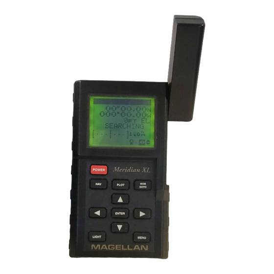
Getting Started General Description The Meridian XL is a self-contained hand-held GPS receiver designed for general purpose position locating and navigation. It has a removable quadrifilar antenna located on the upper right side of the receiver, a high- contrast backlit LCD, and keypad. Using three AA batteries, inserted from the battery door found behind and near the base of the receiver, the Meridian XL will operate continuously for up to 6 hours. -
Page 12: Connecting Receiver Power
Connecting Power to the Meridian XL. The Meridian XL receiver operates on either three AA batteries or a 9-16 volt DC external power source. Before using the Magellan Meridian XL GPS receiver, you need to install the batteries by removing the battery compartment door as shown. -
Page 13: First Time Use - Initializing The Receiver
First Time Use - Initializing the Receiver You do not need to initialize your receiver each time you use it. Follow these steps to initialize the Meridian XL if this is the first time you are using it, if the receiver memory has been cleared or if the receiver has been transported more than 300 miles while turned off. - Page 14 If you inadvertently press another key without initializing manually, the receiver displays the POSITION screen with null values for the latitude and longitude (00 00.00N, 000 00.00W). In this case, the receiver will self-initialize, which may take 15 minutes or more. The elevation mode will automatically switch from 2D to 3D, which is necessary to obtain a proper first fix.
- Page 15 If this is not the first time you have used your receiver, or if it is the first time but your receiver has already begun acquiring satellite signals, the following time and date entry may not be displayed. Input your local time. Take extra care to input the time correctly within including...
- Page 16 Press the UP ARROW. Notice that the highlighted number has incremented by one. Keep pressing the UP ARROW until the first digit matches the first number you found for latitude. If you go past the number you want, you can use the DOWN ARROW to step down or continue using the UP ARROW and loop through the number...
-
Page 17: Proper Handling - Signal Reception
The receiver will prompt you for your local elevation, time and date. Use the UP/DOWN and RIGHT/ LEFT ARROWs to enter these as described above; press ENTER to confirm each screen. The receiver is now ready to perform one of its primary functions, providing you with your current position. -
Page 18: Taking Your First Fix
Taking your First Fix To get a position fix, you must be outside with a clear view of the sky and away from any large obstructions (buildings, large trees, etc.). Rotate the antenna upward and hold the receiver in a comfortable position. If the receiver is off, press the POWER key to turn the receiver on, or if you have just finished initializing the receiver, press the NAV key until the screen showing your coordinates is displayed. - Page 19 Press NAV or PLOT (which will take you to a NAV or PLOT screen if you are not already there), then press ENTER, highlight SAVE POS and press ENTER. This tells the receiver that you want to store the current position as a waypoint. The cursor is in the upper left corner, and the arrows displayed in the lower right corner of the screen indicate that...
- Page 20 Selecting CREATE WPT instead of SAVE POS will allow you to enter a waypoint exactly as described above with the additional option of changing the latitude, longitude, and elevation of the position. (See Creating Waypoints) Press the RIGHT ARROW. This moves the cursor one space to the right.
-
Page 21: Introduction To Routes
Introduction to Routes A route is a planned course of travel defined by a series of waypoints. To create a route, you select waypoints that you have stored in the receiver’s memory. These waypoints are then connected to form the segments or “legs”... -
Page 22: Creating A Goto Route
If the receiver has not yet computed a position fix, then the start of the GOTO may not represent your current position. It will, however, correct the navigation information after a position fix is acquired. Creating a GOTO Route After computing a position fix, press GOTO. -
Page 23: Reference Section
Press the POWER key and hold for three seconds. If the batteries are installed correctly or the external power is properly connected, the copyright and Magellan displays will quickly flash on the screen, followed by the POSITION screen (if the unit has been initialized) or by the message UNIT IS NOT INITIALIZED PRESS ENTER TO INTIALIZE. -
Page 24: Inputting Data
Inputting Data The UP/DOWN and LEFT/RIGHT ARROWs have two functions depending on how the ARROW ICONS are displayed in the bottom right corner of the various screens. Moves the cursor one space , left or right While on some screens the UP/DOWN or LEFT/RIGHT ARROWs are used to access additional pages, on other screens they allow you to input data, such as waypoint names or coordinates, or to select menu items. -
Page 25: Nav Screens
NAV Screens The three NAV screens accessible from the NAV key are the POSITION, NAV 1 and NAV 2 screens. You may scroll through these screens using the NAV key or the UP/DOWN ARROWs. Press NAV until the POSITION screen is displayed. -
Page 26: Viewing The Nav 1 Screen
Viewing the NAV 1 Screen Press the NAV key until the NAV 1 screen appears, showing BRG, DST, COG and SOG. NAV 1, the first navigation screen, provides you with information about your speed and direction of movement. If a route is active, the NAV 1 screen also tells you where you are in relation to the destination and courseline, and displays the name of the destination waypoint of the active leg in the title bar. -
Page 27: Customizing The Nav Screens
Current Destination Bearing to Destination Course Over Ground * Cross Track Error * Displays dashes if receiver is stationary (<1 knot) Information is displayed in a large format so that it may be easily viewed from a distance. All of the fields can be customized; default fields include bearing (BRG) to the active waypoint, course over ground (COG) and cross track error (XTE), or you may select VMG (velocity made good), SOA (speed of advance), SOG (speed over ground), ETA (estimated time... - Page 28 Press the NAV key from any screen to view a NAV screen. Press NAV again as necessary to display either the NAV 1 or NAV 2 screen. Press ENTER to display the pop-up menu. Use the UP/DOWN ARROWs to highlight CUSTOMIZE and press ENTER.
-
Page 29: Plot Screens
PLOT SCREENS Three graphical screens can be accessed from the PLOT key: the PLOT screen, the ROAD screen and the POINTER screen. You may scroll through these three screens by pressing the PLOT key repeatedly once you have accessed one of the PLOT screens or by using the UP/DOWN ARROWs. Press ENTER from any of these three screens to display the pop-up menu. -
Page 30: Changing The Plotter Scale
The PLOT screen displays “TO destination waypoint” of the current leg if there is an active route or GOTO, and the bearing and distance to that waypoint. Current Destination Bearing to Destination Near Waypoint Icon Changing the Plotter Scale Press the LEFT/RIGHT ARROWS to adjust the scale, shown at the bottom left corner of the screen. -
Page 31: Setting A Goto Using Pan N Scan
When the cursor covers a waypoint icon on the screen, the title bar displays the name of that waypoint and, just below, the bearing and distance to the waypoint. Setting a GOTO Using PAN N SCAN When the cursor is on an icon and the waypoint name is displayed, press ENTER. -
Page 32: Viewing The Road Screen
Viewing the ROAD Screen Access the ROAD screen by pressing the PLOT key (two or three times, if necessary). This is the navigation CDI screen. As with the preceding screen, the bearing and distance to the leg destination are displayed. Current Destination Bearing to... - Page 33 From any NAV or PLOT screen, press ENTER, highlight SAVE POS and press ENTER. This tells the receiver that you want to store the current position as a waypoint. The cursor is in the upper left corner of the display and the highlighted arrow icons indicate that it is in the edit mode.
-
Page 34: Creating A Waypoints
Creating a Waypoints This allows you to create and store a waypoint with a receiver-generated name or a user-assigned name and allows you to assign the position coordinates. From any ENTER NAV or PLOT Screen From any NAV or PLOT screen, press ENTER, highlight CREATE WPT and press ENTER. -
Page 35: Viewing A Waypoint
To access the Waypoint Menu, press MENU. Use the UP/DOWN ARROWs to select WAYPOINTS and press ENTER. This will take you to the WPT MENU screen. This is a listing of all the waypoints you have stored in your receiver. As the number of waypoints in the library increases, the WPT MENU screen will add a second column of four waypoint names to the right of the ones you have now, and will continue to another “page.”... -
Page 36: Accessing The Waypoint Function Menu
Accessing the Waypoint Function Menu Highlight MENU WAYPOINTS Press ENTER Press MENU, use the UP/DOWN ARROWs to select WAYPOINTS and press ENTER. Select a waypoint from the list and press ENTER to access the WAYPOINT screen, press ENTER again to access a menu of functions that may be performed on the selected waypoint. -
Page 37: Editing A Waypoint
Use the UP/DOWN and LEFT/RIGHT ARROWs to key in the distance at which you wish to project the new waypoint. When you have finished, press ENTER to confirm and continue. The cursor appears in the bearing field (BRG). Use the UP/DOWN and LEFT/ RIGHT ARROWs to key in the bearing at which you wish to project the new waypoint. -
Page 38: Delete
Changing the name of the waypoint is the first option. Use the LEFT/ RIGHT ARROWs to move the cursor and the UP/DOWN ARROW to select the characters. After changing the waypoint name or if there are no changes to the waypoint name, press ENTER. Make a changes to the position using the UP/DOWN ARROWs to scroll through the number list, and use the LEFT/RIGHT ARROWs to move left and right. -
Page 39: Routes
ROUTES A route is a planned course of travel defined by a series of waypoints. To create a route, you must already have waypoints stored in the receiver’s memory. These waypoints are then connected to form the segments or “legs” of the route. A route may contain from one to fifteen legs. Activating a GOTO Route The GOTO function enables you to create a simple one-leg route from your present position to a defined waypoint. -
Page 40: Accessing The Route Menu
Accessing the Route Menu The Route Menu is used to create and view up to five single or multi- leg routes. A pop-up menu allows you to activate, deactivate, or reverse a selected route, edit or view the legs of the route, or clear the route. The ROUTE MENU can be accessed in three ways: Press MENU, use the UP/DOWN ARROWs to select ROUTE MENU in the... - Page 41 Access the ROUTE MENU. Use the UP/ DOWN ARROWs to select an EMPTY route and press ENTER. If there are no EMPTY routes in the ROUTE MENU, you must clear a route before you can create a new one. Use the LEFT/RIGHT ARROWs to select the FROM waypoint and press ENTER.
-
Page 42: Activating And Deactivating A Route
The display returns to the Route Menu. The new route is now the active route, and can be viewed on the NAV and PLOT screens. The receiver will not accept TO waypoints having the same or nearly the same coordinates (within 0.1 distance units) as the FROM waypoint. -
Page 43: Viewing The Route Summary (Edit Option)
Viewing the Route Summary (Edit Option) The edit option displays a summary of the selected route, including starting and ending waypoints, number of legs, and total distance. It allows you to view, insert, delete and replace individual legs of a route, as well as choose the leg on which you want to navigate by making this the current active leg. -
Page 44: Deleting A Leg
Access the ROUTE MENU and highlight the route to insert a leg into. Press ENTER to bring up the pop-up menu, highlight EDIT, and press ENTER. Use the UP/DOWN ARROWs to view the route leg in which you want to insert a waypoint, press ENTER to access the EDIT LEG menu, select INSERT, and press ENTER. -
Page 45: Adding A Leg
The receiver gives you one last chance to change your mind. Press ENTER to confirm. The leg is removed from the route. function key to abort the process. Adding a Leg You can add a leg to the end of the route in much the same way as you would insert a leg, only this time you add a waypoint to extend the end of the route beyond the original destination. -
Page 46: Replacing A Waypoint
Replacing a Waypoint This allows the destination (TO) waypoint of a leg to be changed to a different waypoint. Use ARROW KEYS Access the to highlight route to ROUTE MENU ENTER Access the ROUTE MENU and highlight the route to be edited. Press ENTER to bring up the pop-up menu, highlight EDIT, and press ENTER. -
Page 47: Deleting A Route
Use ARROW KEYS Access the to highlight route to ROUTE be edited MENU ENTER Access the ROUTE MENU and highlight the route to be edited. Press ENTER to bring up the pop-up menu, highlight EDIT, and press ENTER. Use the UP/DOWN ARROWs to view the leg to be activated. Press ENTER to access the EDIT LEG menu, select NAVIGATE, and press ENTER. -
Page 48: Creating A Backtrack Route
The MOB position and MOB route information will be lost when the receiver is turned off. Creating a Backtrack Route This creates a route using fixes in the Last Fix Buffer (up to 16 of the most recent last fixes) to create a route that “backtracks” the course you last took. -
Page 49: Viewing The Last Fix Trip Summary Screen
The receiver immediately begins navigating toward the selected coordinates. The display returns to the last viewed NAV screen and the words TO COORD appear in the title bar. The COORD position and COORD route information will be lost when the receiver is turned off. Last Fix Buffer While you are taking position fixes your receiver can automatically save them. -
Page 50: Setup Options
Press MENU and use the UP/DOWN ARROWs to highlight LAST FIXES and press ENTER. Use the LEFT/RIGHT ARROWs to select any Last Fix except +LFX01. Press the UP ARROW. Use the LEFT/RIGHT ARROWs to select any of the other fixes present in the last fix buffer that were taken after the one chosen as the “FROM”... -
Page 51: Setting The Coordinate System
Setting the Coordinate System The coordinate system you ultimately select will depend on the maps or charts that you are using with your receiver. The default coordinate system is LAT/LON, DEG/MIN.00. Highlight MENU SETUP Press ENTER If you select LAT/LON, you will be asked to select one of three formats for displaying position coordinates: DEG/MIN.00, DEG/ MIN.000 or DEG/MIN/SEC. -
Page 52: Selecting Time Display
Selecting Time Display Your Magellan receiver can display time in one of three formats: local 24-hour (military), local 12-hour (AM/PM), or UT (Universal Time or Zulu). The default Time Display is LOCAL AM/PM. Highlight MENU SETUP Press ENTER If either local time format is... -
Page 53: Setting Distance Units
To use NMEA your receiver must be connected to the NMEA device with the Power/Data Cable and the device you’re using must accept the proper 0183 format. Your GPS receiver must be on and computing fixes before NMEA information will be output through the data port. -
Page 54: Selecting Baud Rate
An optional Power/Data Cable is available for the Meridian XL from your local dealer or directly from Magellan Systems. Keep in mind that in order to support the NMEA device, your receiver must be operating continuously. To prevent outages due to low batteries, external power is recommended. -
Page 55: Sampling
MENU Press ENTER Use LEFT/RIGHT ARROWS to select TRACK; OFF, 0.1, Sampling Sampling causes the receiver to turn itself on every 10 minutes, 20 minutes, 30 minutes, or 1 hour, compute a position fix, store the fix in the last fix buffer, and then turn itself off. Highlight MENU SETUP... -
Page 56: Sat Status
Note that the POWER LOCK feature remains active until it is turned off under SETUP. Light Intensity LIGHT INTEN. allows you to select the brightness level (HIGH or LOW) of the display. The light can be switched on and off by holding down the “LIGHT”... -
Page 57: Viewing The Odometer
Press ENTER to return to the Function Menu. Setting Alarms Your Magellan receiver has the ability to sound an external alarm when you arrive at your destination (ARRIVAL); have moved a predefined distance from the place where you set your anchor (ANCHOR); and/or if your cross track error is greater then the defined radius (XTE). -
Page 58: Viewing The Sun/Moon Screen
With the alarm menu displayed, you can turn an alarm on or off by pressing the ENTER key. If you turn on the ANCHOR, XTE or arrival alarms, you will have the option of changing the radius of the selected alarm. The default is set at 200 feet. -
Page 59: Simulator
Simulator The simulator mode causes the receiver to create a fictitious route from your location to two newly created waypoints. You will find the Simulator very handy when you want to review or practice using your receiver at home. In the simulate mode you can watch the receiver simulate movement and observe how the different navigational screens respond. -
Page 60: Delete All Waypoints From Waypoint List
Delete All Waypoints from Waypoint List DELETE WPTS will delete all of the waypoints in your waypoint list. If routes currently exist, deleting waypoints requires that all routes be deleted and a message will be displayed. See Deleting Routes. Highlight MENU CLEAR MENU Press ENTER... -
Page 61: Status Line Icons
Status Line Icons Status appear on most screens and provide you with some valuable information as to the status of the position fixes that are being computed. Most information on this line will be represented by icons which appear before the arrows on the right side of the status line. These arrows have two functions, depending on how they are displayed. -
Page 62: Troubleshooting
Troubleshooting frozen display, keypad does not respond no power Use only the Magellan Power/Data Cable to connect the receiver to external power. position fix doesn’t change position fix fluctuates NMEA device is not responding Remove power and wait for the receiver to turn off. -
Page 63: How To Contact Customer Service
Friday, from 8 A.M. to 5 P.M., Pacific Standard Time. Faxes can be sent to Customer Service at 909-394-7050. If necessary, you can also return your unit to Magellan for repair. (Please call for assistance first.) If possible, please notify us before shipping the unit by Parcel Post or UPS, and include with the unit a description of the problem and your name and address. -
Page 64: Optional Accessories
Antenna Suction Cup Mount. The Extension Cable and Suction Cup Mount are required to operate with the quadrifilar antenna detached. Do not alter the length of the antenna extension cable or use a non-Magellan cable, as this may adversely affect receiver sensitivity. -
Page 65: List Of Available Datums
List of Available WGS84 World Geodetic System NAD27 North American 1927 NAD83 North American 1983 ADIND Adinda ALASK Alaska ARC50 Arc 1950 ARC60 Arc 1960 ASTRO Camp Area Astro AUS66 Australian Geodetic 1966 AUS84 Australian Geodetic 1984 BOGOT Bogota Observatory BUKIT Bukit Rimpah CAMPO Campo Inchauspe... -
Page 66: Nmea Attachment
NMEA Message Sets Data Transfer Your GPS receiver can be set to output GPS data in the NMEA 0183 format to interface with other marine devices. The dataport must be turned on and the output message format selected in SETUP. -
Page 67: Output Data Format
Time, latitude, longitude, speed over ground, course over ground, and date. Track (magnetic and true) and groundspeed (knots and KPH). OUTPUT DATA FORMAT Autopilot Format A 1 2 3 4 5 6 7 8 APA,A,A,X.XX,L,N,A,A,XXX.,M,CCC OR’ed Blink and SNR Cycle Lock Cross Track, Sense (L = steer left, R = steer Right), N.Mi. -
Page 68: Gga Global Positioning System Fix Data
To Selected Waypoint, Great Circle BWC,XXXXXX,XXXX.XX,N,XXXXX.XX,W,XXX.,T,XXX.,M,XXX.X,N,CCCC UTC of Bearing Lat, N or S of waypoint Long, E or W of waypoint Bearing, True Bearing, Magnetic 10-11 Distance, naut. miles Waypoint identifier Global Positioning System Fix Data GGA, hhmmss.ss,111.11,a,yyyyy.yy,a,x,xx,x.x,x.x,M,x.x, 1213 M,x.x,xxxx*hh UTC of Position Latitude –... - Page 69 Geographic Position — Latitude/Longitude GLL,1111.11,a,yyyyy.yy,a,hhmmss.ss,A*hh Latitude, N/S Longitude, E/W UTC of position Status Generic Navigation Information (immediately follows RMC) RMB,A,X.XX,L,CCCC,CCCC,SSS.SS,N,XXXXX.XX,W,XXX.X,XXX.,XX.X, 13 14 A *XX Status XTE, naut. miles and direction to steer (L or field 2.] Origin waypoint ID Destination waypoint ID Destination Waypoint Latitude (N or S) Destination Waypoint Longitude (E or W) Range naut.
- Page 70 VTG,XXX.,T,XXX.,M,XX.X,N,XX.X,K Track degrees, True Track degrees, Magnetic Speed, knots Speed, kilometers/hour The formats listed are NMEA formats and Magellan receivers may not output all of the information listed for a particular format. (A = valid, V = invalid) (DDMMYY) (Mandatory in this sentence)
-
Page 71: City Reference Chart
City Reference Chart Australia & SW Pacific Adelaide 34 55.00 S Alice Springs 23 42.00 S Apia 13 48.00 S Auckland 36 55.00 S Bourail 21 34.00 S Brisbane 27 28.00 S Canberra 35 17.00 S Coober Pedy 28 56.00 S Dampier 20 45.00 S Darwin... - Page 72 Banghazi 32 07.00 N Bangui 4 22.00 N Beira 19 49.00 S Cairo 30 03.00 N Capetown 33 55.00 S Dakar 14 40.00 N Fés 34 05.00 N Freetown 8 30.00 N Harare 17 50.00 S Kabwe 14 29.00 S Kampala 0 19.00 N Kano...
- Page 73 Miami 25 46.00 N Milwaukee 43 02.00 N Minneapolis 44 58.00 N Montevideo, Uru. 34 53.00 S Nakina 59 12.00 N Nashville, TN 36 09.00 N New York 40 43.00 N Norfolk, VA 36 50.00 N Oklahoma City 35 28.00 N Omaha 41 15.00 N Panama City...
-
Page 74: Abbreviations And Data Terms
Abbreviations and Data Terms EXPLANATION OF DATA TERMS BRG. Bearing is the direction, as measured in de- grees from north in a clockwise direction. The re- ceiver uses either true north or magnetic north, as selected in the Setup Menu. The illustration shows a simple compass rose with the eight cardinal direc- tions noted with their bearing. - Page 75 Comparing the lines from points A and B and from points A that while the boat travelled 34 NM it only moved 30 NM along the courseline. If he moves 30 NM on the courseline in 1 hour, his SOA is 30 knots, whereas SOG would be 34 knots.
-
Page 76: Specifications
Specifications Specifications Size Weight Temperature: Operating Storage Case Antenna Operating Characteristics Accuracy: Position Velocity Speed limit Elevation limit Time to First Fix: Cold start* Warm start* After memory loss Warm start: the receiver has obtained a position fix within the last 2 hours. -
Page 77: Coordinate Systems
(There are 60 seconds to one minute, written as 60"). So a Lat/Lon position coordinate can be expressed in two ways, which your Magellan GPS receiver displays as 25 47.50 or 25 47’30. -
Page 78: Deg/Min
Eastings are an east/west measurement, and correspond roughly to longitude. Northings are a north/south measurement, and correspond to latitude. This chart shows the position of Magellan Systems described in both Lat/ Lon and UTM coordinates. LAT/LON DEG/MIN 34˚06.58N... - Page 79 TD Coordinate System. TDs are indicated on many nautical charts in addition to the LAT/LON marks. They are established lines of position (LOPs) that are determined by the difference in the length of time required to receive Loran-C signals. Many coastal navigators use TDs because Loran is a familiar radio aid navigation and TDs are clearly marked on their charts.
-
Page 80: General Maintenance
DC power source by using the optional Power/Data Cable. Batteries We suggest using AA alkaline batteries to power the receiver. (Magellan Systems recommends Eveready Energizer™ batteries.) Alkaline batteries will power the receiver for 6 hours or more of continuous operation. -
Page 81: External Power
If the receiver is being operated in a covered location (such as a navigation station), you may want to use the optional External Antenna Kit. (Use only a Magellan antenna; the use of a non- Magellan antenna may greatly degrade the performance of the receiver.) -
Page 82: Power/Data Cable Instruction Sheet
Warning - Attach the power/data cable to the port of the black Trailblazer XL, Part No.00-62006-003 and the Black Meridian XL, Part No. 00-12004-000 ONLY. DC POWER SOURCE (10 – 35 VDC) Magellan Cigarette Lighter Adapter connected to 10 – 35 VDC power source [Black with white strip wire is... -
Page 83: The Global Positioning System
Each satellite transmits its own ephemeris data. Both almanac and ephemeris data are required for a GPS receiver to locate and acquire satellites quickly and compute a position fix. 0 0 . 0... - Page 84 This technique requires that your GPS receiver be connected to a compatible differential beacon receiver (such as the Magellan DBR™, which is compatible will all differential-ready Magellan receivers). You must also be within range of a differential radio beacon.
-
Page 85: More Information On Gps
A Comprehensive Guide to Land Navigation with GPS An excellent book written by Noel J. Hotchkiss and published by Alexis Publishing. ISBN No: 0-9641273-2-6. This book uses the Magellan Trailblazer to discuss and describe land navigation with a GPS receiver. - Page 86 GPS World Magazine Monthly magazine covering a wide variety of uses for GPS receivers. Advanstar Communications 859 Willamette Street Eugene, Oregon 97401 U.S.A. Phone: (503) 343-1200 Subscriptions: 1-800-346-0085 x363 Other Books of Note: Hofmann-Wellenhof, B., H. Lichtenegger, and J. Collins (1994). Global Positioning System, Theory and Practice.
-
Page 87: Glossary
Glossary Active Leg The segment of a route currently being travelled. Azimuth The angular measurement from the horizon to a satellite or other object. Backtrack Retraces the position fixes (up to 21) stored automatically by the receiver every 10 minutes. Bearing The compass direction from your position to a destination, measured to the nearest degree. - Page 88 GOTO A single leg route with the present position being the start of the route and a defined waypoint as the destination. (If the unit has been moved while turned off and has not yet acquired a new position fix, the start of the GOTO will be the position fix last recorded.) Heading The direction in which the receiver is moving, track or...
- Page 89 Coordinate system using lines of position determined by the Loran-C signals. Many coastal navigators use TDs because Loran is a familiar radio aid navigation and TDs are clearly marked on their charts. Your Magellan receiver can display position coordinates in TDs by converting from LAT/LON.
-
Page 90: Index
Index Abbreviations Accessories, optional 56 Accuracy 4, 78 Active Leg (navigating on) 38 Alarms 49 Antenna location 9, 73 Backtrack, creating 40 Batteries 72 Installing 72 Low Battery warning 53 Baud rate 46 CDI 24 City reference chart 63 Clear menu Deleting a route 39 Deleting last fixes 51 Delete track 23... -
Page 91: Route Menu
North Ref 45 ODOMETER 49 ON/OFF 15 OSGB 71 Packing list 1 PAN N SCAN 22 PLOT SETUP 46 Plot Scale 22 PLOT Screen 21 POINTER Screen 21 Position Fix Initial 10 Saving as a Waypoint 11, 24 Position screen 17 POWER 4 Projecting waypoints 28 ROAD Screen 24... - Page 93 Serial No. Date Purchased Place of Purchase...
- Page 94 S Y S T E M S C O R P O R AT I O N 960 Overland Court, San Dimas, CA 91773 (909) 394-5000 22-10242-000...
Need help?
Do you have a question about the Magellan eXplorist XL and is the answer not in the manual?
Questions and answers