Table of Contents
Advertisement
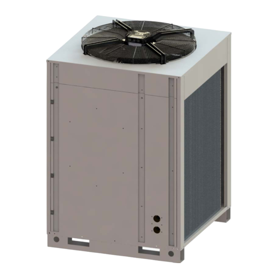
INVERTER AIR/WATER HEAT PUMP CHILLERS WITH AXIAL FANS
This manual has been created for informative purpose. The company declines any responsibility for the results of any projecting or any installation based on the explanations and/or on
the technical specifications provided in this manual. It is besides forbidden the reproduction under any form of the texts and of the figures contained in this manual.
USER'S AND INSTALLER'S MANUALS
Pre‐series
Models
N‐i‐HP 0125
N‐i‐HP 0235
N‐i‐HP 0250
Advertisement
Table of Contents

Subscribe to Our Youtube Channel
Related Manuals for MAXA N-i-HP 0125


Summary of Contents for MAXA N-i-HP 0125
- Page 1 INVERTER AIR/WATER HEAT PUMP CHILLERS WITH AXIAL FANS USER’S AND INSTALLER’S MANUALS Pre‐series Models N‐i‐HP 0125 N‐i‐HP 0235 N‐i‐HP 0250 This manual has been created for informative purpose. The company declines any responsibility for the results of any projecting or any installation based on the explanations and/or on the technical specifications provided in this manual. It is besides forbidden the reproduction under any form of the texts and of the figures contained in this manual. ...
- Page 2 N‐i‐HP Inverter air / water heat pump chillers with axial fans ...
-
Page 3: Table Of Contents
N‐i‐HP Inverter air / water heat pump chillers with axial fans INDEX AIM AND CONTENTS OF THIS MANUAL .......................... 4 KEEP THIS MANUAL .............................. 4 GRAPHIC SYMBOLS ................................ 4 SAFETY LAWS .................................. 4 PERMITTED USES ................................ 4 GENERAL SAFETY GUIDELINES ............................. 5 WORKERS’ HEALTH SAFETY ... - Page 4 N‐i‐HP Inverter air / water heat pump chillers with axial fans 13.2 VERSION ................................... 21 ELECTRIC DATA OF THE UNIT AND AUXILIARIES ...................... 2 2 HEAT PUMPS AVAILABLE HEAD PRESSURE WITH INTEGRATED CIRCULATOR .............. 2 2 15.1 MODEL N‐ ‐HP 0125 ................................ 22 15.2 MODEL N‐ ‐HP 0235 ................................ 22 ...
-
Page 5: Aim And Contents Of This Manual
N‐i‐HP Inverter air / water heat pump chillers with axial fans The N‐i‐HP manual contains all the necessary information for the better use of the appliance under safety conditions for the operator thus meeting the requirements listed in the 2006/42/CE Equipment Directive and following amendments. 1 AIM AND CONTENTS OF THIS MANUAL This manual provides the basic information as for the selection, installation, operation and maintenance of the N‐i‐HP units. It is addressed to the users of the appliance and it enables them to use the unit efficiently, even without any previous specific knowledge of it. ... -
Page 6: General Safety Guidelines
N‐i‐HP Inverter air / water heat pump chillers with axial fans 4 GENERAL SAFETY GUIDELINES Before beginning to operate on N‐i‐HP units every user has to be perfectly knowledgeable about the functions of the equipment and its controls and has to have read and understood the information listed in this manual. It’s strictly forbidden to remove and/or tamper with any safety device. Children or unassisted disabled persons are not allowed to use the appliance. Do not touch the appliance when barefoot or parts of the body are wet or damp. Do not pull, remove or twist the electrical cables coming out from the unit, even if it is disconnected from the main power supply. Do not step with your feet on the appliance, sit down and/or place any type of object. Do not spray or pour water directly on the unit. Do not dispose of, abandon or leave within reach of children packaging materials (cardboard, staples, plastic bags, etc) as they may represent a hazard. Any routine or not‐routine maintenance operation shall be carried out when the equipment has been shut down, disconnected from electric power sources. Do not put neither your hands nor insert screwdrivers, spanners or other tools into moving parts of the equipment. The equipment supervisor and the maintenance man has to receive suitable training for the performance of their tasks in safety. ... -
Page 7: Refrigerant Safety Data Sheet
N‐i‐HP Inverter air / water heat pump chillers with axial fans 4.4 REFRIGERANT SAFETY DATA SHEET Name: R410A (50% Difluoromethane (R32); 50% Pentafluoroethane (R125). RISKS INDICATIONS Major risks: Asphyxia Specific risks: The rapid evaporation may cause freezing. FIRST AID General informations: Never give anything by mouth to an unconscious person. Inhalation: Move to fresh air. Oxygen or artificial respiration if necessary. Do not administer adrenaline or similar drugs. Eyes contact: Rinse carefully with water for at least 15 minutes and consult a doctor. Contact with skin: Wash immediately with plenty of water. Take off immediately the contaminated clothing. FIRE PREVENTION Extinguishing Media: Whatever. Specific risks: Increase in pressure. Specific methods: Use water spray to cool containers ACCIDENTAL RELEASE ACTIONS Personal precautions: Evacuate personnel to safe areas. Provide adequate ventilation. Use personal protective equipment. ... -
Page 8: Technical Characteristics
N‐i‐HP Inverter air / water heat pump chillers with axial fans 5 TECHNICAL CHARACTERISTICS The N‐i‐HP water chillers and heat pumps series are designed for applications in residential and industrial areas, these units are extremely versatile and can operate in heat pump mode with the ability of hot water generation at a temperature of 55°C for environmental heating and sanitary applications. The DC Brushless Inverter compressor technology, matched with the electronic expansion valve, the pump and the variable speed blower are generally used for optimizing the power consumption and efficient operation of the refrigerating components. 5.1 FRAME All N‐i‐HP units are made up of hot‐galvanised thick sheet metal, painted with polyurethane powder enamels at 180°C to ensure the best resistance against atmospheric agents. The front panel is hinged to the lift side to allow access to the internal components for inspection and maintenance. The screws and the inserts are made up of galvanized steel. ... -
Page 9: Monitoring And Protection Devices
N‐i‐HP Inverter air / water heat pump chillers with axial fans The INVERTER system allows to reduce the plant’s water content to its minimum from the usual value 12‐15 liters/kW to 75 liters for the model N‐i‐HP 0125, 105 liters for the model N‐i‐HP 0235 and 150 liters for the modelN‐i‐HP 0250 in ABSOLUTE. Because of the reduced water content, the N‐i‐HP units can be installed in plants without water tank with advantages of the reduced size of the appliance, the installation spaces, heat losses and installation and maintenance costs of the plant. 5.9 MONITORING AND PROTECTION DEVICES The units are standard equipped with the following control and protection devices: return water temperature sensor installed on the return water pipe line from the plant, operating and antifreeze sensor installed on the outlet water pipe to the plant, high pressure transducer, low pressure transducer, compressor’s inlet and outlet temperature sensors, thermal protection device for fan motors, water side water flow switch to protect the evaporator, high pressure HP flow switch. CAUTION: The INVERTER control system is able to manage minimum water contents in the plant up to a value of 75 liters for the model N‐i‐HP 0125, of 105 liters for the model N‐i‐HP 0235, of 150 liters for the model N‐i‐HP 0250, and of 45 liters for the 15 model. This value makes reference to the liters absolute value and not to any kW of installed power. 5.10 HYDRAULIC CIRCUIT ... -
Page 10: Available Versions, Sizes And Accessories
N‐i‐HP Inverter air / water heat pump chillers with axial fans 6 AVAILABLE VERSIONS, SIZES AND ACCESSORIES The code unit is composed of: no. 7 fixed digits (the first two digits identify the series N‐i‐HP in its eventual customizations) the # symbol as a separator no. 9 variables digits (fields) identify the sizes, versions and factory installed accessories no. 2 fixed digits equal to 0, if are not used XX10514#(CT)(TA)(IV)(CI)(KA)(GI)(FAN)(SIL)(TR)00 FATHER CODE SIZE VERSION FACTORY INSTALLED ACCESSORIES XX10514# CT TA IV CI KA GI FAN SIL TR Heating capacity 0 25 kW Water pipes configuration 1 35 kW ... -
Page 11: Optional Accessories
Filed Variant Description CT 0, 1, 2 Heating capacity rating of the unit. 0 The version of 2 pipes provides only Plant Inlet and Outlet Water. TA 1 Not available. 2 Not available. 0 Without vapour injection. IV 1 The vapour injection allows to increase the efficiency of the compressor especially in the critical conditions (air temp. <7°C or >35°C). The configuration with external pump without management in parallel includes the installation of a piece of pipe in the place of the 0 circulator. N.B.: the external pump is not supplied. The configuration with integrated circulator provides a modulating pump with brushless motor, suitable for the use of chilled water and CI 1 directly managed by the controller on‐board unit. The configuration with external pump with management in parallel requests the installation of an ON/OFF motorized valve instead of the 2 circulating pump, in order to exclude the unit if requested by the management of multi unit parallel. N.B.: the external pump is not supplied. 0 Unit not equipped with anti‐freeze kit. KA The antifreeze kit uses a self‐regulating heating cable wrapped around the basement of the unit near the condensing coil and two in PET 1 heaters placed on the faces of the plate heat exchanger. 0 Unit not equipped with management module for plant GI The additional module implements some useful functions for the plant management, such as sanitary hot water SHW, double setpoint, ... -
Page 12: Installation
N‐i‐HP Inverter air / water heat pump chillers with axial fans 7 INSTALLATION WARNING: All the operation described in next chapters MUST BE DONE BY TRAINED PEOPLE ONLY. Before any operation on the unit, be sure that the electric supply is disconnected. 7.1 GENERALITY When installing or servicing the unit, it is necessary to strictly follow the rules listed in this manual, to conform to all the specifications of the labels on the unit, and to take any possible precautions. Not observing the rules reported on this manual can ... -
Page 13: Hydraulic Connections
Front panel Models B* C N‐i‐HP 0125 1500 500 1000 850 N‐i‐HP 0235 1500 500 1000 850 N‐i‐HP 0250 1500 500 1000 850 * The recommended minimum distance for installation, maintenance and operation. 7.4 HYDRAULIC CONNECTIONS The hydraulic connections have to be installed in accordance with national and local regulations; pipes can be made up of steel, galvanized steel or PVC. Pipes have to be designed depending on the nominal water flow and on the hydraulic pressure drops of the system. All the hydraulic connections must to be insulated with closed‐cell material of adequate thickness. Chillers have to be connected to piping by means of flexible joints. The hydraulic circuit should include the following components: • Hole thermometers for monitoring the hydraulic circuit’s temperature. • Manual gate valves to separate the chiller from the hydraulic circuit. • Y‐shaped metallic filter (to be mounted on the return pipe from the plant) with a metallic mesh not larger than 1mm. • Loading group and discharge valve, where it’s necessary. WARNING: Make sure that, when designing the pipe length and diameter, do not exceed the maximum head loss on the plant side, please see the technical data given in the table of Paragraph 12 (available pressure head). ... -
Page 14: Hydraulic Circuit
N‐i‐HP Inverter air / water heat pump chillers with axial fans 7.4.4 Hydraulic circuit Plate heat exchanger A Water flow switch B Service valve C Inlet pressure gauge D Outlet pressure gauge E Air vent valve F Safety valve G Circulating pump H 7.5 REFRIGERANT DIAGRAMS 7.5.1 Refrigerant diagram of the model N‐i‐HP 0125 COMPRESSOR COMPRESSOR INLET TEMPERATURE COMPRESSOR OUTLET TEMPERATURE HIGH PRESSURE TRANSDUCER HIGH PRESSURE FLOW SWITCH LOW PRESSURE TRANSDUCER... -
Page 15: Refrigerant Diagram Of The Model N-I-Hp 0235-0250
7.5.2 Refrigerant diagram of the model N‐i‐HP 0235‐0250 COMPRESSOR COMPRESSOR INLET TEMPERATURE COMPRESSOR OUTLET TEMPERATURE HIGH PRESSURE TRANSDUCER HIGH PRESSURE FLOW SWITCH LOW PRESSURE TRANSDUCER LIQUID SEPARATOR CYCLE REVERSING VALVE LIQUID RECEIVER ELECTRONIC EXPANSION VALVE FILTER AXIAL FAN OUTDOOR AIR TEMPERATURE CIRCULATOR ON BOARD UNIT WATER INLET TEMPERATURE OUT WATER OUTLET TEMPERATURE CP CAPILLARY NRV NO RETURN VALVE PV PRESSURE CHECK VALVE 7.5.3 Refrigerant diagram of the model N‐i‐HP‐LT 0125 COMPRESSOR COMPRESSOR INLET TEMPERATURE COMPRESSOR OUTLET TEMPERATURE HIGH PRESSURE TRANSDUCER HIGH PRESSURE FLOW SWITCH LOW PRESSURE TRANSDUCER LIQUID SEPARATOR CYCLE REVERSING VALVE LIQUID RECEIVER ELECTRONIC EXPANSION VALVE FILTER ... -
Page 16: Refrigerant Diagram Of The Model N-I-Hp-Lt 0235-0250
N‐i‐HP Inverter air / water heat pump chillers with axial fans 7.5.4 Refrigerant diagram of the model N‐i‐HP‐LT 0235‐0250 COMPRESSOR COMPRESSOR INLET TEMPERATURE COMPRESSOR OUTLET TEMPERATURE HIGH PRESSURE TRANSDUCER HIGH PRESSURE FLOW SWITCH LOW PRESSURE TRANSDUCER LIQUID SEPARATOR CYCLE REVERSING VALVE LIQUID RECEIVER ELECTRONIC EXPANSION VALVE FILTER AXIAL FAN OUTDOOR AIR TEMPERATURE CIRCULATOR ON BOARD UNIT WATER INLET TEMPERATURE OUT WATER OUTLET TEMPERATURE NRV NO RETURN VALVE INJ INJECTION VALVE V ON/OFF VALVE WITH SOLENOID PV PRESSURE CHECK VALVE INJT INJECTION TEMPERATURE INJP INJECTION PRESSURE TRANSDUCER 7.6 ELECTRICAL CONNECTIONS Check if the power supply circuit meets the unit’s electric nominal data (tension, phases, frequency) reported on the label sticked ... -
Page 17: Wiring Terminal Block
7.6.1 Wiring terminal block Electrical wiring have to be done only by qualified personnel. The electrical connections have to be realized by qualified personnel. The power supply of the appliances is 3‐Ph/N/PE 400V, 50Hz. The power cables should be brought inside the electrical panel of the unit and connected to the disconneting switch inside the electric panel itself, in the bottom at the left, as shown in the following figure: I ON Do the connections of the power supply cables to the disconneting switch in order from left to right as: protective earth (PE), conductor L1 for phase 1, conductor L2 for phase 2, conductor L3 for phase 3, conductor N for neutral line. The user terminal block (UTB) is located inside the electrical panel. The terminal must be connected according the notes indicated below (the drawing is indicative only). AI10- ADI2 AI10+ GNDR ADI2... - Page 18 N‐i‐HP Inverter air / water heat pump chillers with axial fans DI3 Digital input DI3 Summer/winter input from remote call (close=summer mode / open=winter mode) DI3 Digital input DI3 Summer/winter input from remote call (close=summer mode / open=winter mode) DO1N Digital output, neutral 230 Connections made in factory (see wiring diagrams) Vac DO1 Digital output, phase 230 Vac Connections made in factory (see wiring diagrams) DO2N Digital output, neutral 230 Connections made in factory (see wiring diagrams) Vac DO2 Digital output, phase 230 Vac Connections made in factory (see wiring diagrams) DO3N Digital output, neutral 230 Connections made in factory (see wiring diagrams) Vac DO3 Digital output, phase 230 Vac ...
-
Page 19: Start Up
The following are present the standard connections. Other connections and configurations are shown in the manual control (the permissible configurations tables for user and installer). TERMINAL TYPE CONNECTION AI1E Analogue input NTC ST3E Terminal input for remote plant temperature probe (optional) AI1E Analogue input NTC ST3E Terminal input for remote plant temperature probe (optional) AID1E Digital input DI6E expansion Input terminal for double set‐point consent (only if Hi‐T not presents) board AID1E Digital input DI6E expansion Input terminal for double set‐point consent (only if Hi‐T not presents) board DO1EN Digital output 230 Vac (DO1E) Neutral terminal (230V, 50Hz, 5A resistive, 1 A inductive) for power on the expansion board contactor coil of sanitary integrative heater (not supplied) DO1E Digital output 230 Vac (DO1E) Neutral terminal (230V, 50Hz, 5A resistive, 1 A inductive) for power on the expansion board contactor coil of sanitary integrative heater (not supplied) DO2EN Digital output 230 Vac (DO2E) Neutral terminal (230V, 50Hz, 5A resistive, 1 A inductive) for power on the expansion board contactor coil of sanitary integrative heater (not supplied) ... -
Page 20: Power-On Of The Unit
N‐i‐HP Inverter air / water heat pump chillers with axial fans compressors once the unit is switched on. WARNING: Do not modify the internal wiring of the unit otherwise the warranty will terminate immediately. WARNING: The summer/winter operating mode have to be selected at the beginning of the related season. Frequent and sudden changes of this seasonal operating mode have to be avoided in order to prevent severe damages to compressors. WARNING: When you first install and start‐up the unit make sure that the unit is working properly in both cooling and heating modes. 9 POWER‐ON OF THE UNIT For powering on the machine, rotate the outer handle of the disconnector to the ON position (indicated with "I"). The display on the machine is turned on only if the phase sequence is correct (verification to be done during initial startup). Between a shutdown and subsequent power on, wait a minimum time of 1 minute. 10 SHUTDOWNS FOR LONG PERIODS • Turn off the unit by placing the switch of each unit to "OFF" position. • Close the water valves. • Place the general differential circuit breaker to "OFF" position. If ... -
Page 21: When The Unit Goes Out Of Service
operating life. Refrigerant R410A is mentioned among controlled substances and for this reason it has to be subjected to the mentioned norms. A particular care is recommended during service operations in order to reduce as much as possible any refrigerant loss. ... -
Page 22: Lt Version
N‐i‐HP Inverter air / water heat pump chillers with axial fans WARNING: The minimum temperature allowed for storing the unit is 5°C. 13.2 LT VERSION Models N‐i‐HP‐LT 0125 0235 0250 TECHNICAL CHARACTERISTICS Unit 0125 Circulator 0235 Circulator 0250 Circulator integrated integrated integrated Power supply 400V/3P+N+T/50Hz 400V/3P+N+T/50Hz 400V/3P+N+T/50Hz Maximum power input kW 13,77 14,08 21,54 21,85 25,44 25,91 Electric data Maximum starting current A ... -
Page 23: Electric Data Of The Unit And Auxiliaries
14 ELECTRIC DATA OF THE UNIT AND AUXILIARIES Power supply of the unit V/~/Hz 400/3/50 Remote control circuit V/~/Hz 12/1/50 Control board circuit V/~/Hz 12/1/50 Fans power supply V/~/Hz 230/1/50 Note: Electric data may change for updating. It is therefore necessary to refer always to the technical data label sticked on right‐ side panel of the unit. 15 HEAT PUMPS AVAILABLE HEAD PRESSURE WITH INTEGRATED CIRCULATOR Below the characteristic curves corresponding to Head pressure ‐Water flow without head losses of the hydronic kit at the maximum speed of the circulator. The optimal operating point is shown on each curve under the specified conditions at the apex (4) p. 20. The circuit’s plant must be designed so as to ensure the nominal water flow rate corresponding to the operating points indicated ... -
Page 24: Model N- I -Hp 0250
N‐i‐HP Inverter air / water heat pump chillers with axial fans 15.3 MODEL N‐i‐HP 0250 16 WATER PUMP CURVES 16.1 MODELS N‐i‐HP 0125 – 0235 External control via PWM1 signal 23 ... -
Page 25: Model N- I -Hp 0250
16.2 MODEL N‐i‐HP 0250 External control via 0‐10 V analog signal 17 LOAD LOSSES CURVES OF THE HYDRONIC CIRCUIT We obtain the pressure head of the circulating pump from the sum of the head losses of the hydronic circuit and the available head pressure. For example: for the model N‐i‐HP 0125 with nominal water flow 1,2 L/s (4,3 mc/h) we obtain: 32,9 kPa (head loss) + 85,6 kPa (available head pressure)=118,5 kPa (circulator head pressure). ADVANTIX SPA Via Mansoldo Gettuglio – Loc. La Macia Z.A.I – 37040 ARCOLE (Verona) -
Page 26: Characteristic Curve Of The Control Valve For Unit In Parallel
N‐i‐HP Inverter air / water heat pump chillers with axial fans 18 CHARACTERISTIC CURVE OF THE CONTROL VALVE FOR UNIT IN PARALLEL If the hydronic configuration (CI) is installed on the unit with the variant "shut off valve" (2), the head losses of the ON / OFF motorized valve should be added to those given in the curves of Paragraph 17. For example: for the model N‐i‐HP 0125 with nominal water flow 1,2 L/s (4,3 mc/h) it’s obtained: 2,0 kPa (valve head loss) + 32,9 kPa (hydronic circuit head loss)=34,9 kPa (total internal head loss). 19 ACCESSORIES TO REDUCE THE NOISE LEVEL 19.1 SL ... -
Page 27: Operating Limits
20 OPERATING LIMITS 20.1 EVAPORATOR WATER FLOW RATE The nominal water flow rate is referred to a ∆T equal to 5°C, between the evaporator’s inlet and outlet temperatures. The allowed maximum flow rate is corresponding to ∆T=3°C. Higher values may produce too high pressure drops. The allowed minimum water flow rate is corresponding to ∆T=8°C. Insufficient values may produce too low evaporating temperatures with the intervention of safety devices which would stop the unit and, in some particular cases, the water can freeze in the evaporator coil which can breakdown the refrigeration circuit. We enclosed below a most accurate table showing the minimum flow rates that to ensure for the plate heat exchanger for a the proper operation of unit according to the model (note: the water flow switch is used for preventing the freezing sensor from failure in the case of insufficient water flow but it does not ensure the minimum flow rate required in order the unit can work ... -
Page 28: Correction Factors For Use Of Glycol
N‐i‐HP Inverter air / water heat pump chillers with axial fans Below the operation limits graphed, in the case of air conditioning and sanitary hot water production. 21 CORRECTION FACTORS FOR USE OF GLYCOL Glycol rate Freezing point (°C) CCF IPCF WFCF PDCF 10% ‐3,2 0,985 1,02 1,08 20% ‐7,8 0,98 0,99 1,05 1,12 30% ‐14,1 0,97 0,98 1,10 1,22 40% ‐22,3 0,965 0,97 1,14 1,25 50% ... -
Page 29: Dimensions
22 DIMENSIONS 22.1 MODELS N‐I‐HWAK/WP V2/V2+ 06 IN/OUT: 2”F By inserting the optional element AxiTop the maximum height changes from 1741 mm to 1906 mm. The maximum dimensions of the packaged unit with pallet are: height 2056 mm, while the plant is 1210*1210 mm. ADVANTIX SPA Via Mansoldo Gettuglio – Loc. La Macia Z.A.I – 37040 ARCOLE (Verona) -
Page 30: Internal Views
N‐i‐HP Inverter air / water heat pump chillers with axial fans 23 INTERNAL VIEWS N.B. The number of components indicated can vary depending on the model The representation of the units is indicative and useful to present the main components and can therefore vary From it’s available. The front panel is open at an angle of 90°, electric box closed Panel lock rod Sinks driver boards ... - Page 31 The electric box is open at the first livel Slave controller (mounted only on the versions Master controller Support boards Driver boards with injection and/or with plant management optional module) User terminal block Transformer Trunking cables ...
- Page 32 N‐i‐HP Inverter air / water heat pump chillers with axial fans Internal views of the model N‐i‐HP 0125 with integrated circulator (in the models N‐i‐HP 0235 and 0250 with two compressors) 4‐way valve Electronic expansion valve Compressor Liquid receiver Gas/water plate heat exchanger Liquid separator Circulator ...
-
Page 33: Wiring Diagrams
24 WIRING DIAGRAMS 24.1 MODEL N‐i‐HP 0125 (power supply) ADVANTIX SPA Via Mansoldo Gettuglio – Loc. La Macia Z.A.I – 37040 ARCOLE (Verona) -
Page 34: Model N- I -Hp 0125 ( Control Signals 1)
N‐i‐HP Inverter air / water heat pump chillers with axial fans 24.2 MODEL N‐i‐HP 0125 (control signals 1) 33 ... -
Page 35: Model N- I -Hp 0125 ( Control Signals 2)
24.3 MODEL N‐i‐HP 0125 (control signals 2) ADVANTIX SPA Via Mansoldo Gettuglio – Loc. La Macia Z.A.I – 37040 ARCOLE (Verona) -
Page 36: Model N- I -Hp 0125 (Gi Optional Module Control Signals )
N‐i‐HP Inverter air / water heat pump chillers with axial fans 24.4 MODEL N‐i‐HP 0125 (GI optional module control signals) 35 ... -
Page 37: Model N-I-Hp-Lt 0125 (Power Supply)
24.5 MODEL N‐i‐HP‐LT 0125 (power supply) ADVANTIX SPA Via Mansoldo Gettuglio – Loc. La Macia Z.A.I – 37040 ARCOLE (Verona) -
Page 38: Model N- I -Hp-Lt 0125 ( Control Signals 1)
N‐i‐HP Inverter air / water heat pump chillers with axial fans 24.6 MODEL N‐i‐HP‐LT 0125 (control signals 1) 37 ... -
Page 39: Model N- I -Hp-Lt 0125 ( Control Signals 2)
24.7 MODEL N‐i‐HP‐LT 0125 (control signals 2) ADVANTIX SPA Via Mansoldo Gettuglio – Loc. La Macia Z.A.I – 37040 ARCOLE (Verona) -
Page 40: Model N-I-Hp-Lt 0125 (Injection Control Signals)
N‐i‐HP Inverter air / water heat pump chillers with axial fans 24.8 MODEL N‐i‐HP‐LT 0125 (injection control signals) 39 ... -
Page 41: Model N- I -Hp-Lt 0125 (Gi Module Control Signals )
24.9 MODEL N‐i‐HP‐LT 0125 (GI module control signals) ADVANTIX SPA Via Mansoldo Gettuglio – Loc. La Macia Z.A.I – 37040 ARCOLE (Verona) -
Page 42: Model N-I-Hp 0235-0250 (Power Supply)
N‐i‐HP Inverter air / water heat pump chillers with axial fans 24.10 MODEL N‐i‐HP 0235‐0250 (power supply) 41 ... -
Page 43: Model N- I -Hp 0235-0250 ( Control Signals 1)
24.11 MODEL N‐i‐HP 0235‐0250 (control signals 1) ADVANTIX SPA Via Mansoldo Gettuglio – Loc. La Macia Z.A.I – 37040 ARCOLE (Verona) -
Page 44: Model N- I -Hp 0235-0250 ( Control Signals 2)
N‐i‐HP Inverter air / water heat pump chillers with axial fans 24.12 MODEL N‐i‐HP 0235‐0250 (control signals 2) 43 ... -
Page 45: Model N- I -Hp 0235-0250 (Gi Optional Module Control Signals )
24.13 MODEL N‐i‐HP 0235‐0250 (GI optional module control signals) ADVANTIX SPA Via Mansoldo Gettuglio – Loc. La Macia Z.A.I – 37040 ARCOLE (Verona) -
Page 46: Model N-I-Hp-Lt 0235-0250 (Power Supply)
N‐i‐HP Inverter air / water heat pump chillers with axial fans 24.14 MODEL N‐i‐HP‐LT 0235‐0250 (power supply) 45 ... -
Page 47: Model N- I -Hp-Lt 0235-0250 ( Control Signals 1)
24.15 MODEL N‐i‐HP‐LT 0235‐0250 (control signals 1) ADVANTIX SPA Via Mansoldo Gettuglio – Loc. La Macia Z.A.I – 37040 ARCOLE (Verona) -
Page 48: Model N- I -Hp-Lt 0235-0250 ( Control Signals 2)
N‐i‐HP Inverter air / water heat pump chillers with axial fans 24.16 MODEL N‐i‐HP‐LT 0235‐0250 (control signals 2) 47 ... -
Page 49: Model N-I-Hp-Lt 0235-0250 (Injection Control Signals)
24.17 MODEL N‐i‐HP‐LT 0235‐0250 (injection control signals) ADVANTIX SPA Via Mansoldo Gettuglio – Loc. La Macia Z.A.I – 37040 ARCOLE (Verona) -
Page 50: Model N- I -Hp-Lt 0235-0250 (Gi Module Control Signals )
N‐i‐HP Inverter air / water heat pump chillers with axial fans 24.18 MODEL N‐i‐HP‐LT 0235‐0250 (GI module control signals) 49 ... -
Page 51: Hi-T Remote Touch-Screen Control Panel (Optiona Accessory)
25 Hi‐T REMOTE TOUCH‐SCREEN CONTROL PANEL (OPTIONA ACCESSORY) The Hi‐T is a touch screen remote control for centralized management of a chiller/heat pump and HNS system RS485 newtork. It can also be used for partial functions (ex. as a remote control panel for a single chiller/heat pump or for environment thermostat for manage some fan coils). The network can consist of a maximum of 7 chillers in cascade and a maximum of 70 fan coil divided into 9 therminal zone. It integrates humidity and temperature sensors for the environment thermohygrometer analysis and manage the double setpoint for the radiant floor panel that use a dehumidification system. The intuitive interface simplifies the use of the control, all the functions are easily set through the use of synoptic. For more informations, please see the manual of the Hi‐T device. 26 CRH REMOTE KEYBOARD (OPTIONAL ACCESSORY) The CRH remote keyboard allows you to set the operating mode of the chiller and fan coils units connected to a RS485 network. The network can consist of up to 5 chillers in cascade and fan coils up to 70 units in 9 heating zones. The keyboard can be fitted onto the E503 built‐in wall boxes. For more informations, please see the manual of the CRH device. ADVANTIX SPA Via Mansoldo Gettuglio – Loc. La Macia Z.A.I – 37040 ARCOLE (Verona) -
Page 52: Hydraulic Diagram Type
N‐i‐HP Inverter air / water heat pump chillers with axial fans 27 HYDRAULIC DIAGRAM TYPE 28 HANDBOOK FOR CONFIGURATIONS OF INSTALLATION If you need more information about the possible configurations, there is a handbook, that is a technical book containing a series of recommended drawings of plants that have been highlighted regarding the installation configuration of our high efficiency heat pumps. The "Handbook" aims also the task of showing the symbiotic potential with some of our items in the catalog. You can contact our office for asking the handbook. 51 ... - Page 53 NOTES ........................................ .......................................... .......................................... .......................................... .......................................... .......................................... .......................................... .......................................... .......................................... .......................................... .......................................... .......................................... .......................................... .......................................... .......................................... .......................................... .......................................... .......................................... .......................................... .......................................... .......................................... .......................................... .......................................... .......................................... .......................................... .......................................... .......................................... .......................................... .......................................... .......................................... .......................................... .......................................... .......................................... .......................................... .......................................... .......................................... .......................................... .......................................... .......................................... ..........................................
- Page 54 N‐i‐HP Inverter air / water heat pump chillers with axial fans .......................................... .......................................... .......................................... .......................................... .......................................... .......................................... .......................................... .......................................... .......................................... .......................................... .......................................... .......................................... .......................................... .......................................... .......................................... .......................................... .......................................... .......................................... .......................................... .......................................... .......................................... .......................................... .......................................... .......................................... .......................................... .......................................... .......................................... .......................................... .......................................... .......................................... .......................................... .......................................... .......................................... .......................................... .......................................... .......................................... ...
- Page 56 Serial number...
Need help?
Do you have a question about the N-i-HP 0125 and is the answer not in the manual?
Questions and answers