Sign In
Upload
Manuals
Brands
MAXA Manuals
Heat Pump
i-HP-LT 0235
MAXA i-HP-LT 0235 Manuals
Manuals and User Guides for MAXA i-HP-LT 0235. We have
2
MAXA i-HP-LT 0235 manuals available for free PDF download: User's And Installer's Manual
MAXA i-HP-LT 0235 User's And Installer's Manual (56 pages)
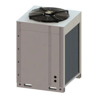
INVERTER AIR/WATER HEAT PUMP CHILLERS WITH AXIAL FANS
Brand:
MAXA
| Category:
Chiller
| Size: 2 MB
Table of Contents
Table of Contents
3
1 Aim and Contents of this Manual
5
How to Keep this Manual
5
Graphic Symbols
5
2 Safety Laws
5
3 Permitted Uses
5
4 General Safety Guidelines
6
Workers' Health and Safety
6
Personal Safety Equipments
6
Safety Symbols
6
Refrigerant Safety Data Sheet
7
5 Technical Characteristics
8
Frame
8
Refrigerant Circuit
8
Compressors
8
Air-Side Exchangers
8
Fan Motor
8
User-Side Heat Exchangers
8
Electrical Control Panel Board
8
Control System
8
Monitoring and Protection Devices
9
Hydraulic Circuit
9
Fan Speed Control
9
Enhanced Vapour Injection (Evi) Tecnology
9
6 Available Versions, Sizes and Accessories
10
Optional Accessories
11
7 Installation
12
Generality
12
Lifting and Handling
12
Location and Minimum Technical Clearances
12
Hydraulic Connections
13
Drainage Connection
13
Service Valve
13
Plant Drainage System
13
Hydraulic Circuit
14
Refrigerant Diagrams
14
Refrigerant Diagram of the Model N-I-HP 0125
14
Refrigerant Diagram of the Model N-I-HP 0235-0250
15
Refrigerant Diagram of the Model N-I-HP-LT 0125
15
Refrigerant Diagram of the Model N-I-HP-LT 0235-0250
16
Electrical Connections
16
Wiring Terminal Block
17
8 Start up
19
9 Power-On of the Unit
20
10 Shutdowns for Long Periods
20
11 Maintenance and Periodical Controls
20
Environmental Protection
20
12 When the Unit Goes out of Service
21
13 Technical Data (Preliminaries)
21
Standard Version
21
Lt Version
22
14 Electric Data of the Unit and Auxiliaries
23
15 Heat Pumps Available Head Pressure with Integrated Circulator
23
Model N- I -Hp 0125
23
Model N- I -Hp 0235
23
Model N- I -Hp 0250
24
16 Water Pump Curves
24
Models N- I -Hp 0125 - 0235
24
Model N- I -Hp 0250
25
17 Load Losses Curves of the Hydronic Circuit
25
18 Characteristic Curve of the Control Valve for Unit in Parallel
26
19 Accessories to Reduce the Noise Level
26
Ssl
26
20 Operating Limits
27
Evaporator Water Flow Rate
27
Cold Water Temperature (Summer Operation)
27
Hot Water Temperature (Winter Operation)
27
Ambient Air Temperature
27
21 Correction Factors for Use of Glycol
28
22 Dimensions
29
Models N-I-Hwak/Wp V2/V2+ 06
29
By Inserting the Optional Element Axitop the Maximum Height Changes from 1741 MM to 1906
29
23 Internal Views
30
24 Wiring Diagrams
33
MODEL N-I-HP 0125 (Power Supply)
33
Model N- I -Hp 0125 ( Control Signals 1)
34
Model N- I -Hp 0125 ( Control Signals 2)
35
Model N- I -Hp 0125 (Gi Optional Module Control Signals )
36
MODEL N-I-HP-LT 0125 (Power Supply)
37
Model N- I -Hp-Lt 0125 ( Control Signals 1)
38
Model N- I -Hp-Lt 0125 ( Control Signals 2)
39
MODEL N-I-HP-LT 0125 (Injection Control Signals)
40
Model N- I -Hp-Lt 0125 (Gi Module Control Signals )
41
MODEL N-I-HP 0235-0250 (Power Supply)
42
Model N- I -Hp 0235-0250 ( Control Signals 1)
43
Model N- I -Hp 0235-0250 ( Control Signals 2)
44
Model N- I -Hp 0235-0250 (Gi Optional Module Control Signals )
45
MODEL N-I-HP-LT 0235-0250 (Power Supply)
46
Model N- I -Hp-Lt 0235-0250 ( Control Signals 1)
47
Model N- I -Hp-Lt 0235-0250 ( Control Signals 2)
48
MODEL N-I-HP-LT 0235-0250 (Injection Control Signals)
49
Model N- I -Hp-Lt 0235-0250 (Gi Module Control Signals )
50
25 Hi-T Remote Touch-Screen Control Panel (Optiona Accessory)
51
26 Crh Remote Keyboard (Optional Accessory)
51
27 Hydraulic Diagram Type
52
28 Handbook for Configurations of Installation
52
Advertisement
MAXA i-HP-LT 0235 User's And Installer's Manual (40 pages)
INVERTER AIR/WATER INDUSTRIAL HEAT PUMPS WITH AXIAL FANS
Brand:
MAXA
| Category:
Heat Pump
| Size: 3 MB
Table of Contents
Table of Contents
4
Purposes and Contents of the Manual
6
Conservation of the Manual
6
Graphic Symbols
6
Safety Laws
6
Permitted Uses
6
General Safety Guidelines
7
Workers' Health and Safety
7
Personal Safety Equipments
7
Safety Symbols
7
Refrigerant Safety Data Sheet
8
Technical Characteristics
9
Frame
9
Refrigerant Circuit
9
Compressors
9
Air-Side Exchanger
9
Fan Motor
9
User-Side Heat Exchanger
9
Electrical Control Panel
9
Control System
9
Monitoring and Protection Devices
9
Hydraulic Circuit
10
Fan Speed Control
10
Enhanced Vapour Injection (Evi) Tecnology
10
Available Versions with Sizes and Accessories
11
Optional Accessories
13
Installation
14
Generality
14
Lifting and Handling
15
Location and Minimum Technical Clearances
15
Hydraulic Connections
15
Hydraulic Circuit
16
Drainage Connection
16
Plant Circuit Loading
16
Plant Drainage System
16
Refrigerant Diagrams
17
Refrigerant Diagram of the Model I-HP 0125 and I-HP 0135
17
Refrigerant Diagram of the Model I-HP 0250F
17
Refrigerant Diagram of the Model I-HP 0250, I-HP 0260 E I-HP 0270
18
Refrigerant Diagram of the Model I-HP-LT 0125
18
Refrigerant Diagram of the Model I-HP-LT 0235
19
Refrigerant Diagram I-HP-LT -0250
19
Electrical Connections
19
Power Supply Terminal Block
20
User's Terminal Block
21
PM Module Phase Protection
21
Plant Management Optional Module Terminal Block
21
Start up
22
Power-On of the Unit
22
Indications for the User
22
Shutdowns for Long Periods
22
Maintenance and Periodical Controls
23
Environmental Protection
23
Disposal of the Unit
23
Technical Data
24
Standard Version
24
Version
26
A-Weighted Sound Power
27
Electric Data of the Unit and Auxiliaries
27
Available Head Pressure of the Unit with Integrated Circulator
27
Circulator's Curves
28
MODELS I-HP 0125 - 0135
28
MODEL I-HP 0250 - 025F
28
MODEL I-HP 0260
29
MOD. I-HP 0260 E I-HP 0270
29
Circulator Characteristics
29
Head Loss Curves of the Hydronic Circuit
29
Characteristic Curve of the Control Valve for Unit in Parallel
30
Accessories to Reduce the Noise Level
30
Ssl
31
Operating Limits
31
Evaporator Water Flow Rate
31
Cold Water Temperature (Summer Operation)
31
Hot Water Temperature (Winter Operation)
31
Ambient Air Temperature
32
Correction Factors for Use of Glycol
33
Dimensions
33
Electric Panel
34
Wiring Diagrams
36
Hydraulic Diagram Type
37
Control Logics
37
Handbook for Configurations of Installation
37
Advertisement
Related Products
MAXA i-HP-LT 0125
MAXA i-HP-LT 0250
MAXA I-HP0125
MAXA i-HP 0235
MAXA i-HP 0250
MAXA i-HP Series
MAXA i-HP 0135
MAXA i-HP 0260
MAXA i-HP 0270
MAXA i-32V5
MAXA Categories
Air Conditioner
Inverter
Chiller
Heat Pump
Heating System
More MAXA Manuals
Login
Sign In
OR
Sign in with Facebook
Sign in with Google
Upload manual
Upload from disk
Upload from URL