Advertisement
Quick Links
4-546-775-01 (1)
アダプターキット
XLR
XLR Adaptor Kit
Kit adaptateur XLR
XLR 适配器套装
取扱説明書
/ Operating Instructions /
Mode d'emploi / Manual de
instrucciones /
5
5
XLR-K2M
安全のために
ソニー製品は安全に充分配慮して設計されています。しかし、 ま
ちがった使いかたをすると、 火災などにより人身事故になること
© 2014 Sony Corporation Printed in Japan
があり危険です。事故を防ぐために次のことを必ずお守りくださ
い。
ˎ 安全のための注意事項を守る
この 「安全のために」 の注意事項をよくお読みください。
ˎ 故障したら使わない
動作がおかしくなったり、 コードなどが破損しているのに気づ
いたら、 すぐにソニーの相談窓口へ相談する。
ˎ 万一、 異常が起きたら
変な音やにおい、
煙が出た場合は
電気製品は安全のための注意事項を守らない
警告表示の意味
と、 火災や人身事故になることがあります。
取扱説明書および製品では、 次のような表示をしています。
この取扱説明書には、 事故を防ぐための重要な注意事項と
表示の内容をよく理解してから本文をお読みください。
製品の取り扱いかたを示しています。
この表示の注意事項を守らないと、 火災・感電
この取扱説明書をよくお読みのうえ、 製品を安全にお使い
ください。お読みになったあとは、 いつでも見られるとこ
などにより死亡や大けがなど人身事故の原因
ろに必ず保管してください。
となります。
この表示の注意事項を守らないと、 感電やその
他の事故によりけがをしたり周辺の家財に損
害を与えたりすることがあります。
注意を促す記号
4
5
6
7
8
9
下記の注意事項を守らないと、
火災・感電
となります。
10
11
12 13
14
製品および同梱物を、 乳幼児の手の届く範囲に放置
しないでください。
乳幼児の手の届かない場所に置き、 口に入れないよう注
1
意する。万一、 飲み込んだ場合は、 ただちに医師に相談
してください。
3
内部に水や異物を入れない
水や異物が入ると火災や感電の原因となります。万一、
2
水や異物が入ったときは、 すぐにスイッチを切り、 ソ
ニーの相談窓口にご相談ください。
下記の注意事項を守らないと、
けが
与えることがあります。
内部を開けない
感電の原因となることがあります。
15
17
内部の点検や修理はソニーの相談窓口へご相談くださ
16
い。
湿気やほこり、 油煙、 湯気の多い場所や直射日光のあ
たる場所には置かない
故障の原因となります。
18
落としたりぶつけたりしない
故障の原因となります。
ブラケット (
VCT-55LH
リーも取り付けた状態で使用する場合、 手持ち撮影
19
をしない
落下等により、 不慮の事故の原因となりますので、 カメ
ラを三脚に取り付けて使用してください。
20
21
主な特長
本機はマルチインターフェースシュー搭載機器対応の
ターとマイクロホンのキットです。
マルチインターフェースシューを搭載していても使用できないカ
メラがあります。
対応機種は
WEB
をご確認ください。
取り扱い上のご注意
ˎ マイクロホンは精密機器です。落としたり、 たたいたり、 強い衝
撃を与えないでください。
ˎ 使用中、 マイクロホンをスピーカーに近づけると "ピー" という
音が発生することがあります (ハウリング現象) 。その場合は、
1
マイクロホンとスピーカーの距離をできるだけ離すか、 スピー
カーの音量を下げてください。
3
ˎ 本機をカメラに取り付けた状態で、 本機をもってカメラを持ち
上げたり、 持ち運んだりしないでください。
ˎ 本機を持ち運ぶ際は、 カメラから取りはずして端子保護キャッ
2 2
プを取り付けて、 同梱のキャリングケースに入れてください。
レンズ交換時のご注意
ˎ レンズ交換は、 本機をカメラから取りはずしてから行ってくだ
さい。
ˎ レンズ交換の際、 レンズおよびカメラボディにウインドスク
リーンの繊維が付着していないか確認してください。付着して
いる場合は、 ブロアーなどで繊維を取り除いてからレンズ交換
してください。
ˎ 本機ご使用後は、 レンズのクリーニングをおすすめします。
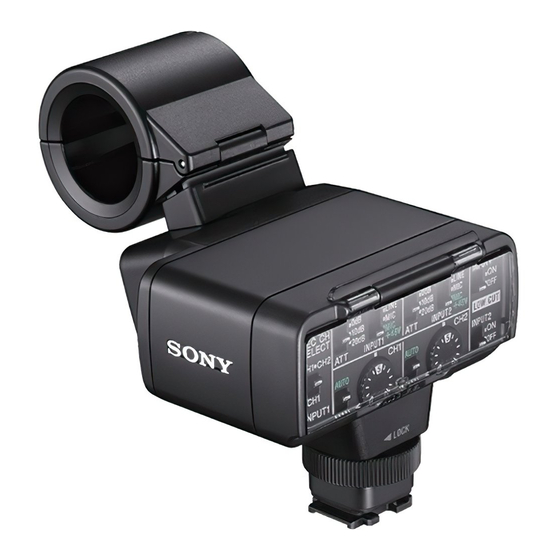
各部の名前
1
3
ウインドスクリーン
1
2
(
4 REC CH SELECT
INPUT1
(
6 INPUT1
LINE/MIC/MIC+48V
7 ATT
(
INPUT2
) スイッチ
(
8 INPUT2
LINE/MIC/MIC+48V
(
) スイッチ
9 LOW CUT
INPUT1
2 2
(
) ダイヤル
11 AUDIO LEVEL
CH1
(
) スイッチ
12 AUTO/MAN
CH2
(
13 AUDIO LEVEL
CH2
14 LOW CUT
(
INPUT2
) スイッチ
マルチインターフェースフット
端子保護キャップ
16
17
リリースレバー
ケーブルホルダー
2
18
19
20 INPUT2
3
21 INPUT1
端子
外部音声の入力:
、
20
21
音源の選択:
6
、
8
1
音源レベルの選択:
、
5
7
録音するチャンネルの選択:
4
録音レベルの選択:
、
、
、
10
11
12
13
風音低減の入
切:
、
/
9
14
アダプターを取り付ける
XLR
端子保護キャップをはずす。
1
XLR
アダプターのマルチインターフェースフット底面から
ロックピンが突き出ていないか確認してください。
アダプターのマルチインターフェースフット
2 XLR
をカメラのマルチインターフェースシューに取り
4
付ける。
アダプターの固定ダイヤルをしっかり締める。
3 XLR
ご注意
アダプターのマルチインターフェースフットを最後まで
ˎ
XLR
しっかり差し込んでから固定ダイヤルを締め、 カメラにしっか
りと固定されていることを確認してください。
アダプターを取りはずすには
XLR
XLR
アダプターの固定ダイヤルを充分にゆるめてから取りはず
す。
マイクを取り付ける
ウインドスクリーン (
) をマイクに取り付ける。
1
-1
マイクホルダーのロックをはずし、 取り付け部のカ
2
バーを開ける。
マイクを型名 (
) が記された部分が上に
3
ECM-XM1
なるようにマイクホルダーの取り付け部に入れ、 カ
バーを閉じ、 マイクホルダーをロックする。
電源を切る
マイクケーブルを
アダプターの
4
XLR
INPUT1
ソニーの相談窓口へ相談する
につなぐ。
接続する機器が
つの場合は、
端子につないでくださ
1
INPUT1
い。
マイクケーブルを
アダプターのケーブルホル
5
XLR
ダー (
) に取り付ける。
-19
ˎ 音声の設定については、 「 音の設定をする」 をご覧ください。
ˎ ケーブルを無理に引っ張ったり、 またはたゆんだ状態でケー
ブルホルダーに取り付けると、 マイクホルダーに取り付けた
マイクが著しく傾く場合があります。
充分な防振効果が得られるように、 マイクが大きく傾かない
ようご注意ください。
行為を禁止する記号
マイクケーブルを取りはずすには
マイクをマイクホルダーから取りはずす。
リリースレバー (
) を下げながら、 プラグを持って引き抜
-18
く。
音の設定をする
大けが
により
の原因
付属マイクを使う
単一指向性のモノラル音声を収録できます。
(
) スイッチを
1 INPUT 1
LINE/MIC/MIC+48V
「
」 に切り換える。
MIC+48V
(
) スイッチを 「
2 REC CH SELECT
INPUT1
」 に切り換える。
CH2
この設定で、 同じ音声が
、
の両方に録音されます。
CH1
CH2
だけに録音したいときは、 「
」 にしてください。
CH1
CH1
録音レベルを調節する
INPUT1
端子
/INPUT2
端子から入力した音声の録音レベルを調節
できます。
内蔵マイクと
入力端子の録音レベルは調節できません。
MIC
調節するチャンネル (
または
1
CH1
CH2
をしたり周辺の家財に
損害
を
スイッチを 「
」 にする。
MAN
MAN
ダイヤルを回して、 適正なレベルに
2 AUDIO LEVEL
なるように音量を調節する。
適正なレベルになっているか、 ヘッドホンやオーディオレベル
メーターで確認してください。
自動調整に戻すには
スイッチを 「
」 にする。
AUTO/MAN
AUTO
風切り音を低減する
端子
端子から入力した音声の風切り音を低減で
INPUT1
/INPUT2
きます。
(
) スイッチまたは
LOW CUT
INPUT1
LOW CUT
(
) スイッチを 「
」 にする。
INPUT2
ON
) 等を介し、 他のアクセサ
外部音声機器などを使う
付属マイク以外のマイクや外部音声機器 (ミキサーなど) を使うに
は、 以下のように設定してください。
入力する音源を選ぶ
1
端子
端子に接続する機器に合わせて、
INPUT1
/INPUT2
INPUT1/INPUT2
(
LINE/MIC/MIC+48V
) スイッチを設定しま
す。
外部音声機器 (ミキサーなど) :
LINE
アダプ
XLR
ダイナミックマイクや電池内蔵のマイク:
MIC
電源 (ファンタム電源) 対応のマイク:
+48V
MIC+48V
ご注意
ˎ
MIC+48V
にしたままで
+48V
電源に対応していない機器を
接続すると、 接続した機器の故障の原因になりますので、 接
続する前にご確認ください。
ˎ 接続しない端子のノイズが気になるときは、
(
) スイッチを 「
INPUT2
LINE/MIC/MIC+48V
ださい。
マイクの入力レベルを設定する。
2
(
) スイッチが 「
INPUT1/INPUT2
LINE/MIC/MIC+48V
「
」 のときは、
(
MIC+48V
ATT
INPUT1/INPUT2
力レベルを設定できます。マイクの感度に応じて調節してく
ださい。
付属のマイクロホン (
) の場合は、
ECM-XM1
ATT 10dB
すめです。
入力レベルは、 以下のようになります。
ATT 0dB
:
-60dBu
:
ATT 10dB
-50dBu
:
ATT 20dB
-40dBu
ご注意
(
) スイッチが
ˎ
INPUT1/INPUT2
LINE/MIC/MIC+48V
ときは、 入力レベルは
に固定されます。
+4dBu
を切り換えても入力レベルは変わりません。
録音するチャンネルを設定する。
3
(
) スイッチで、 録音するチャンネルを
REC CH SELECT
INPUT1
選びます。
REC CH SELECT
(
)
、
に録音される音声
INPUT1
CH1
CH2
マイク
マイクホルダー
スイッチの位置
3
) スイッチ
(
) スイッチ
5 ATT
INPUT1
INPUT1
) スイッチ
・
CH1
CH2
) スイッチ
INPUT1
(
) スイッチ
10 AUTO/MAN
CH1
CH1
INPUT2
(
) プラグが
個ついているステレオマイクを使う
ˎ
XLR
3PIN
2
) ダイヤル
には
INPUT1
端子に
Lch
、
INPUT2
端子に
Rch
15
固定ダイヤル
(
) スイッチを
に設定します。
CH SELECT
INPUT1
CH1
information about recycling of this product, please contact
主な仕様
端子
your local Civic Office, your household waste disposal
service or the shop where you purchased the product.
最大外形寸法 (約) :
< Notice for the customers in the
アダプター (
) 本体
XLR
XLR-A2M
countries applying EU Directives >
116.5 mm
×
105.5 mm
×
75 mm
(幅/高さ/奥行き)
(突起物、 コード含まず)
Manufacturer: Sony Corporation, 1-7-1 Konan Minato-ku
マイクロホン (
)
ECM-XM1
Tokyo, 108-0075 Japan
×
(直径/長さ)
21 mm
162 mm
For EU product compliance: Sony Deutschland GmbH,
(ウインドスクリーン、 コード含まず)
Hedelfinger Strasse 61, 70327 Stuttgart, Germany
質量 (約) :
XLR
アダプター (
XLR-A2M
) 本体
250 g
Features
マイクロホン (
)
ECM-XM1
121.5 g
The XLR-K2M is a kit including an XLR Adaptor for a device
動作温度:
℃ ∼
℃
0
40
equipped with a Multi Interface Shoe and a microphone.
保存温度:
℃ ∼
℃
-20
+60
Some camera models with a Multi Interface Shoe cannot be
入力端子:
used with this kit.
端子:
型
ピン、 凹
INPUT1/INPUT2
XLR
3
For details on compatible camera models of this unit, visit
MIC
:
-60/-50/-40 dBu
、
3 k
Ω
the website of Sony in your area, or consult your dealer of
:
、
Ω
LINE
+4 dBu
10 k
Sony or local authorized Sony service facility.
(
)
0 dBu=0.775 Vrms
同梱物:
Notes on use
アダプター (
) (
) 、 マイクロホン (
) (
) 、
XLR
XLR-A2M
1
ECM-XM1
1
ウインドスクリーン (
1
) 、 端子保護キャップ (
1
) 、 キャリングケー
• The microphone is a precision instrument. Do not drop,
ス (
) 、 印刷物一式
1
仕様および外観は、 改良のため予告なく変更することがあります
• If the microphone is placed near speakers, a howling
が、 ご了承ください。
マルチインターフェースシューはソニー株式会社の商標です。
• Do not hold this unit to pick up or carry the camera when
保証書とアフターサービス
• To carry this unit, remove it from the camera, attach
保証書
ˎ この製品には保証書が添付されていますので、 お買い上げの際
お買い上げ店でお受け取りください。
Notes on changing the lens
ˎ 所定事項の記入および記載内容をお確かめのうえ、 大切に保存
• Before changing the lens, remove this unit from the
してください。
ˎ 保証期間は、 お買い上げ日より
年間です。
1
• Before changing the lens, check whether there are any
アフターサービス
調子が悪いときはまずチェックを
この取扱説明書をもう一度ご覧になってお調べください。
• After using this unit, cleaning the lens is recommended.
それでも具合が悪いときは
端子
ソニーの相談窓口にご相談ください。
保証期間中の修理は
1 Wind screen 2 Microphone 3 Microphone holder
保証書の記載内容に基づいて修理させていただきます。
4 REC CH SELECT (INPUT1) switch 5 ATT (INPUT1) switch
詳しくは保証書をご覧ください。
6 INPUT1 (LINE/MIC/MIC+48V) switch 7 ATT (INPUT2) switch
保証期間経過後の修理は
8 INPUT2 (LINE/MIC/MIC+48V) switch
修理によって機能が維持できる場合は、 ご要望により有償修理さ
9 LOW CUT (INPUT1) switch 10 AUTO/MAN (CH1) switch
せていただきます。
11 AUDIO LEVEL (CH1) dial 12 AUTO/MAN (CH2) switch
部品の保有期間について
13 AUDIO LEVEL (CH2) dial 14 LOW CUT (INPUT2) switch
15 Lock dial 16 Multi Interface foot
当社では本機の補修用性能部品 (製品の機能を維持するために必
17 Connector protect cap 18 Release lever 19 Cable holder
要な部品) を、 製造打ち切り後最低
年間保有しています。この部
7
20 INPUT2 jack 21 INPUT1 jack
品保有期間を修理可能の期間とさせていただきます。ただし、 故
障の状況その他の事情により、 修理に代えて製品交換をする場合
Inputting external sound: 20, 21
がありますのでご了承ください。保有期間が経過したあとも、 故
Selecting a sound source: 6, 8
障箇所によっては修理可能の場合がありますので、 ソニーの相談
Selecting a sound source level: 5, 7
窓口にご相談ください。
Selecting channel setting for recording: 4
ご相談になるときは、 次のことをお知らせください。
Selecting the recording level: 10, 11, 12, 13
ˎ 品名:
XLR-K2M
Switching wind noise reduction to ON/OFF: 9, 14
ˎ 故障の状態:できるだけ詳しく
ˎ 購入年月日
1 Detach the connector protect cap from
2 Attach the Multi Interface foot of the XLR
・
CH1
3 Tighten the lock dial of the XLR Adaptor
Notes
• Insert the Multi Interface foot of the XLR Adaptor fully into
) の
AUTO/
When detaching the XLR Adaptor
Fully loosen the lock dial of the XLR Adaptor before
detaching the XLR Adaptor.
Before operating the product, please read this manual
thoroughly and retain it for future reference.
1 Attach the wind screen (-1) to the
WARNING
2 Unlock the stopper of the microphone
To reduce fire or shock hazard, do not expose the unit to
rain or moisture.
Keep out of reach of small children to prevent accidental
3 Place the microphone into the holder so
swallowing.
For the Customers in the U.S.A.
CAUTION
You are cautioned that any changes or modifications not
4 Connect the connector plug of the
expressly approved in this manual could void your authority
to operate this equipment.
Note:
This equipment has been tested and found to comply
with the limits for a Class B digital device, pursuant to Part
15 of the FCC Rules. These limits are designed to provide
5 Put the microphone cable into the cable
reasonable protection against harmful interference in a
residential installation. This equipment generates, uses,
and can radiate radio frequency energy and, if not installed
and used in accordance with the instructions, may cause
harmful interference to radio communications. However,
there is no guarantee that interference will not occur in a
particular installation. If this equipment does cause harmful
interference to radio or television reception, which can be
INPUT1/
When detaching the microphone cable
determined by turning the equipment off and on, the user
」 にしてく
LINE
is encouraged to try to correct the interference by one or
Detach the microphone from the microphone holder.
more of the following measures:
Unplug the microphone plug while pressing the release
— Reorient or relocate the receiving antenna.
」 か
— Increase the separation between the equipment and
MIC
Audio setup
) スイッチで入
receiver.
— Connect the equipment into an outlet on a circuit different
Using the supplied microphone
from that to which the receiver is connected.
がおす
— Consult the dealer or an experienced radio/TV technician
You can record unidirectional monaural sound with the
for help.
microphone.
1 Set the INPUT1 (LINE/MIC/MIC+48V)
THIS DEVICE COMPLIES WITH PART 15 OF THE FCC
RULES. OPERATION IS SUBJECT TO THE FOLLOWING TWO
CONDITIONS:
2 Set the REC CH SELECT (INPUT1) switch to
(1) THIS DEVICE MAY NOT CAUSE HARMFUL INTERFERENCE,
AND (2) THIS DEVICE MUST ACCEPT ANY INTERFERENCE
の
LINE
RECEIVED, INCLUDING INTERFERENCE THAT MAY CAUSE
スイッチ
ATT
UNDESIRED OPERATION.
Adjusting the recording level
For the Customers in Europe
You can adjust the recording level input from the INPUT1/
Disposal of Old Electrical & Electronic
INPUT2 jacks.
Equipment (Applicable in the European
You cannot adjust the recording level of the internal
Union and other European countries with
microphone and MIC input jack.
separate collection systems)
This symbol on the product or on its
1 Set the AUTO/MAN (CH1/CH2) switch of
packaging indicates that this product
shall not be treated as household waste.
CH1
2 Turn the AUDIO LEVEL dial to adjust the
Instead it shall be handed over to the
CH2
applicable collection point for the recycling of electrical
and electronic equipment. By ensuring this product is
CH1
disposed of correctly, you will help prevent potential
CH2
negative consequences for the environment and human
To restore automatic adjustment
health, which could otherwise be caused by inappropriate
Set the AUTO/MAN (CH1/CH2) switch to AUTO.
を接続し、
REC
waste handling of this product. The recycling of materials
will help to conserve natural resources. For more detailed
Reducing wind noise
You can reduce wind noise input from the INPUT1/INPUT2
jacks.
Set the LOW CUT (INPUT1) switch or LOW
CUT (INPUT2) switch to ON.
Using an external audio device
Set as follows when you use a microphone other than the
supplied microphone or an external audio device (mixer,
etc.).
1 Select the sound source to be input.
Set the INPUT1/INPUT2 (LINE/MIC/MIC+48V) switch
according to the device to be connected to the INPUT1/
INPUT2 jacks.
External audio device (mixer, etc.): LINE
Dynamic microphone or microphone with built-in
battery: MIC
Microphone that is 48V phantom power compliant:
MIC+48V
Notes
• If you connect a device that does not support 48V
phantom power, malfunction may result from setting
knock it, or subject it to excessive shock.
this switch to MIC+48V. Check before connecting the
device.
effect (acoustic feedback) may occur. If this happens,
• If noise from the unused jack bothers you, set the
place the microphone as far as possible from the
INPUT1/INPUT2 (LINE/MIC/MIC+48V) switch of the
speakers, or lower the volume of the speaker.
unused jack to LINE.
2 Set the input level of the microphone.
attached.
When the INPUT1/INPUT2 (LINE/MIC/MIC+48V) switch is
set to MIC or MIC+48V, you can set the input level with
the connector protect cap to this unit and put it in the
the ATT (INPUT1/INPUT2) switch.
supplied carrying case.
Adjust according to the microphone sensitivity.
ATT 10dB is recommended when you use the supplied
microphone (ECM-XM1).
camera.
The input levels are as follows.
ATT 0dB: -60dBu
fibers from the wind screen on the lens or camera body.
ATT 10dB: -50dBu
Brush any fibers off with a blower etc. and then change
ATT 20dB: -40dBu
the lens.
Notes
• When the INPUT1/INPUT2 (LINE/MIC/MIC+48V) switch
is set to LINE, the input level is fixed to +4dBu. Even
Identifying the parts
if you reset the ATT switch, the input level does not
change.
3 Set the channel to be recorded.
You can select the channel to be recorded, with the REC
CH SELECT (INPUT1) switch.
Position of the REC
CH SELECT (INPUT1)
switch
CH1·CH2
CH1
• To use a stereo microphone with two XLR (3PIN) plugs,
connect Lch to the INPUT1 jack and Rch to the INPUT2
jack, and set the REC CH SELECT (INPUT1) switch to
CH1.
Attaching the XLR Adaptor
Specifications
Maximum dimensions (Approx.)
the connector plug of the XLR Adaptor.
XLR Adaptor (XLR-A2M) unit
Check that the lock pin is not protruding from the bottom
116.5 mm × 105.5 mm × 75 mm (w/h/d)
of the Multi Interface foot of the XLR Adaptor.
(4 5/8 in. × 4 1/4 in. × 3 in.)
(excluding the cord and projecting parts)
Microphone (ECM-XM1)
Adaptor to the Multi Interface Shoe of
21 mm × 162 mm (Diameter/Length)
the camera.
(27/32 in. × 6 1/2 in.)
(excluding the wind screen and cord)
Mass (Approx.)
securely.
XLR Adaptor (XLR-A2M) unit 250 g (8 oz)
Microphone (ECM-XM1)
Operating temperature 0 °C to 40 °C (32 °F to 104 °F)
the Multi Interface Shoe of the camera, and tighten the
Storage temperature
lock dial securely. Make sure this unit is attached securely.
Input jacks
INPUT1/INPUT2 jacks: XLR3-pin, female
MIC: -60 dBu /-50 dBu /-40 dBu, 3 kΩ(kilohms)
LINE: +4 dBu, 10 kΩ (kilohms)
(0 dBu=0.775 Vrms)
Included items
Attaching the microphone
XLR Adaptor (XLR-A2M) (1), Microphone (ECM-XM1) (1),
Wind screen (1), Connector protect cap (1), Carrying case
(1), Set of printed documentation
microphone.
Design and specifications are subject to change without
notice.
holder and open the cover.
Multi Interface Shoe is a trademark of Sony Corporation.
that the model name (ECM-XM1) on the
microphone faces upward. Then close the
Avant d'utiliser ce produit, prière de lire attentivement ce
cover and firmly lock the stopper.
mode d'emploi et de le conserver pour toute référence
future.
AVERTISSEMENT
microphone to the INPUT1 jack on the
XLR Adaptor.
Afin de réduire les risques d'incendie ou de décharge
Connect the connector plug of the microphone to the
électrique, n'exposez pas cet appareil à la pluie ou à
INPUT1 jack if you connect one device.
l'humidité.
Rangez hors de portée des enfants pour éviter toute
ingestion accidentelle.
holder (-19) on the XLR Adaptor.
À l'intention des clients aux É.-U.
• See "Audio setup" for audio recording.
• If the cable is pulled with too much force or attached to
AVERTISSEMENT
the cable holder too loosely, the microphone attached
Par la présente, vous êtes avisé du fait que tout
to the microphone holder may tilt a lot.
changement ou toute modification ne faisant pas l'objet
To get the full anti-vibration effect, make sure the
d'une autorisation expresse dans le présent manuel
microphone is not tilting too much.
pourrait annuler votre droit d'utiliser l'appareil.
Note
L'appareil a été testé et est conforme aux exigences d'un
appareil numérique de Classe B, conformément à la Partie
lever (-18) down.
15 de la réglementation de la FCC.
Ces critères sont conçus pour fournir une protection
raisonnable contre les interférences nuisibles dans un
environnement résidentiel. L'appareil génère, utilise et peut
émettre des fréquences radio; s'il n'est pas installé et utilisé
conformément aux instructions, il pourrait provoquer des
interférences nuisibles aux communications radio.
Cependant, il n'est pas possible de garantir que des
interférences ne seront pas provoquées dans certaines
switch to MIC+48V.
conditions particulières. Si l'appareil devait provoquer des
interférences nuisibles à la réception radio ou à la télévision,
CH1·CH2.
ce qui peut être démontré en allumant et éteignant
l'appareil, il est recommandé à l'utilisateur d'essayer de
This setting enables recording on both CH1 and CH2. Set
corriger cette situation par l'une ou l'autre des mesures
the switch to CH1 if you want to record on CH1 only.
suivantes :
— Réorienter ou déplacer l'antenne réceptrice.
— Augmenter la distance entre l'appareil et le récepteur.
— Brancher l'appareil dans une prise ou sur un circuit
différent de celui sur lequel le récepteur est branché.
— Consulter le détaillant ou un technicien expérimenté en
radio/téléviseurs.
the channel to be adjusted to MAN.
Cet appareil est conforme à la section 15 des règlements
FCC. Son fonctionnement est soumis aux deux conditions
volume to the proper level.
suivantes : (1) cet appareil ne doit pas provoquer
d'interférences nuisibles, (2) cet appareil doit accepter toute
Check that the volume is at the proper level, with
interférence, y compris celles susceptibles de provoquer son
headphones or audio level meter.
fonctionnement indésirable.
Pour les clients en Europe
Traitement des appareils électriques et
électroniques en fin de vie (Applicable
dans les pays de l'Union Européenne et
aux autres pays européens disposant de
systèmes de collecte sélective)
Ce symbole, apposé sur le produit ou sur son
emballage, indique que ce produit ne doit
pas être traité avec les déchets ménagers.
Il doit être remis à un point de collecte
approprié pour le recyclage des équipements électriques et
électroniques. En vous assurant que ce produit sont mis au
rebut de façon appropriée, vous participez activement à la
prévention des conséquences négatives que leur mauvais
traitement pourrait provoquer sur l'environnement et sur la
santé humaine. Le recyclage des matériaux contribue par
ailleurs à la préservation des ressources naturelles. Pour
toute information complémentaire au sujet du recyclage de
ce produit, vous pouvez contacter votre municipalité, votre
déchetterie locale ou le point de vente où vous avez acheté
le produit.
< Avis aux consommateurs des pays
appliquant les Directives UE >
Fabricant: Sony Corporation, 1-7-1 Konan Minato-ku Tokyo,
108-0075 Japon
Pour toute question relative à la conformité des produits
dans l'UE: Sony Deutschland GmbH, Hedelfinger Strasse 61,
70327 Stuttgart, Allemagne
Caractéristiques
Le XLR-K2M est un kit comprenant un adaptateur XLR pour
appareil à griffe multi-interface et un microphone.
Certains modèles d'appareils photo/caméscopes à griffe
multi-interface ne peuvent pas être utilisés avec ce kit.
Pour plus de détails sur les modèles d'appareils photo/
caméscopes compatibles avec cet accessoire, consultez le
site Web de Sony de votre région, ou adressez-vous à votre
revendeur Sony ou au service après-vente agréé Sony local.
Remarques sur l'emploi
• Le microphone est un instrument de précision. Ne le
laissez pas tomber, ne le cognez pas et ne le soumettez
pas à des chocs.
• Si le microphone est placé près d'enceintes, un hurlement
(rétroaction acoustique) peut se produire. Dans ce cas,
éloignez le plus possible le microphone des enceintes, ou
bien réduisez le volume du microphone.
• Ne soulevez pas ou ne tenez pas l'appareil photo/
Audio recorded on CH1 & CH2
caméscope par cet accessoire lorsque ce dernier est
rattaché.
INPUT1
CH1
• Pour transporter cet accessoire, retirez-le de l'appareil
CH2
photo/caméscope, rattachez le capuchon de protection
INPUT1
CH1
de connecteur et rangez-le dans l'étui de transport fourni.
INPUT2
CH2
Remarques sur le changement d'objectif
• Avant de changer d'objectif, retirez cet accessoire de
l'appareil photo/caméscope.
• Avant de changer d'objectif, assurez-vous de l'absence de
fibres de la bonnette antivent sur l'objectif ou l'appareil
photo/caméscope. Retirez toute fibre avec un soufflet, etc.
avant de changer d'objectif.
• Il est conseillé de nettoyer l'objectif après l'utilisation de
cet accessoire.
Identification des éléments
1 Bonnette antivent 2 Microphone
3 Support de microphone
4 Commutateur REC CH SELECT (INPUT1)
5 Commutateur ATT (INPUT1)
6 Commutateur INPUT1 (LINE/MIC/MIC+48V)
7 Commutateur ATT (INPUT2)
8 Commutateur INPUT2 (LINE/MIC/MIC+48V)
9 Commutateur LOW CUT (INPUT1)
121.5 g (4 oz)
10 Commutateur AUTO/MAN (CH1)
11 Molette AUDIO LEVEL (CH1)
-20 °C to +60 °C (-4 °F to +140 °F)
12 Commutateur AUTO/MAN (CH2)
13 Molette AUDIO LEVEL (CH2)
14 Commutateur LOW CUT (INPUT2)
15 Molette de verrouillage 16 Sabot multi-interface
17 Capuchon de protection de connecteur
18 Levier de libération 19 Support de câble
20 Prise d'entrée INPUT2 21 Prise d'entrée INPUT1
Transmission d'un son externe: 20, 21
Sélection d'une source sonore: 6, 8
Sélection du niveau d'une source sonore: 5, 7
Sélection d'un canal pour l'enregistrement: 4
Sélection du niveau d'enregistrement: 10, 11, 12, 13
Activation/désactivation de la réduction du bruit du
vent: 9, 14
Fixation de l'adaptateur
XLR
1 Détachez le capuchon de protection de
connecteur de la fiche-connecteur de
l'adaptateur XLR.
Assurez-vous que la goupille de verrouillage ne dépasse
pas de la partie inférieure du sabot multi-interface de
l'adaptateur XLR.
2 Raccordez le sabot multi-interface
de l'adaptateur XLR à la griffe multi-
interface de l'appareil photo/caméscope.
3 Serrez correctement la molette de
verrouillage de l'adaptateur XLR.
Remarques
• Insérez à fond le sabot multi-interface de l'adaptateur
XLR dans la griffe multi-interface de l'appareil photo/
caméscope, puis serrez la molette de verrouillage.
Assurez-vous que cet accessoire est bien rattaché.
Pour détacher l'adaptateur XLR
Desserrez complètement la molette de verrouillage de
l'adaptateur XLR avant de détacher l'adaptateur XLR.
(Suite à la page arrière)
Advertisement

Related Manuals for Sony XLR-K2M


Summary of Contents for Sony XLR-K2M
- Page 1 121.5 g Set the INPUT1/INPUT2 (LINE/MIC/MIC+48V) switch rebut de façon appropriée, vous participez activement à la 端子保護キャップをはずす。 The XLR-K2M is a kit including an XLR Adaptor for a device 動作温度: ℃ ∼ ℃ according to the device to be connected to the INPUT1/ prévention des conséquences négatives que leur mauvais...
- Page 2 LOW CUT (INPUT2) sur el volumen al nivel apropiado. 请用吹风机等将其吹走,然后再更换镜头。 • 如果是未用的插孔发出噪音,请将此插孔 El XLR-K2M es un juego que incluye un adaptador para XLR • 使用本装置后,建议对镜头进行清洁。 Compruebe que el volumen esté al nivel apropiado con para un dispositivo equipado con una zapata de interfaz 的...
Need help?
Do you have a question about the XLR-K2M and is the answer not in the manual?
Questions and answers