Table of Contents
Advertisement
Quick Links
2019/08/08 22:12:05 (GMT+09:00)
SERVICE MANUAL
Ver. 1.0 2019.08
Conditions of Use:
(1)
Please use this information only for the purpose of performing repair, maintenance and/or confi guration services of the Sony products (hereinafter the "Repair services") under the
service agreement entered into with the Sony group company (hereinafter the "Service agreement"). Using this information for any purpose other than the purpose described foregoing
is forbidden.
(2)
Only the Authorized Servicer's offi cers, employees or subcontractors (including their offi cers and employees) whose duties justify a need-to-know and who have agreed to hold
confi dential this information (collectively hereinafter the "Permitted users") are permitted to access and use this information. To disclose or disseminate to any person other than the
Permitted users is forbidden.
(3)
Destroy or erase any and all portion of this information promptly in an irrecoverable and secure fashion after achieving the purpose described in Section (1) above.
(4)
Do not copy, replicate, reproduce, alter, translate, transmit, sell, lease, or distribute this information in whole or in part without the prior written permission of the author.
(Notwithstanding foregoing, it is permitted to copy and distribute this information to the Permitted users.)
(5)
Please notify immediately any leakage, loss, theft, misappropriation, or other misuse of this information by e-mail to the following address:
somk-gcs-tissnexim-adm@jp.sony.com
(6)
In addition to the above, the terms and conditions of the Service agreement shall be applied to using this information.
Revision of Information:
This information may be changed or updated at any time without any prior notice. Please confi rm that this information is up-to-date before using it.
9-896-877-11
2019H33-1
©
2019.08
Sony Imaging Products & Solutions Inc.
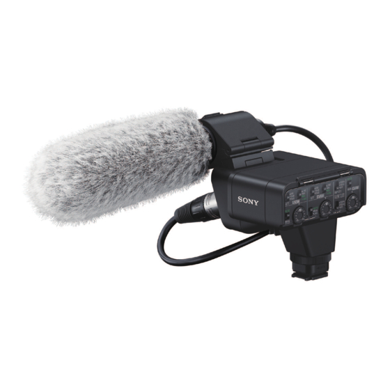
SPECIFICATIONS
p
Dimensions (Approx.):
XLR Adaptor (XLR-A3M) unit
113.2 mm × 106.1 mm × 79 mm (Width/Height/Depth)
(4 1/2 in. × 4 1/4 in. × 3 1/8 in.)
(excluding the cord and projecting parts)
Microphone (ECM-XM1)
21 mm × 162 mm (Diameter/Length)
(27/32 in. × 6 1/2 in.)
(excluding the wind screen and cord)
Mass (Approx.):
XLR Adaptor (XLR-A3M) unit 187 g (6.6 oz)
Microphone (ECM-XM1) 121.5 g (4 oz)
Supplied items:
XLR Adaptor (XLR-A3M) (1), Microphone (ECM-XM1) (1),
Wind screen (1), Connector protect cap (attached) (2),
Extension Cable for Audio (1), Case (1), Set of printed
documentation
Design and specifications are subject to change without notice.
Multi Interface Shoe is a trademark of Sony Corporation.
XLR-K3M
Canadian Model
Chinese Model
XLR ADAPTOR KIT
US Model
AEP Model
UK Model
E Model
SYS SET
Advertisement
Table of Contents

Related Manuals for Sony XLR-K3M


Summary of Contents for Sony XLR-K3M
- Page 1 Conditions of Use: Please use this information only for the purpose of performing repair, maintenance and/or confi guration services of the Sony products (hereinafter the “Repair services”) under the service agreement entered into with the Sony group company (hereinafter the “Service agreement”). Using this information for any purpose other than the purpose described foregoing is forbidden.
-
Page 2: Safety Check-Out
CRITIQUES POUR LA SÉCURITÉ DE FONCTIONNEMENT. NE COMPONENTS WITH SONY PARTS WHOSE PART NUMBERS REMPLACER CES COMPOSANTS QUE PAR DES PIÈCES SONY APPEAR AS SHOWN IN THIS MANUAL OR IN SUPPLEMENTS DONT LES NUMÉROS SONT DONNÉS DANS CE MANUEL OU PUBLISHED BY SONY. -
Page 3: Servicing Notes
2019/08/08 22:12:05 (GMT+09:00) XLR-K3M 1. SERVICING NOTES ABOUT REPAIRING THE BOARD NOTES FOR FLEXIBLE BOARD The mounted parts of this unit that have each board cannot replace Make sure that the conductive side of a fl exible board does not have with single. -
Page 4: Disassembly Flow
2019/08/08 22:12:05 (GMT+09:00) XLR-K3M 2. DISASSEMBLY • Disassembled in the order shown in the fl owchart below. 2-1. DISASSEMBLY FLOW 2-2. CONNECTOR CABINET (Page 5) 2-3. MAIN FRAME BLOCK (Page 6) 2-4. SIDE SW SUB ASSY 2-5. HN-1053 BOARD 2-7. SHOE SUB ASSY... - Page 5 2019/08/08 22:12:05 (GMT+09:00) XLR-K3M Note: Disassemble in the order indicated by the numbers assigned to the parts in the fi gures such as 1. 2-2. CONNECTOR CABINET top side 1 Remove the microphone holder rod of microphone holder (973) assy and open it.
- Page 6 2019/08/08 22:12:05 (GMT+09:00) XLR-K3M 2-3. MAIN FRAME BLOCK bottom side left side USB cover 3 Open the USB cover. 1 XLR cover 2 cable clamper right side 4 Remove the hook of USB cover from the groove. 5 USB cover groove hook Turn over.
- Page 7 2019/08/08 22:12:05 (GMT+09:00) XLR-K3M 2-4. SIDE SW SUB ASSY top side left side 3 Remove the side SW sub assy 5 side SW sub assy in the direction of the arrow. hole 7 center cabinet block hole hole 2 tapping screw groove The opposite side is (T1.7...
- Page 8 2019/08/08 22:12:05 (GMT+09:00) XLR-K3M 2-6. XL-1011 BOARD, FP-2455 FLEXIBLE BOARD top side 1 two screws (M1.7 2.5) 2 shield plate hole Note 1: When installing the shield plate, align the two bosses and two holes. rear side hole boss 5 Pull out the XL-1011 board in the direction of the arrow.
- Page 9 2019/08/08 22:12:05 (GMT+09:00) XLR-K3M 2-7. SHOE SUB ASSY top side left side 1 four tapping screws (M1.7 right side hole 2 Remove the shoe sub assy in the direction of the arrow. 3 Draw out the RY-2001 flexible board from the hole.
- Page 10 2019/08/08 22:12:05 (GMT+09:00) XLR-K3M 2-8. REAR SW SUB ASSY, REAR SW COVER SUB ASSY top side 1 three tapping screws (M1.7 2 Slant the rear SW sub assy in the direction of the arrow, and remove the two bosses from the two holes.
-
Page 11: Exploded Views
2019/08/08 22:12:05 (GMT+09:00) XLR-K3M 3. EXPLODED VIEWS Note: The components identified by mark 0 or dotted line with • -XX and -X mean standardized parts, so they may have some dif- mark are critical for safety. ference from the original one. Replace only with part number specified. - Page 12 2019/08/08 22:12:05 (GMT+09:00) XLR-K3M 3-2. CENTER CABINET SECTION top side left side rear side FFC2 front side right side bottom side Ref. No. Part No. Description Remark Ref. No. Part No. Description Remark 307889021 SCREW, TAPPING (M1.7) (L = 5.0 mm) A5010865A...
- Page 13 2019/08/08 22:12:05 (GMT+09:00) XLR-K3M 3-3. MICROPHONE HOLDER SECTION top side left side not supplied not supplied not supplied right side bottom side Ref. No. Part No. Description Remark Ref. No. Part No. Description Remark X25967332 HOLDER (973) ASSY, MICROPHONE 328462111 CUSHION, MICROPHONE HOLDER...
- Page 14 2019/08/08 22:12:05 (GMT+09:00) XLR-K3M 3-4. FUSE – HN-1053 BOARD (Side A) – – HN-1053 BOARD (Side B) – Ref. No. Part No. Description Remark 0 F1 152340711 FUSE (1A/32V) 0 F2 152340711 FUSE (1A/32V) 0 F3 152340911 FUSE (1.5A/32V) SYS SET...
-
Page 15: Supplied Accessories
2019/08/08 22:12:05 (GMT+09:00) XLR-K3M 4. SUPPLIED ACCESSORIES Note: • Items marked “*” are not stocked since they are seldom required for routine service. Some delay should be anticipated when ordering these items. Ref. No. Part No. Description Remark 500608701 MANUAL, INSTRUCTION (SG) (JAPANESE,... - Page 16 2019/08/08 22:12:05 (GMT+09:00) XLR-K3M Revision History Ver. Date History Contents 2019.08 Official Release — SYS SET...
Need help?
Do you have a question about the XLR-K3M and is the answer not in the manual?
Questions and answers