Table of Contents
Advertisement
Quick Links
Advertisement
Table of Contents

Subscribe to Our Youtube Channel
Related Manuals for Karma EvO Lectus


Summary of Contents for Karma EvO Lectus
- Page 1 user manual...
- Page 2 release: 2015-08-22...
-
Page 3: Table Of Contents
1. index 1. index _______________________________________________________ 3 2. how to contact Karma _________________________________________ 9 3. declaration of conformity ______________________________________ 10 4. introduction _________________________________________________ 11 chassis number _______________________________________________ 11 chassis serial plate _____________________________________________ 11 stands for the chassis serial number. ________________________ 12 5. - Page 4 10.2.6 upholstered armrest __________________________________ 25 10.2.7 legrest _____________________________________________ 25 10.2.8 powered legrest adjustment (optional) ____________________ 25 10.2.9 upholstered headrest (optional) _________________________ 26 10.2.10 upholstered calf support (optional) ______________________ 27 10.2.11 upholstered lateral support (optional) ____________________ 27 10.2.12 upholstered hip support (optional) ______________________ 28 10.2.13 positioning belt (optional) _____________________________ 28 10.3 the controls _____________________________________________ 29 10.3.1 side steering control __________________________________ 29...
- Page 5 11.2.13.2 setting the height position of the hip support _____________ 52 11.2.14 lateral support settings _______________________________ 54 11.3 positioning belts _________________________________________ 55 11.4 control settings __________________________________________ 56 11.4.1 height adjustment side control: _________________________ 56 11.4.2 depth adjustment side control ___________________________ 56 12 control panel _______________________________________________ 57 12.1 charging socket _________________________________________ 57 12.2 joystick ________________________________________________ 57...
- Page 6 12.4.5 mode button ________________________________________ 66 12.4.6 profile button ________________________________________ 66 12.4.7 hazard Warning Button and LED ________________________ 66 12.4.8 lights Button and LED _________________________________ 66 12.4.9 left Indicator Button and LED ___________________________ 67 12.4.10 right Indicator Button and LED _________________________ 67 12.5 jack sockets ____________________________________________ 67 12.5.1 external profile switch jack _____________________________ 67 12.5.2 external on/off switch jack ______________________________ 67...
- Page 7 15.3 stopping the wheelchair ___________________________________ 84 16 using the powered seat functions _______________________________ 84 17 using additional function of the wheelchair menu ___________________ 85 17 handling the mechanical brakes ________________________________ 86 17.1 release the mechanical brakes _____________________________ 86 18 charging the maintenance free batteries __________________________ 87 18.1 battery level ____________________________________________ 87 18.2 charging socket _________________________________________ 88 18.3 disposal of broken or worn out batteries ______________________ 90...
- Page 8 22 disposal of the product ______________________________________ 106 23 trouble shooting ____________________________________________ 107 23.1 diagnostics R-Net LCD ___________________________________ 108 24 technical specifications ______________________________________ 109 25 accessories _______________________________________________ 111...
-
Page 9: How To Contact Karma
European office for sales and service: Karma Europe BV Euregiopark 12 6467 JE Kerkrade Netherlands phone: +31 (0)45 820 01 50 facsimile: +31 (0)45 820 01 59 mail: info@karma-europe.com web: www.karma-europe.com Produced and published by Karma Medical, Taiwan Technical changes and print errors prohibited. -
Page 10: Declaration Of Conformity
3. declaration of conformity... -
Page 11: Introduction
Karma runs the policy of continuously product improvement. Therefore pictures of products or options as shown in this manual might be different from what you see in this manual. Karma reserves the right to make changes to the product without prior notice. -
Page 12: Sn: Stands For The Chassis Serial Number
The used symbols on the chassis plate are explained below: describes the model and type of the product. stands for indoor- and outdoor use (Class B). stands for the date of production. this icon stands for the maximum driving speed. this icons stands for the maximum slope to drive on. -
Page 13: Used Symbols For Warning, Caution And Note
5. used symbols for warning, caution and note General warnings are indicated by a symbol. There are three levels of warnings: 1. warning If you see this sign please use extreme caution where this symbol appears. Neglecting these warnings can lead to personal or material damage. -
Page 14: Warranty
For batteries and battery charger you receive one year warranty. For a warranty claim you get in contact with our local authorized Karma reseller or directly with Karma Europe BV. Make sure you also provide the chassis serial number of your product. -
Page 15: Intended Use / Intended User
7. intended use / intended user The EvO powered wheelchair is meant to provide mobility to persons who are not able to walk, stand or use a manual wheelchair, but who are very well able to control and use the interface of a powered wheelchair. Apart from the horizontal mobility, the EvO powered wheel provides the user with mobility in vertical direction. -
Page 16: The Wheelchair
10. the wheelchair 10.1. chassis The chassis is the base of the wheelchair. It contains wheels, drive motors, batteries, electronics and seat lift. The steel parts of the chassis are electrolytic anodized and powder coated to ensure a long life without corrosion. -
Page 17: Transport Fixation Loops
10.1.2 transport fixation loops fixation loops in the front fixation loops in the rear The fixation loops are marked with this sign: Further information about transportation of the wheelchair you will find in chapter "transportation" . 10.1.3 lights en reflectors The chassis has very strong and bright LED lights to make sure you can have a safe drive in the dark. -
Page 18: Battery Compartments
10.1.4 battery compartments The batteries are mounted as low as possible and as central as possible into the chassis to provide an optimal centre point of gravity. This results in a maximum stability of the wheelchair. The compartment can hold maintenance free batteries up to 85Ah. - Page 19 After taking the cover off, the maintenance free battery can be pulled out of the box. Mind the cables! At installing the maintenance free battery, one should pay great attention to make sure the cables are not jammed between the battery and the battery box.
-
Page 20: Main Fuse
10.1.5 main fuse The chassis contains a main fuse which is located at the rear of the chassis. position main fuse main fuse The main fuse protects the whole electrical system of the wheelchair. This fuse will only blow if there is a serious problem on the wheelchair. if the main fuse has blown, do not replace the fuse immediately. -
Page 21: Seat Lift (Optional)
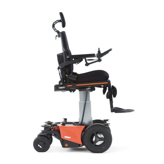
10.1.6 seat lift (optional) The seat lift is centrally mounted into the chassis. With this lift the seat can be raised step less up to 400mm. This enables the user to have more freedom of movement, not only in horizontal area, but also in the vertical area. The seat lift can be stopped at any height and will be automatically locked in position. -
Page 22: Seat
10.2 seat The seating system is designed to optimize the seating comfort to the user. It can be adjusted in seat depth and seat width. A rail on each side provide mounting point for accessories like hip supports or safety belts. The seat pan is flat so other seating cushion can be fitted on to the seat as well. -
Page 23: Seat Tilt (Optional)
10.2.3 seat tilt (optional) The seat tilt can be used to release pressure. The tilting angle is from 0 to 50°. The tilt can also be used when driving down a slope for compensating the negative seat angle. This provides a more stabile seat position and safe driving. -
Page 24: Upholstered Backrest
10.2.4 upholstered backrest The upholstered backrest is available in different lengths and width sizes to give the users maximum support and comfort. The cloth is available as 3D mesh or breathing but waterproof cloth. 10.2.5 power recline backrest (optional) The power recline backrest can be set from 85° to a flat horizontal position. It gives the user the possibility to move into a laying position or a very active sitting position. -
Page 25: Upholstered Armrest
10.2.6 upholstered armrest The upholstered armrests of the seat provide good and comfortable support of the arm which result in a stabile seating position. The armrest has a soft upholstery on the top side. The arm rests come in 320 mm or 400mm length. A biomechanical mechanism makes sure the armrests are always in a good position to supply optimal support. -
Page 26: Upholstered Headrest (Optional)
If the legrest is stretched over 45° the driving speed will automatically be reduced for safety reasons. When stretching the legrest always check if there are no obstructions close to the wheelchair. Especially in the front of the wheelchair. When stretching the legrest, the wheelchair will get longer. This has influence on the driving characteristics of the wheelchair. -
Page 27: Upholstered Calf Support (Optional)
10.2.10 upholstered calf support (optional) The upholstered calf supports are adjustable in height, depth, width and angle. They give additional support when using a powered legrest. 10.2.11 upholstered lateral support (optional) The optional upholstered lateral support offer support on the upper body. The supports are adjustable in height, width, depth and angle. -
Page 28: Upholstered Hip Support (Optional)
10.2.12 upholstered hip support (optional) The upholstered hip supports offer side support to your hips or upper leg. The support is adjustable in height, depth, width and angle. The soft pads offer good and comfortable support. upholstered hip supports The hip supports can be taken away for transferring in or out of the wheelchair, without losing the settings. -
Page 29: The Controls
The EvO Lectus wheelchair has a side steering control unit, which is either mounted on the left- or right armrest. The joystick module can be mounted on a fixed bracket or on an (optional) swing away mechanism. This system enable you to sit close to a table. -
Page 30: The First Set Up
11. the first set up Before using, the wheelchair needs to be adjusted and set up for the user. In this chapter we will explain all the setup which needs to be done before the first drive. before using the wheelchair it is vital to make the right set up for the user. A non proper set up of the wheelchair might lead to uncontrolled driving which can result in personal or material damage. - Page 31 the best way is to measure the distance between the ring and the end of the tread in mm. Make sure that the spring settings in the front are identical. The same for the two rear springs. to soft settings of the spring will result in a very spongy behavior of the chassis.
-
Page 32: Damper Setting
11.1.2 damper setting The spring damper unit has a red adjustment wheel on the end of the damper. This wheel adjusts the rebound speed of the spring. turning the red knob clockwise will make the movement of the piston going out again faster. -
Page 33: Seat Adjustments
11.2 seat adjustments Before using the wheelchair, the seat must be set to the right size for the user. Most of the time this will be done by your local supplier, together with your therapist. A well adjusted seat will give you optimum support and comfort. 11.2.1 seat depth To adjust the seat depth we have to do the following steps: step 1: pull off the seat cushion. - Page 34 Therefore we strongly advise you to have it done by your local authorized Karma dealer. step 7: tighten the screws of the legrest frame to fixate the seat depth.
- Page 35 step 8: mount the side rails into position and tighten the bolts. with every seat depth comes a different length of seat rail. Pre-order the right length of rail first before changing the seat depth. step 9: place the top seat panel back into position and tighten the screws. Now, the seat cushion can be put back in to place.
-
Page 36: Seat Width
11.2.2 seat width to increase the seat width, additional extension rail can be mounted. Please notice the following steps to increase the seat width: step 1: take off the cushion step 2: loosen the screws of the side rail (A) and remove them. step 3: unpack the additional extension rail... -
Page 37: Armrest Width
step 4: place the extension rail in to position and place the longer mounting bolt which come with the extension rail. step 5: tighten the bolts and place the wider seat cushion on the set pan. 11.2.3 armrest width the distance between both armrest can be changed in steps of 50mm. To change the distance you must do the following steps: step 1: remove the rear cover of the backrest. - Page 38 step 2: loosen and remove the two bolts using an 5mm Allan key. step 3: remove the spring lock pin from the ball joint. step 4: detach the parallel bar from the armrest.
- Page 39 if the parallel bar is removed the armrest will fall down. So before removing the parallel bar, make sure you hold the armrest with one hand whilst removing the parallel bar with the other hand. step 5: pull out the armrest axle step 6: take of the bearing ring (R) step 7: add or remove the spacer of the axle and put the bearing back.
-
Page 40: Armrest Height
step 8: put the axles back into the backrest frame and tighten the two central bolts. step 9: connect both parallel bars and secure them with the locking pin. step 10: put the backrest cover back on the frame. Now the armrests are set in to a different width position. 11.2.4 armrest height The armrest height can be adjusted left and right independently. -
Page 41: Armrest Angle
step 2: set the armrest angle by using an 5mm Allan key. By rotating it clockwise the armrest height will increase. Counterclockwise the armrest height will be reduced. step 3: once the right height is set, fixate this position by tightening the locking bolts again. -
Page 42: Armrest Depth
step 2: loosen up the bolt (C) slightly until the armrest starts to move. if the second bolt is loosened the armrest will fall down. So loosening the second bolt, make sure you hold the armrest with one hand whilst loosening the bolt with the other hand. -
Page 43: Armrest Inside Angle
step 2: slide the armrest backward ort forwards into the required position. step 3: tighten the four bolts. The armrest is set. 11.2.7 armrest inside angle The armrest pad can be sideways adjusted over an angle of 15 degrees. to set the armrest inside angle take the following steps: step 1: loosen up nut (E) underneath the armrest pad using a 10mm wrench head. -
Page 44: Legrest Length
11.2.8 legrest length the legrest length is step less adjustable. Both left and right length is separately adjustable. To set the right length follow the next steps: step 1: loosen up the bottom legrest (A) bolt first, using a 5mm Allan key. step 2: slowly loosen up the top end bolt (B). -
Page 45: Legrest Angle
11.2.9 legrest angle the legrest angle can be mechanically set following the next steps: step 1: loosen up the bolt (F) on the telescopic tube of the legrest using a 5mm Allan key. Just open it far enough so you feel it is starting to move. by loosening the bolt of the telescopic tube, the legrest might suddenly start to move down. -
Page 46: Footplate Angle
11.2.10 footplate angle The footplate angle can be adjusted for the left and right footplate separately. The setting is step less. To adjust the angle follow the next steps: step 1: insert the 4mm Allan key into the adjustment screw inside the footplate. -
Page 47: Calf Support Settings
11.2.11 calf support settings Optionally, calf supports can be mounted on the legrest. The calf supports are fully step less adjustable. 11.2.11.1 adjusting the height of the calf support step 1: loosen up the four bolts (G) using a 5mm Allan key, until the calf support starts to slide in the rail. - Page 48 step 1: loosen up the four bolts of the calf support pad, using a 5mm Allan Key. step 2: slide the pad into the right position on the rail. step 3: tighten the four bolt. Repeat the same for the other calf support pad. 11.2.11.3 adjusting the depth and angle of the calf support pads.
-
Page 49: Headrest Settings
11.2.12 headrest settings The optional head rest is fully step less adjustable to suit the user's needs. It can be taken off without losing its setting. detached from backrest high position low position 11.2.12.1 sideways adjustment headrest the head rest has an optional rail for a sideways off centre adjustment. to set this adjustment, take the following steps: step 1: loosen the 4 bolts (L) using a 5mm Allan key. - Page 50 11.2.12.2 headrest depth, height and angle adjustment. the headrest has a friction system containing three rotation joints. By moving each rotation joint you can set the height, depth and angle of the headrest all at the same time. to set the headrest in its right position, follow the next steps: step 1: take off the rubber covers (K) of the three joints step 2: loosen up the bolts using a 6mm Allan key.
-
Page 51: Hip Support Settings
if you loosen up the bolts too much, the headrest will fall down. this might cause a little shock reaction on the user in the wheelchair. It is better to loosen the bolts bit by bit and every time try to move the headrest. the friction will keep it stabile. -
Page 52: Setting The Height Position Of The Hip Support
11.2.13.2 setting the height position of the hip support to set the height of the hip support, take the following steps: step 1: loosen the lever knob (N) and lift up the hip support into the right height position. step 2: loosen the bolt (O) of the fixation ring using a 4mm Allan key and reposition this ring against the mounting block as a stopper. - Page 53 step 4: remove the rubber covers (P) of the friction joints. step 5: loosen the friction bolts (Q) so the padding can be moved. step 6: tighten the frictions bolts. Now the position is fixed. step 7: punt the covers back on to the friction joints. if you loosen up the bolts too much, the hip support might start to suddenly move.
-
Page 54: Lateral Support Settings
11.2.14 lateral support settings the optional lateral support can be adjusted step less in height, depth, width and angle. 11.2.14.1 set the height of the lateral support. step 1: loosen up the bolts (R) using a 5mm Allan key. step 2: move the lateral support in to the required height. step 3: tighten the bolts. -
Page 55: Positioning Belts
step 1: loosen the bolts (S) of the friction joints. step 2: move the pad into the required angle, depth and width. step 3: tighten the bolts to fixate the setting. 11.3 positioning belts the optionally positioning belt can be adjusted in length and anchoring point. To change the setting simply follow the next steps: step 1: loosen the bolts (T) using a 4mm Allan key. -
Page 56: Control Settings
11.4 control settings the side control joystick module is adjustable in depth, height and angle. to set the depth take the following steps: 11.4.1 height adjustment side control: To set the height adjustment of the side control follow the next steps: step 1: loosen the bolts (V) using a 3mm Allan key. -
Page 57: Control Panel
12 control panel The wheelchair uses a color screen joystick module. With this joystick module all functions of the wheelchair can be controlled. This joystick module can be mounted on the left or right armrest or even as an integrated desktop unit. -
Page 58: Display
12.3 display The color LCD screen is split into 3 areas of information. The Top Bar, the Base Bar and the Main Screen Area. 12.3.1 battery indicator (top bar) This displays the charge available in the battery and can be used to alert the user to the status of the battery. -
Page 59: Profile Name (Main Screen)
12.3.3 profile name (main screen) The profile name shows in which drive profile you are at the moment. The name of the profile can be programmed to your wishes by your local supplier. The wheelchair can have up to 8 different driving profiles. Each profile is set to a certain environment you want to drive in. -
Page 60: Speed Bar (Main Screen)
12.3.6 speed bar (main screen) This speed bar displays the current maximum speed setting. It contains 5 steps in speed. These steps can be selected using the speed buttons, explained in the chapter "Buttons" 12.3.7 inhibit (main screen) If the speed of the wheelchair is being limited;... -
Page 61: Additional Options (Main Screen)
12.3.9 additional options (main screen) Additional screens can show the additional options of the electronic system. for example: Bluetooth, environmental control, mouse function. for more detailed information n about these options, [pleas contact you local supplier. 12.3.10 message screen (main screen) The joystick module displays warning icons and informational messages, in a dedicated message window. - Page 62 12.3.10.3 sleep message This symbol will be displayed for a short time before the R-net enters into a sleep state. 12.3.10.4 joystick deflected message this message is show if the wheelchair is started up and the joystick is not in its zero position. If you let go of the joystick, the system will start up normally and the message disappears.
-
Page 63: Current Profile (Base Bar)
12.3.11 current profile (base bar) The currently selected Profile is shown in numeric form. 12.3.12 motor temperature (base bar) This symbol is displayed when the control system has intentionally reduced the power to the motors, in order to protect them against heat damage. - Page 64 wheelchair in locking mode To unlock the wheelchair: - If the control system has been switched off, press the ON/OFF button. - Deflect the joystick forwards until the control system beeps. - Deflect the joystick in reverse until the control system beeps. - Release the joystick, there will be a long beep.
-
Page 65: Buttons
12.4 buttons The joystick module has several button which will be explained below. 12.4.1 on/off button The On/Off button applies power to the control system electronics, which in turn supply power to the wheelchair’s motors. Do not use the On/Off button to stop the wheelchair unless there is an emergency. -
Page 66: Mode Button
12.4.5 mode button The Mode button allows the user to navigate through the available operating modes for the control system. The available modes are dependent on programming and the range of auxiliary output devices connected to the control system. 12.4.6 profile button The Profile button allows the user to navigate through the available Profiles for the control system. -
Page 67: Left Indicator Button And Led
12.4.9 left Indicator Button and LED This button activates and de-activates the wheelchair’s left indicator. Depress the button to turn the indicator on and depress the button again to turn it off. When activated the left indicator LED will flash in sync with the wheelchair’s indicator(s). -
Page 68: R-Net Connectors
The Joystick Module is supplied with rubber bungs that must be inserted into the Jack Socket when no external device is connected. 12.6 R-net Connectors To connect the Communication Cables: • Holding the connector housing, firmly push the connector into its mate until you can no longer see the yellow plastic. -
Page 69: Joystick
12.6 joystick The joystick is primarily used to drive the wheelchair. just push the joystick into the direction you want to drive and the wheelchair will start to move in that direction. The secondary purpose of the joystick is to navigate through men menu of the wheelchair. -
Page 70: Electric System
13 electric system 13.1 batteries The wheelchair has two serial connected 12 volt maintenance free batteries for the power supply. The capacity of the batteries can be 60, 72 or 85 Amps. The batteries are fitted in the center of the chassis to arrange a low centre point of gravity. -
Page 71: Fuses
If the fuse in blown, please contact your local authorized supplier. He should check the wheelchair first before replacing the main fuse. The fuse only blows if a serious problem occurs. Only use original spare part fuses of Karma. Using other fuses might damage the electronic system or even cause fire. -
Page 72: Using The Wheelchair
14 using the wheelchair 14.1 general warnings and advices Please read this section of the manual very carefully as it contains issues related to safety and possible hazards. ● When the user is driving the wheelchair for the first time, the supplier has to make sure that the maximum driving speed and curving speed are set in a slow mode. -
Page 73: Use In Combination With Other Products
This has to be checked by watching these parts when tilting the chair. Changes which are made by third parties are not covered by the warranty and responsibility of Karma Medical. 14.3 hot and cold surfaces Some parts of the wheelchair can reach high temperatures when exposed to direct sun. -
Page 74: Danger Of Pinching
14.4 danger of pinching User Special care has been taken to make sure that the chance that the user pinches him or herself while seated in the wheelchair is minimal. However there are few situations that might lead to injury. Special caution has to be taken under the following circumstances;... -
Page 75: Surroundings
14.5 surroundings Special care has been taken to make sure that the change that the surroundings pinches him or herself is minimal. However there are few situations that might lead to injury. Special caution has to be taken under the following circumstances;... -
Page 76: Use On Slopes: Driving On Downhill Slopes
● Have the wheelchair checked on a yearly basis by your supplier. ● Do not change the programmed driving characteristics of your control unit, as it is specific for the situation of the user. If any adjustment is required because of a change of circumstances, please contact your supplier. Always make sure that, when positioned on slopes, the brakes are attached (no Freewheel). -
Page 77: Use On Slopes: Driving On Uphill Slopes
When driving on downhill slopes with an uneven or slippery surface (for example grass, gravel, sand, ice or snow) you should drive with extra care and attention. When driving on downhill you can use the tilt (if build in) to create a more stabile seating position for yourself. - Page 78 max. acceptable uphill slope When driving on uphill slopes with an uneven or slippery surface (for example grass, gravel, sand, ice or snow) you should drive with extra care and attention. When driving on uphill you can use the tilt (if build in) to create a more stabile seating position for yourself.
-
Page 79: Driving On Sideways Slopes
14.9 driving on sideways slopes Driving on a sideways slope must always be performed with great care. Avoid sudden avoidance maneuvers and never drive at a speed higher than needed to maneuver the wheelchair in a safe and secure way. Avoid holes and bumps as much as possible. -
Page 80: Obstacle Climbing
14.10 obstacle climbing Do not drive the wheelchair over obstacles of a height bigger than 70mm. Driving over tall edges increases the risk of tipping over as well as the risk of damage to the wheelchair. Always aware when climbing obstacles stability of your wheelchair. -
Page 81: Use In Presence Of Electromagnetic Fields, E.g. From Cell Phones
14.11 use in presence of electromagnetic fields, e.g. from cell phones. Use your cell phone only when the wheelchair is switched off. Although the wheelchair is tested and approved for electromagnetic interference, there is a very small change that strong electromagnetic fields from cell phones or some other electrical products lead to unexpected and unpredictable electrical reactions from the wheelchair. -
Page 82: Driving The Wheelchair
15 driving the wheelchair The wheelchair is designed for indoor and outdoor use. When driving indoors, you must be careful when driving in, for example, narrow passageways, when passing through doors and entryways as well as when using elevators, ramps, etc. -
Page 83: Driving Technique
3. Set an appropriate maximum speed by pressing the decrease or increase button until the desired indicator lamp lights up for your type of driving. It is preferable to begin with a low speed. 4. Carefully move the joystick forward to drive forward, and backward to drive backward. -
Page 84: Stopping The Wheelchair
15.3 stopping the wheelchair If you would like to stop simply move the joystick slowly towards the centre and release the joystick. The wheelchair will come to a gentle stop. If you want to stop more quickly, simply let go of the joystick. It will put itself back into neutral position, which makes the wheelchair stop. -
Page 85: Using Additional Function Of The Wheelchair Menu
screen example of the seat function menu By moving the joystick to the left or right you can switch between different powered seat function. One the required seat function is shown on the display, move the joystick forward or backward to activate the seat function in one direction. -
Page 86: Handling The Mechanical Brakes
17 handling the mechanical brakes The drive motors of the wheelchair have electro mechanical brakes. The brake can be release to set the wheelchair into freewheel mode. In freewheel mode the wheelchair can be pushed. this might be necessary to move the wheelchair in certain cases. -
Page 87: Charging The Maintenance Free Batteries
Always make sure that, when positioned on slopes, the brakes are attached (no Freewheel). If the wheelchair is in freewheel mode, there is a risk that the wheelchair might start to move in an uncontrolled way. This might lead to personal or material damage. 18 charging the maintenance free batteries The amount of charge in your maintenance free batteries is depending on a number of factors, including the way you use your wheelchair, the temperature... -
Page 88: Charging Socket
If the maintenance free batteries are fully charged, all ten LED's on the top bar light up. The more energy is used the more LED extinguish, starting on the right side. If only the red LED are still on, it indicates that recharging of the maintenance free batteries is required. - Page 89 charger socket position Exendis Impulse charger The wheelchair can be delivered with an Exendis charger. This charger has a capacity to charge up to 11 ampere. This charger will fully charge the batteries within 8 hours. For more detailed information about the charger and its functions, we refer to the manual which comes with the charger.
-
Page 90: Disposal Of Broken Or Worn Out Batteries
Be sure that the charger plug is pushed fully in position. You will not be able to drive the wheelchair when the charger is connected. If the wheelchair does drive with the charger plugged in, contact your local authorized supplier. In some occasions it might be the case that your local supplier will deliver the wheelchair with a different brand charger. -
Page 91: Transport Of The Wheelchair
19 transport of the wheelchair The wheelchair must only be transported in a vehicle that is approved or adapted for such purposes. It is safest if the wheelchair is separated from the drivers compartment. Transportation in a trailer is also an optional recommendation. - Page 92 Karma Medical Taiwan would always recommend transferring to a car seat within a vehicle, however should this not be possible, the following is the safest method: a. The wheelchair must be positioned in a forward facing position. b. An Unwin restraint system like model Gemini 3 or a different brand with equivalent specification must be used.
-
Page 93: Transportation Guideline
19.1 transportation guideline The wheelchair has a 4-point heavy duty webbing restraint. Using two brackets on the front end and two brackets on each rear side of the chassis. The brackets are indicated with a sticker. The angle of the straps should be around 45° to the horizontal plane. This is in order to have maximum effect in vertical and horizontal direction. -
Page 94: Safety Belt
19.2 safety belt If the user is transported in his wheelchair, it is necessary to use a car safety belt to secure the wheelchair user. positioning of the car safety belts for wheelchair users. The wheelchair has been crash tested using a ……. safety belt model ……. We advise you to use a similar system or a system that is equally specified. - Page 95 The shoulder part (1) of the safety belt should be positioned according to the figure below. shoulder safety belt positioning Please obtain the following points for a optimal personal safety of the wheelchair user: - the pelvic belt should be worn low across the front of the pelvis, so that the angle of the pelvic belt is within the preferred zone of 30°...
- Page 96 picture of improper belt fit picture of proper belt fit Please, make sure the following conditions are fulfilled to obtain a safe transportation: - Whenever possible the occupied wheelchair shall be located in a forward-facing configuration and secured by the tie downs in accordance with the WTORS ( wheelchair tie down and occupant- restraint system) manufacturer’s instructions.
-
Page 97: Transportation On An Airplane
- Alterations or substitutions should not be made to the wheelchair securement points or to structural and frame parts or components without consulting the manufacturer. - Only use "gelled electrolyte" batteries on powered wheelchairs when used in a car. 19.3 transportation on an airplane When transporting your wheelchair by air, you should primarily pay attention to the following three things: 1. -
Page 98: Maintenance And Repairs
20 maintenance and repairs The user and attendant have to take care of some maintenance, service and occasionally fault finding activities. Other activities as described in this paragraph should be carried out under supervision of your authorized dealer. 20.1 battery charging This wheelchair is provided with two maintenance free batteries. -
Page 99: Long Term Storage
20.3 long term storage The battery may be stored in an unheated room but it should be charged at least once a month for maintenance purposes. when the wheelchair is stored for a long term, we advise you to disconnect the batteries from the wheelchair. -
Page 100: Tools
20.4 tools The wheelchair comes with a tool kit to be able to adjust most settings. the toolkit includes: ● a set of Allan keys ● a flat/Phillips screw driver ● a socket wrench 11 and 13 mm. Some repairs may require tools other than those supplied with the wheelchair. -
Page 101: Wheels And Tires
20.5 wheels and tires Check at regular intervals that the wheelchair’s tires have the correct tire pressure. Check regularly that the tire pressure is okay. we suggest to check the tire pressure at least every 4 weeks. type of tire tire size recomm. -
Page 102: Cleaning
20.6 cleaning Regular care and maintenance will prevent unnecessary wear and damage to your wheelchair. The following is general advice recommended by Karma. For severe soiling of the upholstery or damage to the surface finish, contact Karma or your local authorized supplier for information. -
Page 103: Brake Release, Freewheel Mode
20.7 brake release, freewheel mode Check regularly, approximately once a month, that the brake release and the brake release lever are working properly. When the brakes are released, it should not be possible to drive the wheelchair. testing the brake release 20.8 battery replacement step 1: Place the wheelchair on a level surface and, if possible, raise the seat lift for better access. - Page 104 step 9. place the batteries inside the battery box. Make sure the cables are not jammed between the battery and the chassis! step 10. put the battery covers back in to place. step 11. secure the battery covers with the hand screw. If you are not capable of replacing the batteries by yourself or you don't feel comfortable doing it, please contact you r local authorized supplier for help.
-
Page 105: Replacing The Main Fuse
5. place the rubber cover on to the fuse holder. place of the main fuse main fuse Only us an original and official spare part fuse from Karma. Other fuses might cause errors again or even fire. Wear protective gear when replacing the fuse, like safety goggles and hand gloves. -
Page 106: Refurbishment And Re-Use Of The Product
The wheelchair will be refurbished according to a refurbishment guideline of Karma. This includes the replacement of all upholstery parts, a total disinfection of the product and a complete technical check of the wheelchair and its accessories. -
Page 107: Trouble Shooting
Note that this guide cannot describe all the problems and events which may occur and you should always contact your local authorized supplier or Karma incase of doubt. -
Page 108: Diagnostics R-Net Lcd
Incorrect or poorly performed repair works may make it dangerous to use the wheelchair. Karma accepts no liability for any personal injury or damage to the wheelchair and its surroundings that occurs on account of incorrect or... -
Page 109: Technical Specifications
24 technical specifications length [L]: 1200 mm width [W]: 610 mm height [H]: 1115 mm horizontal location of axle [A]: 345 mm transportation size: length [LT]: 880mm height [HT]: 770mm width [WT]: 610mm... - Page 110 DATA General product name EvO Lectus wheelchair class Class B expected service life > 7 years Sizes min. max. length, mm 1200 width, mm height, mm 1115 weight, kg horizontal location of axle, mm Smallest size for transportation length 880 mm...
-
Page 111: Accessories
Every day we design new accessories to improve the flexibility of our products. Contact your local authorized Karma supplier for more information on the accessories which are available for your wheelchair. Should you have a good suggestion for a new accessory, do not hesitate to contact us. - Page 112 NOTES:...
- Page 113 Through our dedication and our mindfulness, we look forward to bringing more confidence, joy, and love for life to those with physical abilities around the world. Karma Medical is continuously improving their products and accessories. Changes might take place without further notice.
Need help?
Do you have a question about the EvO Lectus and is the answer not in the manual?
Questions and answers