Sennheiser Digital 9000 Instruction Manual
Hide thumbs
Also See for Digital 9000:
- Specifications & manufacturer installation manual (110 pages) ,
- Quick start manual (2 pages)
Table of Contents
Advertisement
Quick Links
Advertisement
Table of Contents

Related Manuals for Sennheiser Digital 9000


Summary of Contents for Sennheiser Digital 9000
- Page 1 Digital 9000 Digital 9000 System instruction manual...
-
Page 3: Table Of Contents
B 60 battery pack ..................27 B 61 battery pack ..................28 L 60 charger ....................29 Preparing the Digital 9000 system for use ......31 Preparing the EM 9046 receiver for use ..........32 Setting up the receiver or mounting it into a 19" rack .....32 Connecting devices to the analog audio outputs .......33... - Page 4 Overview of the status displays .............96 Overview of the menu items ..............97 Using the L 60 ................101 Cleaning and maintaining the Digital 9000 system ..105 If a problem occurs ............... 109 EM 9046 receiver ..................110 Digital 9000...
- Page 5 Contents SKM 9000 radio microphone ..............111 SK 9000 bodypack transmitter .............111 L 60 charger .....................112 Specifications ................. 113 Manufacturer Declarations ..........124 Digital 9000...
- Page 7 Digital 9000 Important safety instructions ME 9002 ME 9004 ME 9005 A 9000 AB 9000 AD 9000 GZL 9000-A5 GZL 9000-A10 GZL 9000-A20 B 60 BA 60 SKM 9000 SKM 9000 COM EM 9046 L 60 EM 9046 DRX EM 9046 AAO...
-
Page 8: Important Safety Instructions
17. Do not expose this equipment to dripping or splashing and ensure that no objects filled with liquids, such as vases, are placed on the equip- ment. 18. The mains plug of the power supply cord shall remain readily accessi- ble. Digital 9000... - Page 9 Danger of hearing damage due to high volumes This is a professional receiver. Commercial use is subject to the rules and regulations of the trade association responsible. Sennheiser, as the manu- facturer, is therefore obliged to expressly point out possible health risks arising from use.
- Page 10 In extreme cases, they may even present a risk of • explosion, • fire development, • heat generation, • smoke or gas development. Sennheiser does not accept any liability for damage arising from abuse or misuse. Keep away from children. Only charge rechargeable batteries...
- Page 11 Store the product in a cool Remove the and dry place at room rechargeable batteries if temperature (approx. 20 °C/ the product will not be 68 °F). used for extended periods of time. Digital 9000...
-
Page 13: Digital 9000 System Overview
KA 9000 COM EM 9046 CAB MKE 1 MKE 2 CI 1-4 Digital 9000 – System overview ..........11 CI 1-4 line/instrument cable for the EM 9046 receiver ..............12 SK 9000 bodypack transmitter ........15 Antennas and antenna boosters ........12 B 60/B 61 battery packs ........... 16 SKM 9000 radio microphone/ BA 60/BA 61 accupack ............ -
Page 14: Em 9046 Receiver
Digital 9000 – System overview The Digital 9000 system The Digital 9000 system is characterized by its high transmission reliabil- ity and easy of use. The large switching bandwidth as well as various dif- ferent connection possibilities offer great flexibility in daily use. -
Page 15: Skm 9000 Radio Microphone/Sk 9000 Bodypack Transmitter
Digital 9000 – System overview SKM 9000 radio microphone/ SK 9000 bodypack transmitter The SKM 9000 and SK 9000 transmitters offer great ease of use and can easily be adapted to any transmission situation: • Rugged housing • Input gain adjustable in 3 dB steps •... -
Page 16: Delivery Includes
Delivery includes Delivery includes You can make up your own Digital 9000 system with the following compo- nents: EM 9046 receiver 1 EM 9046 receiver fixedly equipped with - PSU power supply unit - CCC core clock controller - ASP antenna splitter... -
Page 17: Skm 9000/Skm 9000 Com Radio Microphone
25. KA 9000 COM command adapter for the SK 9000 bodypack transmitter 1 command adapter 1 instruction manual CI 1-4 line/instrument cable for the SK 9000 bodypack transmitter 1 CI 1-4 line/instrument cable 1 instruction manual Digital 9000 | 15... -
Page 18: B 60/B 61 Battery Packs
(EU, UK or US version). One NT 3-1 mains unit can power up to four chargers. A list of accessories can be found on the Digital 9000 product page at www.sennheiser.com. For information on suppliers, contact your local Sennheiser partner: www.sennheiser.com >“Service &... -
Page 19: Product Overview
Multiple channel selection button 9 sys L esc button Display panel Channel button N live button (for selecting the “live” C esc operating mode) O sys button (for configuring the system) P ch button (for configuring the channels) Digital 9000 | 17... - Page 20 DRX, modules. The configuration shown is an example configuration. The inter- changeable modules are highlighted in color. Your Sennheiser service partner can configure the EM 9046 as follows: • 1 to 8 EM 9046 receiver modules • 1...
- Page 21 Audio signal of this channel is bound to the encryption EM 9046 Diversity evaluation display (true bit diversity) Antenna signal display (dBm) “HD”/“LR” and “Command” display “Encryption” display Audio level display (dBfs) Display for remaining operating time of the transmitter Digital 9000 | 19...
- Page 22 WORD CLOCK IN BNC socket 9, the digital audio output of the EM 9046 automatically synchronizes with it and the clock lights up constantly. if off The EM 9046 receiver generates its own word clock signal. 20 | Digital 9000...
-
Page 23: Antennas And Antenna Boosters
If you are using the antennas/antenna booster with the EM 9046, the “Filter” rotary switch allows you to set the desired frequency range (“A1” ... “A8” or “B1” ... “B8”). Digital 9000 | 21... -
Page 24: Gzl 9000 Antenna Cable
COMMAND button radio microphone is operational (SKM 9000 COM) Antenna Display panel Catches Infra-red interface for accupack/battery pack Accupack battery pack for 2 AA size cells Body of radio microphone 9 DOWN button 0 UP button 22 | Digital 9000... - Page 25 MMK 965-1 cardioid/super-cardi- permanently polarized oid, switchable KK 204 (Neumann) cardioid condenser KK 205 (Neumann) super-cardioid condenser You can also use your radio microphone together with the micro- phone heads of the ew G3 and 2000 series. Digital 9000 | 23...
-
Page 26: Sk 9000 Bodypack Transmitter
7 SET 3-pin special audio socket button 8 UP button - Sennheiser microphones Catches - CI 1-4 Sennheiser instrument cable for accupack/battery pack - KA 9000 COM command adapter Snap-in elements 2 ON/OFF button for accupack/battery pack with ESC function (cancel) - Page 27 ME 105 super-cardioid HSP 2 omni-directional HSP 4 cardioid Sennheiser CI 1-4 line/instrument cable ¼’’ (6.3 mm) jack plug (silent plug) to 3-pin special audio connector KA 9000 COM command adapter for the SK 9000 Digital 9000 | 25...
-
Page 28: Transmitter
Product overview bodypack transmitter 3-pin special audio connector 3-pin special audio socket COMMAND button Connection cable, length: 1.6 m BA 60 accupack Charging and data contacts Antenna Snap-in elements 26 | Digital 9000... -
Page 29: Ba 61 Accupack
Product overview BA 61 accupack Snap-in elements Guide rail Charging and data contacts B 60 battery pack Battery compartment for 2 Antenna AA size batteries Data contacts Snap-in elements Digital 9000 | 27... -
Page 30: B 61 Battery Pack
Product overview B 61 battery pack Snap-in elements Guide rail Data contacts Battery compartment for 3 AA size batteries Cover 28 | Digital 9000... -
Page 31: L 60 Charger
0-70% orange Accupack is being charged, capacity obtained is approx. 70-100% green Accupack is fully charged, capacity is continuously monitored flashing red Error, charging is aborted (accupack is e.g. defective or overheated) Digital 9000 | 29... -
Page 33: Preparing The Digital 9000 System For Use
MKE 1 MKE 2 CI 1-4 Preparing the Digital 9000 system for use ......31 Adjusting the receiving antennas/antenna boosters ..40 Preparing the SKM 9000 radio microphone for use ...40 Preparing the EM 9046 receiver for use ...... 32 Changing the microphone head .......... -
Page 34: Preparing The Em 9046 Receiver For Use
Preparing the Digital 9000 system for use Preparing the EM 9046 receiver for use Setting up the receiver or mounting it into a 19" rack Setting up the receiver on a flat surface CAUTION Risk of staining of furniture surfaces! Furniture surfaces can be treated with varnish, polish or synthetics which might cause stains when they come into contact with other synthetics. -
Page 35: Connecting Devices To The Analog Audio Outputs
Preparing the Digital 9000 system for use To mount the receiver into a 19" rack: Mount rack rails that are designed to carry the total weight of the EM 9046. Slide the receiver onto the rack rails and screw it to the front of the rack using 2 screws per side (screws to be ordered separately). -
Page 36: Connecting Devices To The Digital Audio Outputs
Preparing the Digital 9000 system for use Connecting devices to the digital audio outputs When equipped with an DAO digital audio out module, the EM 9046 receiver has 8 digital balanced audio outputs. The signals are output in AES3 format. -
Page 37: Daisy Chaining Receivers
(see next section). This diagram illustrates a convenient way of daisy chaining the receivers. Sennheiser recommends using an external switch to connect the receivers in a star topology (see “Connecting receivers in a network” on page 36). -
Page 38: Connecting External Word Clock Signals
Preparing the Digital 9000 system for use Connecting external word clock signals The EM 9046 receiver supports external word clock sampling rates of EM9046 44.1 kHz, 48 kHz, 88.2 kHz and 96 kHz. If you have installed a MAN card, you can alternatively use the card‘s word clock as external word clock gen-... - Page 39 Preparing the Digital 9000 system for use – You use both network sockets (LAN UP DOWN) of the receivers. This causes the receivers to act as a switch. You do not require an external switch. – The Spanning Tree Protocol (STP) and/or the Rapid Spanning Tree Protocol, (RSTP) are used to detect and deactivate redundant paths in the local network.
-
Page 40: Connecting The Receiver To The Mains
Preparing the Digital 9000 system for use Connecting the receiver to the mains CAUTION Damage to the device due to electric current! If you connect the receiver to an unsuitable power supply, this can cause damage to the device. Use the supplied mains cable to connect the receiver to the mains (100 to 240 V AC, 50 or 60 Hz). -
Page 41: Preparing The A/Ab/Ad 9000 Antennas And/Or Antenna Boosters For Use
Preparing the Digital 9000 system for use Preparing the A/AB/AD 9000 antennas and/or antenna boosters for use Antennas and antenna boosters of the Digital 9000 series are available in two variants: A1–A8 and B1–B8. Select the booster variant (A1–A8 or B1–B8) whose frequency range... -
Page 42: Connecting The Receiving Antennas/Antenna Boosters
Preparing the Digital 9000 system for use Connecting the receiving antennas/antenna boosters Use GZL 9000 antenna cables. Sennheiser GZL 9000 antenna cables are available in lengths of 5 m, 10 m and 20 m. A/AB/AD 9000: Connect the RF out... - Page 43 Preparing the Digital 9000 system for use Inserting batteries into the B 60 battery pack Insert the batteries (see diagram). Observe correct polarity when insert- ing the batteries. Only insert high-quality AA size batteries (e.g. lithium or alkaline batteries) into the B 60 battery pack. Do not insert individual rechargeable batteries such as NiMH cells.
-
Page 44: Changing The Microphone Head
Preparing the Digital 9000 system for use Changing the microphone head CAUTION Damage to the microphone head! If you touch contacts, they can become dirty or damaged. Do not touch the contacts of the radio microphone nor the contacts of the microphone head. - Page 45 Preparing the Digital 9000 system for use CAUTION Damage to the bodypack transmitter and/or the accupack/battery pack! If you touch the following contacts, they can become dirty or damaged: • Contacts for supply voltage and data contacts of the bodypack transmitter •...
- Page 46 For an overview of suitable microphones, refer to the product over- view on page 25. Connect the 3-pin special audio connector of the Sennheiser microphone or the Sennheiser CI 1-4 line/instrument cable to the 3-pin special audio socket 1. Lock the connector by screwing down the coupling ring.
-
Page 47: Connecting The Antenna
KA 9000 COM to the 3-pin special audio socket of the SK 9000. Connect the 3-pin special audio connector of the Sennheiser microphone or the Sennheiser CI 1-4 line/instrument cable to the 3-pin special audio socket of the KA 9000 COM. Digital 9000... -
Page 48: Preparing The L 60 Charger For Use
Preparing the Digital 9000 system for use Preparing the L 60 charger for use Cascading several chargers Up to 4 L 60 charger can be cascaded together and can be powered by the NT 3-1 mains unit. Prepare the L 60 chargers: –... - Page 49 Preparing the Digital 9000 system for use To fix the charger securely in place: Fix the charger by screwing screws (fillister head self-tapping screws as per DIN 7049, ST 3.5 x 32) through the four holes at the bottom of the charger.
-
Page 51: Using The Em 9046
“sys”, “ch”, “live” – operating modes at a glance ..51 Extended menu “Transmitter setup” .......80 Basic functions of the Sennheiser operating menu ..51 Displays of the Sennheiser operating menu ....52 “live” operating mode – Using a configured system .83 Error and warning messages ..........53 “sys”... -
Page 52: Using The Em 9046 Receiver
The receiver’s operating system is loaded. During loading, the LED of the standby button flashes red and the display panel shows the Sennheiser start screen. Then, an automatic calibration of the cable attenuation is performed (see page 64). Once the operating system is fully loaded, the receiver is in “live” oper- ating mode. -
Page 53: Sys", "Ch", "Live" - Operating Modes At A Glance
“sys” operating mode can be found from page 55 onwards. Basic functions of the Sennheiser operating menu A special feature of the Sennheiser 9000 series is the straightforward, intuitive operating concept. As a result, you can act quickly and precisely –... -
Page 54: Displays Of The Sennheiser Operating Menu
“live” operating mode. Displays of the Sennheiser operating menu The Sennheiser operating menu consists of the menu selection in the upper part, where you can select and call up menu items, and the... -
Page 55: Error And Warning Messages
(here by way of example of the “Audio output level” menu item): Main screen EM 9046 AAO EM 9046 DAO Analog multicore Error and warning messages Error and warning messages are displayed in white letters. The display panel is highlighted in orange. Digital 9000 | 53... - Page 56 “System check” menu item in the extended menu “Service setup” of the system menu. For more information, refer to page 69. 54 | Digital 9000...
-
Page 57: Sys" Operating Mode - Configuring The System
Calls up the main menu System setup “System setup” Loads the factory default Factory reset settings Date & time Adjusts the date and time Op hours Displays the operating hours Displays the event logs System check Displays the system status Digital 9000 | 55... -
Page 58: Main Menu "System Setup
To perform a frequency scan: Call up the “Frequency scan” menu item. If a frequency scan has already been performed, the last activated booster frequency range is highlighted in blue. 56 | Digital 9000... - Page 59 758 750 774 774 798 MHz Interference active zone HD start full scan Start scan RF IN Noise Level Zone HD/LR LR/HD Interference levels Interference levels Activated booster of antenne A of antenne B frequency range Digital 9000 | 57...
- Page 60 Range)”: Transmission of an audio signal whose bit rate is reduced – before transmission – by an audio data compression tech- nique (SeDAC, Sennheiser Digital Audio Codec). This compression tech- nique provides excellent audio quality and a large transmission range.
- Page 61 Finish the frequency scan and store the previously activated range by button F. pressing the Assign frequency presets to the channels as described in the next sec- tion. Digital 9000 | 59...
- Page 62 Freq measured Range: 774 - 798 MHz freq scan values Name: „CH1“ RF A: -104.5 dBm RF B: -106.5 dBm ch_1 Selected frequency preset 774.000 778.000 782.000 786.000 790.000 794.000 798.000 MHz “HD” “HD/LR” “LR/HD” “LR” 60 | Digital 9000...
- Page 63 B are additionally displayed at the top margin of the screen. The interference levels of both antennas should be within or below the interference zone that is required or useful for this channel (see page 56 and 58) and should be as low as possible. Digital 9000 | 61...
- Page 64 Perform a walk test to check the reliability of your transmission links (see page 79). Change the transmission mode for the channels with reception prob- lems and then synchronize the transmitters and the receiver again. If the reception problems persist, select a different booster frequency range. 62 | Digital 9000...
- Page 65 Adjust the level of further channels. button F. Your settings are stored and the receiver then Press the switches to the main menu. To change to the main menu without storing your settings: button L. Press the Digital 9000 | 63...
- Page 66 “Press SAVE to calibrate” is displayed on the display panel. Pres the button. During the measurement, the channel status display displays “Cali- brating” for each channel. The receiver is muted for approx. 10 seconds. Then the result of the measurement is displayed as follows: 64 | Digital 9000...
- Page 67 The settings of the following menu items are saved: Menu Menu item Page Main menu Output level “System setup” Word clock Network | name of the network Network | IP settings Brightness Extended menu Date & time | selected time zone “Service setup” Digital 9000 | 65...
- Page 68 IP address automatically or to enter the IP address manually. In addition, this menu item displays the unchangeable MAC addresses of the network interfaces of your receiver. “Brightness” – Adjusting the brightness brightness 66 | Digital 9000...
-
Page 69: Extended Menu "Service Setup
Word clock 96 kHz setup” Network | EM9046_1 name of the network Network | Auto IP settings Brightness Medium level Extended Date & time | Amsterdam, Berlin, Bern, menu selected time zone Rome, Stockholm, Vienna “Service setup” Digital 9000 | 67... - Page 70 2011-06-14 date & time Via the “Date & time” menu item, you can select your time zone and then adjust the date and time: Timezone Network time: on Date: 2011-07-25 Time: 15:46:32 Dublin, Edinburgh, Lisbon, London 68 | Digital 9000...
- Page 71 • Each synchronization with a transmitter • Software updates “System check” – Displaying current error and warning messages System check: system check Via the “system check” menu item, you can display current error and warn- ing messages. Digital 9000 | 69...
- Page 72 Show alerts Boosters RF-IN B: no booster connected Modules Fans Network Wordclock If you call up the first menu entry “Show alerts”, the warning message is displayed again and the display panel is highlighted in orange. 70 | Digital 9000...
- Page 73 EM 9046 DRX EM 9046 DRX EM 9046 DRX EM 9046 DRX EM 9046 DRX EM 9046 DRX EM 9046 DRX EM 9046 DAN OUT1 EM 9046 AAO OUT2 EM 9046 DAO missing EM 9046 ASP Digital 9000 | 71...
- Page 74 Via the “Firmware” menu item, you can display the firmware versions of the receiver, the boosters and the transmitters and update the firmware of the boosters and the transmitters. The currently installed firmware version of the EM 9046 is displayed in the menu selection (see above). 72 | Digital 9000...
- Page 75 “Updating transmitter ... (ca. xx s)” appears in the menu selection of the receiver’s display panel together with a time specification in seconds. Do not inter- rupt the infra-red transmission during the update process. Digital 9000 | 73...
- Page 76 Place the infra-red interface of the transmitters in front of the infra-red interface of the EM 9046, one after the other, and proceed as described above. To return to the main menu: button L. Press the 74 | Digital 9000...
-
Page 77: Ch" Operating Mode - Configuring Channels
Sets the transmitter’s low-cut Low cut filter Selects the transmitter’s stan- Display dard display Activates/deactivates the Lock transmitter’s lock mode AF source Displays the microphone head (SKM)/audio source and cable emulation (SK) Emulates different instrument Cable cable lengths (SK) Digital 9000 | 75... -
Page 78: Main Menu "Channel Setup
(“U”). If you set the frequency manually, make sure to set a frequency within the current 24 MHz booster frequency range and maintain a frequency spacing of 600 kHz to avoid intermodulation interference. 76 | Digital 9000... - Page 79 KA 9000 COM command adapter. By pressing the COMMAND button on the SKM 9000 COM or KA 9000 COM, you can influence the routing of the audio signal of the receiver’s XLR-3 and sub-D socket D. sockets Digital 9000 | 77...
- Page 80 EM 9046 receiver. In this case, other receivers can receive the RF signal of the transmitters but cannot evaluate the audio signal. To protect the audio signal against eavesdropping from other receivers: 78 | Digital 9000...
- Page 81 - If you perform the walk test as a pair, the second person can monitor the signal quality of the test tone by means of headphones connected to the EM 9046. Digital 9000 | 79...
-
Page 82: Extended Menu "Transmitter Setup
The menu items allow you to adjust settings over the entire value range of the Digital 9000 transmitters. Please note, however, that the actual values are determined by the hardware configuration of your transmitters (fre- quency range, type of microphone head being used (SKM), type of Sennheiser microphone or cable being used (SK), etc.). - Page 83 Range)”: Transmission of an audio signal whose bit rate is reduced – before transmission – by an audio data compression technique (SeDAC, Sennheiser Digital Audio Codec). This compression technique pro- vides excellent audio quality and a large transmission range. The sensitiv- ity to interference is reduced compared to “HD”...
- Page 84 If a transmitter is switched off or transmits on a different carrier fre- quency, “No TX detected” is displayed. “Cable” – Emulating different instrument cable lengths type1 cable 82 | Digital 9000...
-
Page 85: Live" Operating Mode - Using A Configured System
In “live” operating mode, you can also activate channels for synchroniza- tion: Select a channel by pressing the channel 1–8 button M. Proceed as described on page 76. Digital 9000 | 83... -
Page 87: Using The Skm 9000
Using the SKM 9000 Using the SKM 9000 Using the SKM 9000 ..............85 Basic functions of the Sennheiser operating menu ..88 Switching the SKM 9000 on/off ........86 Overview of the status displays ........88 Activating/deactivating the automatic lock mode Overview of the menu items .......... -
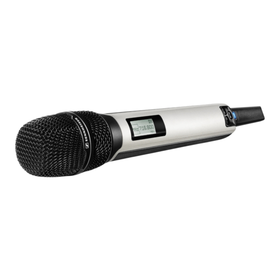
Page 88: Switching The Skm 9000 On/Off
To switch the SKM 9000 on: Keep the ON/OFF button pressed until the Sennheiser logo appears on the display panel 5. ON/OFF button is backlit in blue and the standard display (here: “Frequency”, see page 90) appears on the display panel 5. The radio microphone transmits an RF signal and the transmission mode display “HD”/“LR”... -
Page 89: Activating/Deactivating The Automatic Lock Mode (Autolock)
(read-only function) and call up the “LOCK” menu item in order to deactivate the automatic lock mode. If, however, you try to call up any other menu item, the following display appears on the display panel: Digital 9000 | 87... -
Page 90: Basic Functions Of The Sennheiser Operating Menu
Basic functions of the Sennheiser operating menu A special feature of the Sennheiser 9000 series is the straightforward, intuitive operating concept. As a result, you can act quickly and precisely – even in stressful situations, for example on stage or during a live show or presentation. -
Page 91: Overview Of The Menu Items
25 kHz steps. If you store your setting, the set frequency is automatically assigned to the user-defined frequency preset “U”. The radio microphone then changes from the currently set frequency preset to the frequency preset “U” and transmits on the set frequency. Digital 9000 | 89... - Page 92 1 kHz test tone. This test tone is transmitted instead of the input signal. You can use this function for level matching your system or for the walk test. 90 | Digital 9000...
- Page 93 Via the “Reset” menu item, you can reset the radio microphone to its fac- tory default settings. “Information” – Displaying the firmware version and frequency range Via the “Information” menu item, you can display the firmware version and the transmitter’s frequency range. Digital 9000 | 91...
-
Page 95: Using The Sk 9000
Using the SK 9000 Using the SK 9000 Using the SK 9000 ..............93 Basic functions of the Sennheiser operating menu ..96 Switching the SK 9000 on/off ..........94 Overview of the status displays ........96 Activating/deactivating the automatic lock mode Overview of the menu items .......... -
Page 96: Switching The Sk 9000 On/Off
To switch the SK 9000 on: Keep the ON/OFF button pressed until the Sennheiser logo appears on the display panel C. lights up and the standard display (here: “Frequency”, see page 99) appears on the display panel C. The bodypack transmitter transmits an RF signal and the transmission mode display “HD”/“LR”... -
Page 97: Activating/Deactivating The Automatic Lock Mode (Autolock)
(read-only function) and call up the “LOCK” menu item in order to deactivate the automatic lock mode. If, however, you try to call up any other menu item, the following display appears on the display panel: Digital 9000 | 95... -
Page 98: Basic Functions Of The Sennheiser Operating Menu
Basic functions of the Sennheiser operating menu A special feature of the Sennheiser 9000 series is the straightforward, intuitive operating concept. As a result, you can act quickly and precisely – even in stressful situations, for example on stage or during a live show or presentation. -
Page 99: Overview Of The Menu Items
Information Displays the firmware version and frequency range If you are using the Sennheiser CI 1-4 line/instrument cable, this menu item is hidden If you are using the Sennheiser CI 1-4 line/instrument cable, this menu item is shown Digital 9000... - Page 100 Via the “Gain” menu item, you can adjust the input gain in 3 dB steps from -6 to +42 dB. When you are using Sennheiser microphones or the Sennheiser CI 1- 4 line/instrument cable, the bodypack transmitter automatically detects the type of input signal present and changes the adjust- ment range of the “Gain”...
- Page 101 “Cable” – Emulating different instrument cable lengths Via the “Cable” menu item, you can emulate the lengths of instrument cables in 3 steps. If you are using the Sennheiser CI 1-4 line/Instrument cable, the “Cable” menu item is shown. “RF mode” - Adjusting the transmission mode “RF...
-
Page 103: Using The L 60
Digital 9000 Using the L 60 Using the L 60... - Page 104 ... 2 BA 61 or ... 1 BA 60 and 1 BA 61. Insert the accupack into one of the charging compartments make sure that it locks into place with an audible click. BA 60 BA 61 102 | Digital 9000...
- Page 105 • The accupack temperature is too low or too high (see page 122); charg- ing starts automatically when the accupack temperature is within the charging temperature range. • The accupack cannot be fully charged within approx. 8 hours, e.g. due to overaged cells. Digital 9000 | 103...
-
Page 107: Cleaning And Maintaining The Digital 9000 System
Cleaning and maintaining the Digital 9000 system Digital 9000 Cleaning and maintenance 14. July 2015, 15:31 Cleaning and maintaining the Digital 9000 system Digital 9000 | 105... - Page 108 Cleaning and maintaining the Digital 9000 system Cleaning and maintaining the Digital 9000 system CAUTION Liquids can damage the electronics of the products! Liquids entering the housing of the products can cause a short-circuit and damage the electronics. Keep all liquids away from the products.
- Page 109 Cleaning and maintaining the Digital 9000 system Cleaning the L 60 charger Remove all accupacks from the charging compartments. Before cleaning, disconnect the NT 3-1 mains unit from the mains. Use a dry cloth for cleaning. Use a brush or similar to remove dust from the charging compartments.
-
Page 111: If A Problem Occurs
If a problem occurs ... Digital 9000 If a problem occurs ... If a problem occurs ... Digital 9000 | 109... -
Page 112: Em 9046 Receiver
Press the jog dial G. The display The receiver is in standby does not mode switch on Wrong operating mode Call up the “live” or “ch” button operating mode before pressing does not button. seem to function 110 | Digital 9000... -
Page 113: Skm 9000 Radio Microphone
Activate the RF signal signal is deactivated (see page 86). (“RF Mute”) Audio signal has a Transmitter input Adjust the input gain high level of gain is too low/too (see page 90). background noise high or is distorted Digital 9000 | 111... -
Page 114: L 60 Charger
If a problem occurs that is not listed in the above table or if the problem cannot be solved with the proposed solutions, please contact your local Sennheiser partner for assistance. 112 | Digital 9000... -
Page 115: Specifications
Specifications Digital 9000 Specifications To find a Sennheiser partner in your country, search at www.sennheiser.com under “Service & Support”. Specifications Digital 9000 | 113... - Page 116 Transmission method digital modulation “HD” mode:without audio data compression “LR” mode:SeDAC (Sennheiser Digital Audio Codec) Audio frequency response 30 Hz to 20 kHz (3 dB) with SK 9000 line-in 60 Hz to 20 kHz (3 dB) with SK 9000 mic...
- Page 117 Mains connector 3-pin, protection class I as per IEC/EN 60320-1 Dimensions 177 x 449 x 496 mm (H x W x D, without handles) Weight approx. 17 kg (fully equipped with 1 AAO, 1 DAO, 8 DRX) Digital 9000 | 115...
- Page 118 3.2 dBi AD 9000: 4.6 dBi Apex angle AD 9000 approx. 100° (−3 dB) ≥ 14 dB Front-to-back ratio AD 9000 ≥ 35 dBm OIP3 Preselection 24 MHz automatic or manual (without EM 9046) via rotary switch 116 | Digital 9000...
- Page 119 AB 9000: approx. 265 g AD 9000: approx. 625 g In compliance with Europe EMC: EN 301489-1/-9 Radio: EN 300422-1/-2 Safety: EN 60065 47 CFR 15 subpart B Approved by Canada Industry Canada RSS-123, IC: 2099A-EM9000 Digital 9000 | 117...
- Page 120 6.5 hrs (with BA 61 accupack) Power consumption max. 960 mW Dimensions 76 x 62 x 20 mm (H x W x D, with BA 61 accupack) Weight approx. 147 g (with BA 61 accupack and belt clip) 118 | Digital 9000...
- Page 121 EN 62311 (SAR) Approved by Part 74 FCC-ID: DMOSK9000 limited to 698 MHz Canada Industry Canada RSS-123, IC: 2099A-SK9000 limited to 698 MHz Brazil QUANTA BRASIL IMPORTAÇÃO E EXPORTAÇÃO LTDA. 0927-15-7356 EUROBRAS FILM PRODUÇÕES CINEMATOGRAFICAS LTDA. 1350-15-7356 Digital 9000 | 119...
- Page 122 In compliance with Europe EMC: EN 301489-1/-9 Radio: EN 300422-1/-2 Safety: EN 60065 EN 62311 (SAR) Approved by Part 74 FCC-ID: DMOSKM9000 limited to 698 MHz Canada Industry Canada RSS-123, IC: 2099A-SKM9000 limited to 698 MHz 120 | Digital 9000...
- Page 123 Nominal capacity 1,600 mAh 2,030 mAh Nominal energy 5.9 Wh 7.5 Wh In compliance with Europe EMC: EN 301489-1/-9 EN 61000-6-2 EN 61000-6-3 Safety: IEC 60950 IEC 62133 USA/Canada Safety: UL 2054 UL listing MH 16707 Digital 9000 | 121...
- Page 124 (IP2X) light splashing of liquids In compliance with Europe EMC: EN 61000-6-2 EN 61000-6-3 Safety: EN 60065 FCC 47 CFR Part 15 B Canada Industry Canada ICES 003 122 | Digital 9000...
- Page 125 CH7N CH8P CH1P CH2N CH3P CH4N CH5P CH6N CH7P CH8N Pin assignment of the 3-pin special audio socket of the SK 9000 Socket Pin assignment Pin 1 and thread: ground Pin 2: line/Instrument Pin 3: microphone Digital 9000 | 123...
-
Page 126: Manufacturer Declarations
Manufacturer Declarations Manufacturer Declarations Warranty Sennheiser electronic GmbH & Co. KG gives a warranty of 24 months on this product. For the current warranty conditions, please visit our web site at www.sennheiser.com or contact your Sennheiser partner. FOR AUSTRALIA ONLY Sennheiser goods come with guarantees that cannot be excluded under the Australian Consumer Law. - Page 127 • Consult the dealer or an experienced radio/TV technician for help. This class B digital device complies with the Canadian ICES-003. Changes or modifications made to this equipment not expressly approved by Sennheiser electronic Corp. may void the FCC authorization to operate this equipment. Digital 9000...
- Page 128 SK 9000 202-LSB007 SKM 9000 202-LSB008 Frequency ranges for Korea The Korean version of the SK 9000 and SKM 9000 transmitters is available in three frequency ranges. A1-A4 A5-A8 B1-B4 470-558 MHz 550-638 MHz 630-718 MHz 126 | Digital 9000...
- Page 130 Sennheiser electronic GmbH & Co. KG Am Labor 1, 30900 Wedemark, Germany www.sennheiser.com Publ. 07/15...
Need help?
Do you have a question about the Digital 9000 and is the answer not in the manual?
Questions and answers