Sennheiser SKM 9000 Instruction Manual
Digital 9000 system instruction for use
Hide thumbs
Also See for SKM 9000:
- Instruction manual (26 pages) ,
- Manual (22 pages) ,
- Quick start manual (2 pages)
Table of Contents
Advertisement
Advertisement
Table of Contents

Related Manuals for Sennheiser SKM 9000


Summary of Contents for Sennheiser SKM 9000
- Page 1 Digital 9000 KA 9000 COM Digital 9000 Instruction manual...
-
Page 2: Table Of Contents
Antennas and antenna boosters ............11 GZL 9000 antenna cables ................11 SKM 9000/SKM 9000 COM radio microphone ........12 Microphone heads for the SKM 9000 radio microphone ....12 SK 9000 bodypack transmitter ..............12 Microphones for the SK 9000 bodypack transmitter ......12 KA 9000 COM command adapter for the SK 9000 bodypack transmitter ..............12... - Page 3 Positioning the receiving antennas ............34 Connecting the receiving antennas/antenna boosters .....35 Adjusting the receiving antennas/antenna boosters .......35 Preparing the SKM 9000 radio microphone for use ......35 Changing the microphone head .............37 Preparing the SK 9000 bodypack transmitter for use ......37 Connecting the antenna ................40...
- Page 4 Using the L 60 ................88 Cleaning and maintaining the Digital 9000 system ..91 If a problem occurs ..................94 EM 9046 receiver ..................95 SKM 9000 radio microphone ..............96 SK 9000 bodypack transmitter ............... 96 L 60 charger ....................97 Specifications....................98 Manufacturer Declarations ..........
- Page 5 A 9000 AB 9000 AD 9000 GZL 9000-A5 GZL 9000-A10 GZL 9000-A20 B 60 BA 60 SKM 9000 SKM 9000 COM EM 9046 L 60 EM 9046 DRX EM 9046 AAO SK 9000 EM 9046 DAO EM 9046 CAB B 61...
-
Page 6: Important Safety Instructions
Important safety instructions Important safety instructions 1. Read these instructions. 2. Keep these instructions. Always include these instructions when pass- ing the apparatus on to third parties. 3. Heed all warnings. 4. Follow all instructions. 5. Do not use this apparatus near water. 6. - Page 7 Danger of hearing damage due to high volumes This is a professional receiver. Commercial use is subject to the rules and regulations of the trade association responsible. Sennheiser, as the manu- facturer, is therefore obliged to expressly point out possible health risks arising from use.
- Page 8 Safety instructions for lithium-ion rechargeable batteries If abused or misused, the rechargeable batteries of the SK 9000/SKM 9000 may leak. In extreme cases, they may even present a risk of • explosion, •...
-
Page 9: Digital 9000 System Overview
EM 9046 CAB cable set ............11 GZL 9000 antenna cable ........... 19 Antennas and antenna boosters ........11 SKM 9000/SKM 9000 COM radio microphone ....19 GZL 9000 antenna cables ..........11 SK 9000 bodypack transmitter ........21 SKM 9000/SKM 9000 COM radio microphone ....12... -
Page 10: Em 9046 Receiver
Digital 9000 – System overview The Digital 9000 system The Digital 9000 system is characterized by its high transmission reliabil- ity and easy of use. The large switching bandwidth as well as various dif- ferent connection possibilities offer great flexibility in daily use. •... -
Page 11: Skm 9000 Radio Microphone/Sk 9000 Bodypack Transmitter
Digital 9000 – System overview SKM 9000 radio microphone/ SK 9000 bodypack transmitter The SKM 9000 and SK 9000 transmitters offer great ease of use and can easily be adapted to any transmission situation: • Rugged housing • Input gain adjustable in 3 dB steps •... -
Page 12: Delivery Includes
1 CD ROM with instruction manual for the Digital 9000 system The optional EM 9046 DRX, AAO and DAO modules can be purchased from and must be assembled by your Sennheiser service partner. EM 9046 CAB cable set 2 RF patch cable (type N, 50 ) 1 Ethernet patch cable (RJ45 connectors, CAT 5) 1 Word clock patch cable (BNC, 75 ) -
Page 13: Skm 9000/Skm 9000 Com Radio Microphone
Microphone heads for the SKM 9000 radio microphone 1 microphone head 1 MZQ 9000 microphone clamp 1 instruction manual For an overview of all microphone heads for the SKM 9000 radio microphone, refer to page 20. SK 9000 bodypack transmitter 1 SK 9000 bodypack transmitter 1 supplement “Framework requirements and restrictions on frequency... -
Page 14: B 60/B 61 Battery Packs
Delivery includes B 60/B 61 battery packs 1 B 60 battery pack for SKM 9000 radio microphone 1 B 61 battery pack for SK 9000 bodypack transmitter 1 instruction manual BA 60/BA 61 accupack 1 BA 60 accupack for SKM 9000 radio microphone... -
Page 15: Product Overview
Product overview Product overview EM 9046 receiver Overview of the front panel 7 8 9 A B C D P O N Rack-mount “ear” with handle Infra-red interface Ventilation openings Standby button button USB socket Jog dial for menu control 5 net LED (network) Headphone volume control... - Page 16 DRX, modules. The configuration shown is an example configuration. The interchangeable mod- ules are highlighted in color. Your Sennheiser service partner can configure the EM 9046 as follows: • 1 to 8 EM 9046 receiver modules • 1...
- Page 17 Product overview Overview of the displays and the clock LED A1.7 A1.7 A1.7 A1.7 3:10 3:10 Frequency preset display A1.7 Selected booster (type A or type B) Selected booster frequency range (1 ... 8) (bandwidth: 24 MHz) Frequency preset (1 ... 40) In addition, channel-related warnings are displayed in alternation with the frequency preset display: The frequency range set is outside the booster...
- Page 18 Product overview The clock LED clock provides information on the following states: clock LED Meaning lights up The receiver’s digital audio output is synchronized with an external word clock signal. flashes “Word clock” menu item is set to “external”, but the EM 9046 receiver cannot find an external word clock signal and generates its own word clock signal.
-
Page 19: Antennas And Antenna Boosters A/Ab/Ad9000
Product overview Antennas and antenna boosters A/AB/AD9000 A 9000 AD 9000 RF out Filter AB 9000 Antenna surface Type plate (not visible here) and 9: “Com” and “On” LED 6 RF in socket (N-type) (AB 9000 only) - red: error Stand adapter - green: manual mode - blue: automatic mode (EM 9046-controlled) -
Page 20: Gzl 9000 Antenna Cable
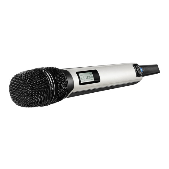
Product overview GZL 9000 antenna cable GZL cable, available in lengths of 5 m, N-type socket 10 m and 20 m N-type connector SKM 9000/SKM 9000 COM radio microphone A SET Microphone head button B ON/OFF Contacts of microphone head... - Page 21 Transmission mode display: when used with the BA 60 “HD” (High Definition Audio) or accupack) “LR” (Long Range Audio) Frequency/channel/name display, switchable Recommended microphone heads for the SKM 9000 radio microphone Microphone head Pick-up pattern Transducer principle ME 9002 omni-directional...
-
Page 22: Sk 9000 Bodypack Transmitter
7 SET 3-pin special audio socket button 8 UP button - Sennheiser microphones Catches - CI 1-4 Sennheiser instrument cable for accupack/battery pack - KA 9000 COM command adapter Snap-in elements 2 ON/OFF button for accupack/battery pack with ESC function (cancel) -
Page 23: Ka 9000 Com Command Adapter For The Sk 9000 Bodypack Transmitter
HSP 2 omni-directional HSP 4 cardioid Sennheiser CI 1-4 line/instrument cable ¼’’ (6.3 mm) jack plug (silent plug) to 3-pin special audio connector KA 9000 COM command adapter for the SK 9000 bodypack transmitter 3-pin special audio connector 3-pin special audio socket COMMAND button Connection cable, length: 1.6 m... -
Page 24: Ba 60 Accupack
Product overview BA 60 accupack Charging and data contacts Antenna Snap-in elements BA 61 accupack Snap-in elements Guide rail Charging and data contacts Digital 9000 | 23... -
Page 25: B 60 Battery Pack
Product overview B 60 battery pack Battery compartment for Antenna 2 AA size batteries Data contacts Snap-in elements B 61 battery pack Snap-in elements Guide rail Data contacts Battery compartment for 3 AA size batteries Cover 24 | Digital 9000... -
Page 26: L 60 Charger
Product overview L 60 charger Status LED Charging compartments for BA 60 or BA 61 accupacks DC input socket for connection of NT 3-1 mains unit Ventilation openings Rails for cascading up to 4 chargers Indications of the status LED Status LED 1 Meaning Standby mode/no connection to the mains Accupack is being charged,... -
Page 27: Preparing The Digital 9000 System For Use
MKE 2 CI 1-4 Preparing the EM 9046 receiver for use ......27 Preparing the SKM 9000 radio Setting up the receiver or mounting it into a 19” rack ..27 microphone for use ............35 Connecting devices to the analog audio outputs ....28 Changing the microphone head .......... -
Page 28: Preparing The Em 9046 Receiver For Use
Preparing the Digital 9000 system for use Preparing the EM 9046 receiver for use Setting up the receiver or mounting it into a 19” rack Setting up the receiver on a flat surface CAUTION! Risk of staining of furniture surfaces! Furniture surfaces can be treated with varnish, polish or synthetics which might cause stains when they come into contact with other synthetics. -
Page 29: Connecting Devices To The Analog Audio Outputs
Preparing the Digital 9000 system for use To mount the receiver into a 19” rack: Mount rack rails that are designed to carry the total weight of the EM 9046. Slide the receiver onto the rack rails and screw it to the front of the rack using 2 screws per side (screws to be ordered separately). -
Page 30: Connecting Devices To The Digital Audio Outputs
RF reception. For the pin assignment of the XLR-3 and sub-D sockets of the EM 9046, refer to the chapter “Specifications” on page 106. Ready-made AES3 cables are available from Sennheiser (optional accessories). Daisy chaining receivers The EM 9046 receivers feature an integrated antenna splitter so that up to four receivers can be daisy chained. - Page 31 Preparing the Digital 9000 system for use Connect the RF OUT N-type sockets of the first receiver to the RF IN N-type sockets of an additional receiver. To do so, use the RF patch cables from the EM 9046 CAB cable set. EM9046 ANT A ANT B...
-
Page 32: Connecting External Word Clock Signals
LAN DOWN allowing you to connect additional EM 9046 or other network-compatible Sennheiser receivers in a network. All receivers in the network can be controlled via the Wireless Systems Manager (WSM) software. Connect the first EM 9046 to a PC/laptop. We recommend using a CAT5 Ethernet cable with crush-resistant Neutrik EtherCon connectors. -
Page 33: Connecting The Receiver To The Mains
Preparing the Digital 9000 system for use If you have daisy chained your receivers (see page 29): Connect the network sockets of the receivers in the order shown on page 30. EM9046 LAN UP LAN DOWN Connecting the receiver to the mains CAUTION! Damage to the device due to electric current! If you connect the receiver to an unsuitable power supply, this... -
Page 34: Connecting Headphones
Preparing the Digital 9000 system for use Connecting headphones EM9046 CAUTION Danger of hearing damage due to high sound pressure levels! The headphones connected to the headphone socket are capable of producing very high sound pressure levels, which can cause permanent hearing damage. -
Page 35: Preparing The A/Ab/Ad 9000 Antennas And/Or Antenna Boosters For Use
Preparing the Digital 9000 system for use Preparing the A/AB/AD 9000 antennas and/or antenna boosters for use Antennas and antenna boosters of the Digital 9000 series are available in two variants: A1–A8 and B1–B8. Select the booster variant (A1–A8 or B1–B8) whose frequency range matches that of your transmitters: Booster variant A1–A8... -
Page 36: Connecting The Receiving Antennas/Antenna Boosters
Preparing the Digital 9000 system for use Connecting the receiving antennas/antenna boosters Use GZL 9000 antenna cables. Sennheiser GZL 9000 antenna cables are available in lengths of 5 m, 10 m and 20 m. A/AB/AD 9000: Connect the RF out... - Page 37 Preparing the Digital 9000 system for use Inserting batteries into the B 60 battery pack Insert the batteries (see diagram). Observe correct polarity when insert- ing the batteries. Only insert high-quality AA size batteries (e.g. lithium or alkaline batteries) into the B 60 battery pack. Do not insert individual rechargeable batteries such as NiMH cells.
-
Page 38: Changing The Microphone Head
Preparing the Digital 9000 system for use Changing the microphone head CAUTION! Damage to the microphone head! If you touch contacts, they can become dirty or damaged. Do not touch the contacts of the radio microphone nor the contacts of the microphone head. - Page 39 Preparing the Digital 9000 system for use CAUTION! Damage to the bodypack transmitter and/or the accupack/battery pack! If you touch the following contacts, they can become dirty or damaged: • Contacts for supply voltage and data contacts of the bodypack transmitter •...
- Page 40 For an overview of suitable microphones, refer to the product over- view on page 22. Connect the 3-pin special audio connector of the Sennheiser microphone or the Sennheiser CI 1-4 line/instrument cable to the 3-pin special audio socket 1. Lock the connector by screwing down the coupling ring.
-
Page 41: Connecting The Antenna
KA 9000 COM to the 3-pin special audio socket of the SK 9000. Connect the 3-pin special audio connector of the Sennheiser microphone or the Sennheiser CI 1-4 line/instrument cable to the 3-pin special audio socket of the KA 9000 COM. 40 |... -
Page 42: Preparing The L 60 Charger For Use
Preparing the Digital 9000 system for use Preparing the L 60 charger for use Cascading several chargers Up to 4 L 60 charger can be cascaded together and can be powered by the NT 3-1 mains unit. Prepare the L 60 chargers: –... - Page 43 Preparing the Digital 9000 system for use To fix the charger securely in place: Fix the charger by screwing screws (fillister head self-tapping screws as per DIN 7049, ST 3.5 x 32) through the four holes at the bottom of the charger.
-
Page 44: Using The Em 9046
Overview of the “ch” menu ..........65 “sys”, “ch”, “live” – operating modes at a glance ..45 Main menu “Channel setup” ..........67 Basic functions of the Sennheiser operating menu ..45 Extended menu “Transmitter setup” .......71 Displays of the Sennheiser operating menu ....46 Error and warning messages ..........48... -
Page 45: Switching The Receiver On/Off
The receiver’s operating system is loaded. During loading, the LED of the standby button flashes red and the display panel shows the Sennheiser start screen. Once the operating system is fully loaded, the receiver is in “live” oper- ating mode. -
Page 46: Sys", "Ch", "Live" - Operating Modes At A Glance
“sys” operating mode can be found from page 49 onwards. Basic functions of the Sennheiser operating menu A special feature of the Sennheiser 9000 series is the straightforward, intuitive operating concept. As a result, you can act quickly and precisely –... -
Page 47: Displays Of The Sennheiser Operating Menu
“live” operating mode. Displays of the Sennheiser operating menu The Sennheiser operating menu consists of the menu selection in the upper part, where you can select and call up menu items, and the... - Page 48 Using the EM 9046 If you call up a menu item by pressing the jog dial G, the menu selection is framed in blue: Menu item selected Audio output level output level Menu item called up Audio output level output level When a menu item has only a few options to choose from, this can be done directly via the menu selection (see for example the “word...
-
Page 49: Error And Warning Messages
Using the EM 9046 Error and warning messages Error and warning messages are displayed in white letters. The display panel is highlighted in orange. Example: “Frequency out of booster range” warning message Frequency out of booster range button L. In You can hide error/warning messages by pressing the order to check if errors or warnings are still present, you can call up the “System... -
Page 50: Sys" Operating Mode - Configuring The System
Using the EM 9046 “sys” operating mode – Configuring the system In “sys” operating mode, you can configure the transmitters and the receiver. Overview of the “sys” menu Main menu “System setup” Page Frequency scan Performs a frequency scan Audio output level Adjusts the output level Word clock Configures the word clock Cable attn... -
Page 51: Main Menu "System Setup
Using the EM 9046 Main menu “System setup” To get into the main menu: Select the “sys” operating mode. In the main menu, you can adjust the following settings: “Frequency scan” – Performing a frequency scan Frequency scan freq scan During the frequency scan, the interference levels received by the anten- nas are recorded and displayed for the booster frequency ranges 1 to 8. - Page 52 Range)”: Transmission of an audio signal whose bit rate is reduced – before transmission – by an audio data compression tech- nique (SeDAC, Sennheiser Digital Audio Codec). This compression tech- nique provides excellent audio quality and a large transmission range.
- Page 53 Using the EM 9046 Let us assume that you want to set up 8 transmission links and transmit in “HD” transmission mode with the maximum possible transmission range. Have a look at interference zone “HD” (see also above diagram): All booster frequency ranges except for B6 provide a sufficient number of unused frequency presets.
- Page 54 Using the EM 9046 Switch to the enlarged view of the activated booster frequency range by pressing the jog dial again after activation: Numeric please select booster range B8.19 Preset Freq measured Range: 774 - 798 MHz freq scan values Name: „CH1“...
- Page 55 Using the EM 9046 To configure your transmitters: Change to the “ch” operating mode on the EM 9046 (see page 65). Select one of the channels for which you have stored frequency presets. Call up the extended menu “Transmitter setup” and then call up the “RF mode”...
- Page 56 Using the EM 9046 Adjust the level. The setting becomes effective immediately. Press the jog dial to confirm your setting and to return to the channel selection. Adjust the level of further channels. button F. Your settings are stored and the receiver then Press the switches to the main menu.
- Page 57 Using the EM 9046 “Load config” – Loading a configuration defaults modified load config “load config” menu item allows you to load up to 10 saved settings of your system configuration (see also the “save config” menu item). In addition, you can ... •...
-
Page 58: Extended Menu "Service Setup
Using the EM 9046 “Network” – Configuring the network Name EM 9046 IPv4 address 169.254.92.238 network Slot analog: EM 9046 IPv4 address: auto 192.254.95.238 subnet mask: auto 255.255.0.0 gateway: auto 0.0.0.0 LAN UP: 00:1b:66:fe:c4:42 LAN DOWN: aa:1b:66:fe:c4:43 Via the “Network” menu item, you can assign the receiver a network name and select whether to obtain an IP address automatically or to enter the IP address manually. - Page 59 Using the EM 9046 In the extended menu, you can adjust the following settings: “Factory reset” – Resetting the receiver to the factory defaults Factory reset factory reset Via the “factory reset” menu item, you can reset your receiver to the fac- tory default settings.
- Page 60 Using the EM 9046 • In addition, all configurations saved in the “save config” menu item are deleted. • The event log is deleted and then the deleting itself is logged. The following settings/values are deleted: • time and date settings of the “Date &...
- Page 61 Using the EM 9046 “Logfile” – Displaying the event logs Logfile The EM 9046 receiver logs user actions and erroneous and suspicious sys- tem states. The log records the last 1000 events. The log entries contain the following information: • Time stamp (format “YYYY-MM-DD hh:mm:ss”) •...
- Page 62 Using the EM 9046 The menu selection changes its appearance when a warning message is present: Error/warning messages are present System check: system check No error/warning messages are present System check: system check Call up this menu item to get detailed information on error and warning messages.
- Page 63 Using the EM 9046 If, for example, a DAO module has been removed, the following warning message appears: Modules missing button L, the miss- If you hide this warning message by pressing the ing module is displayed in the “hw setup”...
- Page 64 Using the EM 9046 “Firmware” – Displaying the hardware versions/firmware versions and updating the firmware EM9046_2_3_1_12345 firmware Antenna booster Transmitter Update to firmware: 10-11-30-11 Start update SCAN MODE RF IN A: AB9000_2 Transmitter: Firmware: 10-08-10-10 Firmware: RF IN B: AB9000_2 New firmware Firmware: 10-08-10-10...
- Page 65 Using the EM 9046 Press the jog dial. The infra-red interface is activated and flashes blue, the “Start update” menu entry is highlighted in blue: Antenna booster Transmitter Update to firmware: 10-11-30-11 Start update SCAN MODE RF IN A: AB9000_2 Transmitter: Firmware: 10-08-10-10...
-
Page 66: Ch" Operating Mode - Configuring Channels
Using the EM 9046 “ch” operating mode – Configuring channels In “ch” operating mode, you can configure channels. Some of the settings that can be made can be synchronized via infra-red between the receiver and the transmitters. These settings are marked with a in the column (see also next page). - Page 67 Using the EM 9046 To synchronize the settings with your transmitters via infra-red: Select one of the channels 1–8. Switch on the transmitter to which you want to assign this channel. Press the button on the EM 9046. The receiver switches to synchronization mode and the flashes.
-
Page 68: Main Menu "Channel Setup
Using the EM 9046 Main menu “Channel setup” To get into the main menu: Select the “ch” operating mode. Select one or several channels (see page 46). Call up the menu items described in the following and adjust your settings. If no channel is selected, “Please select Channel”... - Page 69 You can use the command function e.g. for stage directions. For this, you require the SKM 9000 COM radio microphone or the SK 9000 bodypack transmitter together with the KA 9000 COM command adapter. By pressing the COMMAND button on the SKM 9000 COM or KA 9000 COM, you can influence the routing of the audio signal of the receiver’s XLR-3...
- Page 70 (XLR-3 sockets 1 ... 8) and the corresponding channel of the sub-D socket D. Pressing the COMMAND button on the SKM 9000 COM or KA 9000 COM has no effect. “add” The transmitter’s audio signal is output via its audio channel (XLR-3 sockets 1 ...
- Page 71 M. the channels by pressing one of the channel - If you are using an SKM 9000 COM or an SK 9000 together with the KA 9000 COM command adapter, you can set markers by pressing the COMMAND button at critical locations.
-
Page 72: Extended Menu "Transmitter Setup
(frequency range, type of microphone head being used (SKM), type of Sennheiser microphone or cable being used (SK), etc.). If you adjust settings that are not supported by the transmitters’ current... - Page 73 Range)”: Transmission of an audio signal whose bit rate is redu- ced – before transmission – by an audio data compression technique (SeDAC, Sennheiser Digital Audio Codec). This compression technique pro- vides excellent audio quality and a large transmission range. The sensiti- vity to interference is reduced compared to “HD”...
- Page 74 Using the EM 9046 “Display” – Selecting the standard display for the transmitters frequency display The “Display” menu item allows you to activate one out of 3 standard dis- plays: “Name”, “Preset” or “Frequency”. The “Name” standard display is factory preset. “Lock”...
-
Page 75: Live" Operating Mode - Using A Configured System
Using the EM 9046 “live” operating mode – Using a configured system In “live” operating mode, you can select channels for headphone monitor- ing and synchronize the transmitters and the receiver. To prepare headphone monitoring: Connect headphones as described on page 33. Observe the warnings given there. -
Page 76: Using The Skm 9000
Using the SKM 9000 Using the SKM 9000 Using the SKM 9000 .............. 75 Basic functions of the Sennheiser operating menu ..78 Switching the SKM 9000 on/off ........76 Overview of the status displays ........78 Activating/deactivating the automatic lock mode Overview of the menu items .......... -
Page 77: Switching The Skm 9000 On/Off
Switching the SKM 9000 on/off When the SKM 9000 is switched on for the first time, it contains the first frequency preset of the transmitter frequency range (e.g. A1.1: 470.200 MHz). Via the “ch” menu of the EM 9046 receiver, set the... -
Page 78: Activating/Deactivating The Automatic Lock Mode (Autolock)
Using the SKM 9000 To check the set frequency/the selected frequency preset: Call up the operating menu and press the button /DOWN button until the “Tune” or “Preset” menu item appears. The set frequency/the selected frequency preset is displayed. If the displayed value is the desired one: Wait for 10 seconds to pass. -
Page 79: Basic Functions Of The Sennheiser Operating Menu
Basic functions of the Sennheiser operating menu A special feature of the Sennheiser 9000 series is the straightforward, intuitive operating concept. As a result, you can act quickly and precisely – even in stressful situations, for example on stage or during a live show or presentation. -
Page 80: Overview Of The Menu Items
Using the SKM 9000 Overview of the menu items Icon Name Function Page Tune Sets a frequency Preset Selects a frequency preset Name Enters a name Gain Adjusts the input gain Low cut Sets the low-cut filter RF mode Adjusts the transmission mode... - Page 81 Using the SKM 9000 “Name” – Entering a name Via the “Name” menu item, you can enter a freely selectable name for the radio microphone. The name can consist of up to 6 characters from the fol- lowing character set: `+` `,` `-` `|` `/` `0` `1` `2` `3` `4` `5` `6` `7` `8` `9` `*` `;` `<` `=` `>`...
-
Page 82: Using The Sk 9000
Using the SK 9000 Using the SK 9000 Using the SK 9000 ..............81 Basic functions of the Sennheiser operating menu ..84 Switching the SK 9000 on/off ..........82 Overview of the status displays ........84 Activating/deactivating the automatic lock mode Overview of the menu items .......... -
Page 83: Switching The Sk 9000 On/Off
To switch the SK 9000 on: Keep the ON/OFF button pressed until the Sennheiser logo appears on the display panel C. lights up and the standard display (here: “Frequency”, see page 86) appears on the display panel C. The bodypack transmitter transmits an RF signal and the transmission mode display “HD”/“LR”... -
Page 84: Activating/Deactivating The Automatic Lock Mode (Autolock)
Using the SK 9000 To check the set frequency/the selected frequency preset: Call up the operating menu and press the button /DOWN button until the “Tune” or “Preset” menu item appears. The set frequency/the selected frequency preset is displayed. If the displayed value is the desired one: Wait for 10 seconds to pass. -
Page 85: Basic Functions Of The Sennheiser Operating Menu
Basic functions of the Sennheiser operating menu A special feature of the Sennheiser 9000 series is the straightforward, intuitive operating concept. As a result, you can act quickly and precisely – even in stressful situations, for example on stage or during a live show or presentation. -
Page 86: Overview Of The Menu Items
Information Displays the firmware version and frequency range a. If you are using the Sennheiser CI 1-4 line/instrument cable, this menu item is hidden If you are using the Sennheiser CI 1-4 line/instrument cable, this menu item is shown “Tune”–... - Page 87 “Cable” – Emulating different instrument cable lengths Via the “Cable” menu item, you can emulate the lengths of instrument cables in 3 steps. If you are using the Sennheiser CI 1-4 line/Instrument cable, the “Cable” menu item is shown. “RF mode” - Adjusting the transmission mode “RF...
- Page 88 Using the SK 9000 “Lock” – Activating/deactivating the lock mode Via the “Lock” menu item, you can activate or deactivate the lock mode. For more information on how to activate or deactivate the lock mode, refer to page 83. “Test tone” – Activating the 1 kHz test tone Via the “Test tone”...
-
Page 89: Using The L 60
Digital 9000 Using the L 60 Using the L 60... - Page 90 Using the L 60 Using the L 60 Connecting the mains unit and switching on the L 60 Connect the DC connector of the NT 3-1 mains unit to the DC input socket of the L 60 charger. Connect the mains plug (EU, UK or US version) of the mains unit to the mains.
- Page 91 Using the L 60 The accupack is being charged. The status LED lights up. It is normal for the accupack to get warm during charging. For an overview of the indications of the status LED 1, refer to page 25. Charging times With a completely discharged accupack and at room temperature (approx.
-
Page 92: Cleaning And Maintaining The Digital 9000 System
Cleaning and maintaining the Digital 9000 system Digital 9000 Cleaning and maintenance Cleaning and maintaining the Digital 9000 system Digital 9000 | 91... - Page 93 Cleaning and maintaining the Digital 9000 system Cleaning and maintaining the Digital 9000 system CAUTION Liquids can damage the electronics of the products! Liquids entering the housing of the products can cause a short-circuit and damage the electronics. Keep all liquids away from the products. Do not use any solvents or cleansing agents.
- Page 94 Cleaning and maintaining the Digital 9000 system Cleaning the contacts of the SK 9000 bodypack transmitter Wipe the contacts with a dry cloth. Cleaning the L 60 charger Remove all accupacks from the charging compartments. Before cleaning, disconnect the NT 3-1 mains unit from the mains. Use a dry cloth for cleaning.
-
Page 95: If A Problem Occurs
Cleaning and maintaining the Digital 9000 system Digital 9000 If a problem occurs ... 94 | Digital 9000... -
Page 96: Em 9046 Receiver
Cleaning and maintaining the Digital 9000 system If a problem occurs ... EM 9046 receiver Problem Possible cause Possible solution No mains connection, Check the connections of the ON/OFF 1 ON/OFF 1 operation switch is mains cable. Set the indication set to position “0”... -
Page 97: Skm 9000 Radio Microphone
Cleaning and maintaining the Digital 9000 system SKM 9000 radio microphone Problem Possible cause Possible solution Transmitter cannot Lock mode is Deactivate the lock mode be operated, activated (see page 80) “LOCK” appears on the display panel No operation Batteries are flat or... -
Page 98: L 60 Charger
If a problem occurs that is not listed in the above table or if the problem cannot be solved with the proposed solutions, please contact your local Sennheiser partner for assistance. To find a Sennheiser partner in your country, search at www.sennheiser.com under “Service & Support”. Digital 9000... -
Page 99: Specifications
Cleaning and maintaining the Digital 9000 system Digital 9000 Specifications 98 | Digital 9000... - Page 100 Audio frequency response 30 Hz to 20 kHz (3 dB) with SK 9000 line-in 60 Hz to 20 kHz (3 dB) with SK 9000 mic 80 Hz to 20 kHz (3 dB) with SKM 9000 Dynamic range “HD” mode: 112 dB(A) “LR”...
- Page 101 Cleaning and maintaining the Digital 9000 system Operating conditions Ambient temperature -10°C to +50°C Relative humidity max. 85% at 40°C (non-condensing) Protection against dripping and light splashing of liquids the product must not be exposed to dripping and splashing (IP2X) Storage and transport conditions Ambient temperature -25°C to +70°C...
- Page 102 Cleaning and maintaining the Digital 9000 system Booster supply 12 V DC via antenna socket max. 200 mA each, short-circuit proof IEEE 802.3-2002 (10/100 Mbit/s), shielded RJ 45 socket BNC, 75 , transformer balanced, AC-coupled Word clock input input voltage range: 200 mV … 5 Vpp max.
- Page 103 Cleaning and maintaining the Digital 9000 system Other characteristics Current consumption max. 160 mA at 12 V Voltage range 9 to 18 V DC feed via antenna cable from EM 9046 Mounting connection 3/7” or 5/7” thread Dimensions A 9000: 250 x 165 x 23 mm (H x W x D) AB 9000: 80 x 64 x 24 mm (H x W x D)
- Page 104 SKM 9000 characteristics RF characteristics Frequency ranges 470 MHz to 798 MHz, divided into 4 ranges: SKM 9000 A1–A4: 470–558 MHz SKM 9000 A5–A8: 550–638 MHz SKM 9000 B1–B4: 630–718 MHz SKM 9000 B5–B8: 710–798 MHz (see page 99) Switching bandwidth...
- Page 105 Cleaning and maintaining the Digital 9000 system Audio characteristics Audio gain adjustable in 3 dB steps from 0 dB to +62 dB (depending on microphone head) Lower cut-off frequency (–3 dB) adjustable: 80 Hz, 100 Hz, 120 Hz Other characteristics Operating time 5.5 hrs (with BA 60 accupack) Power consumption...
- Page 106 • Deep discharge recovery charge • Capacity monitoring • Accupack temperature monitoring • Over/undercharge detection • Charging time limit (approx. 8 hours) Compatible Sennheiser • BA 60 (3.7 V, 1,600 mAh, Li-Ion) accupacks • BA 61 (3.7 V, 2,030 mAh, Li-Ion) Charging time with a completely discharged accupack and at room temperature (approx.
- Page 107 Cleaning and maintaining the Digital 9000 system Pin assignment of the sockets of the EM 9046 XLR-3 socket (analog & digital) Pin assignment Pin 1: ground Pin 2: out + (P) Pin 3: out (N) Sub-D socket (25-pin) multicore, digital, balanced open open CH7/8P...
-
Page 108: Manufacturer Declarations
Manufacturer Declarations Manufacturer Declarations Warranty Sennheiser electronic GmbH & Co. KG gives a warranty of 24 months on this product. For the current warranty conditions, please visit our web site at www.sennheiser.com or contact your Sennheiser partner. In compliance with the following requirements •... - Page 109 Sennheiser electronic GmbH & Co. KG Am Labor 1, 30900 Wedemark, Germany www.sennheiser.com Publ. 07/12...
Need help?
Do you have a question about the SKM 9000 and is the answer not in the manual?
Questions and answers