Sennheiser freePORT Systems Manual
- Instructions for use manual (20 pages) ,
- Instructions for use manual (16 pages) ,
- Instructions for use manual (56 pages)
Advertisement
- 1 Important safety instructions
- 2 The freePORT systems
- 3 Delivery includes
- 4 EM 1 receiver
- 5 SK 2 bodypack transmitter
- 6 SKM 3 radio microphone
- 7 Setting up the system
- 8 Care and maintenance
- 9 If problems occur...
- 10 Accessories and variants
- 11 Specifications of the freePORT systems
- 12 Documents / Resources
Important safety instructions
- Read this instruction manual.
- Keep this instruction manual in a safe place. Always include this instruction manual when passing the device and the mains unit on to third parties.
- Heed all warnings and follow all instructions.
- Clean the device and the mains unit only with a dry cloth.
- Refer all servicing to qualified service personnel. Servicing is required if the device or the mains unit has been damaged in any way, liquid has been spilled, objects have fallen inside, the device or the mains unit has been exposed to rain or moisture, does not operate properly or has been dropped.
![]()
To reduce the risk of fire or electric shock, do not expose the device and the mains unit to rain or moisture. Do not place objects filled with liquids, such as vases or coffee cups, on the device.- Only use the supplied mains unit.
- Disconnect the mains connector from the wall socket
- to completely disconnect the device from the mains,
- during lightning storms or when unused for long periods of time.
- The mains unit must be operated only from the type of power source specified in the chapter "Specifications of the freePORT systems".
- Ensure that the mains unit is
- always readily operable and easily accessible,
- properly plugged into the wall socket,
- only operated within the permissible temperature range,
- not covered or exposed to direct sunlight for longer periods of time in order to prevent heat accumulation (see "Specifications of the freePORT systems").
- Do not block any ventilation openings. Install the device and the mains unit in accordance with the manufacturer's instructions.
- Do not install the device and the mains unit near any heat sources.
- Only use attachments/accessories specified by Sennheiser.

The freePORT systems
Designed for different areas of application, the freePORT systems are available in three variants.
- Presentation Set:
This system is ideal for presentation applications. The unobtrusive ME 2 clip-on microphone is virtually invisible. - Instrument Set:
This system is for connecting musical instruments (e.g. guitar) which have a ¼" (6.3 mm) jack socket directly to the bodypack transmitter. - Vocal Set:
This system is ideal for vocal and speech applications.
Transmitters and receivers of the freePORT systems have four factory-preset frequencies for direct channel selection – ready for immediate use after switch-on.
The freePORT systems are available in three UHF frequency ranges:
- Frequency range A: 719 to 721 MHz
- Frequency range B: 691 to 693 MHz
- Frequency range C: 742.5 to 744.5 MHz
- Frequency range E: 863 to 865 MHz
Notes:
Use of A, B and C frequency ranges must be licensed. Most EU countries do not require licensing for use of frequency range E. Frequency range B (691 to 693 MHz) is intended for use solely in the USA and Canada.
Please be legal and observe the country-specific regulations of the licensing authorities. Sennheiser are not responsible if you operate illegally.
To avoid interfering with other users, the transmitter should be switched off when not in use.
Features of the freePORT systems:
- Up to four transmission links per frequency range which can be operated simultaneously
- Reliable transmission technology
- Diversity technology for minimizing dropouts in the reception
- Adjustable squelch for eliminating RF interference
- Rugged housings
- Crystal-clear reception due to dynamic processor
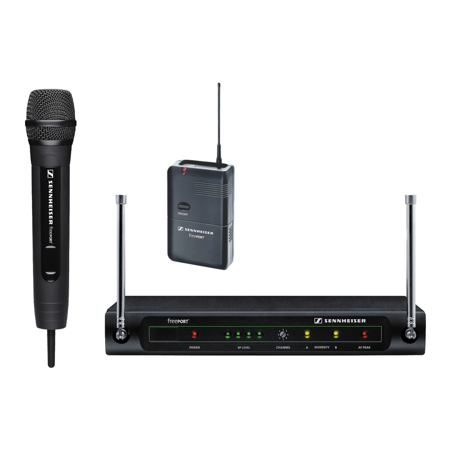
Delivery includes
| FreePORT systems | EM 1 receiver | SK 2 bodypack transmitter | SKM 3 radio microphone | Mains unit (NTxy) | ME 2 clip-on microphone | ¼" (6.3 mm) jack cable | Stand mount | Instructions for use |
| Presentation Set | X | X | X | X | X | |||
| Instrument Set | X | X | X | X | X | |||
| Vocal Set | X | X | X | X | X |
EM 1 receiver

Operating controls
- Antenna A
- Operation indication, green LED (POWER)
- RF level indication, four green LEDs (RF LEVEL)
- Channel selector switch CHANNEL (1 to 4)
- Diversity indication, yellow LED A (lights up if antenna
![]() is active)
is active) - Diversity indication, yellow LED B (lights up if antenna
![]() is active)
is active) - AF PEAK, red LED (lights up if the audio level is too high)
- Antenna B
- Audio output, XLR-3M socket, balanced (AUDIO OUTPUT XLR BAL)
- Audio output, ¼" (6.3 mm) jack socket, unbalanced (AUDIO OUTPUT UNBAL)
- Audio output level control (GAIN)
- Squelch threshold control (SQUELCH)
- DC socket for connection of mains unit (DC 11–18 V IN, 100 mA)
- Type plate
- Serial number
 is active)
 is active)
Connecting the receiver
- Insert the DC connector on the mains cable into the DC socket
![]() and connect it to the mains. The green LED for operation indication (POWER)
and connect it to the mains. The green LED for operation indication (POWER) ![]() lights up and the receiver is ready for operation.
lights up and the receiver is ready for operation. - To deactivate the receiver, remove the mains plug from the mains outlet.
 and connect it to the mains. The green LED for operation indication (POWER)
  lights up and the receiver is ready for operation.
Aligning the antennas
- Set up the antennas and align them upwards in a V-shape.
The LEDs A and B indicate which diversity section (i.e. which antenna) is active.
Connecting the amplifier/mixing console
- Connect the amplifier/mixing console to the XLR-3M socket
![]() or the ¼" (6.3 mm) jack socket
or the ¼" (6.3 mm) jack socket ![]() .
. - Use the GAIN control
![]() to adapt the level of the audio output to the input of the amplifier or mixing console. The adjusted audio output level is common for both sockets. If the level is adjusted too high, the audio signal will be distorted. If, on the other hand, the level is adjusted too low, this will result in an audio signal with high background noise.
to adapt the level of the audio output to the input of the amplifier or mixing console. The adjusted audio output level is common for both sockets. If the level is adjusted too high, the audio signal will be distorted. If, on the other hand, the level is adjusted too low, this will result in an audio signal with high background noise.
 .
. to adapt the level of the audio output to the input of the amplifier or mixing console. The adjusted audio output level is common for both sockets. If the level is adjusted too high, the audio signal will be distorted. If, on the other hand, the level is adjusted too low, this will result in an audio signal with high background noise.
Selecting and changing a channel
You can change the channel on the receiver during running operation. The receiver then immediately receives on the new channel.
- Use a small screwdriver to set the channel selector switch
![]() to the desired channel. You can switch between four different channels ("Selecting a channel").
to the desired channel. You can switch between four different channels ("Selecting a channel").
 to the desired channel. You can switch between four different channels ("Selecting a channel").
SK 2 bodypack transmitter

Operating controls
- ON/OFF button
- Operation and battery status indication, red LED
- Microphone/instrument input, 3.5 mm jack socket (lockable)
- Antenna (can be screwed off)
- Battery compartment cover
- MIC/INST slide switch
- Serial number
- Channel selector switch CH (1 to 4)
- Sensitivity control GAIN
- Type plate
- Belt clip
Inserting/replacing the battery
We recommend powering the bodypack transmitter by a 9 V PP3 alkaline battery (IEC 6 LR 61). If powered by a rechargeable 9 V battery, the operating time will be drastically reduced.

- Open the battery compartment by first sliding the battery compartment cover in the direction of the arrow. Then flip the battery compartment cover open.
- Insert the battery as shown. Please observe correct polarity when inserting the battery.
- Close the battery compartment.
Note:
When the red LED  goes off during operation, you must replace the battery as soon as possible.
Connecting the microphone/instrument cable
The audio input is designed for the connection of both the ME 2 clip-on microphone and instruments (e.g. guitars).
- Connect the 3.5 mm jack plug from the microphone/instrument cable to the 3.5 mm jack socket
![]() .
. - Check the setting of the MIC/INST slide switch
![]() which allows you to switch between microphone and instrument operation. If necessary, readjust the setting.
which allows you to switch between microphone and instrument operation. If necessary, readjust the setting. - Use the GAIN control
![]() to adjust the transmitter sensitivity so that the receiver receives a good audio signal (no distortion and no background noise).
to adjust the transmitter sensitivity so that the receiver receives a good audio signal (no distortion and no background noise).
Attaching and positioning the microphone

Use the microphone clip to attach the ME 2 clip-on microphone to clothing (e.g. tie, lapel). Conduct the microphone cable so that noise due to friction is avoided and make sure that the antenna and the cable do not cross. The omni-directional microphone picks up sound equally from all directions. However, it should be attached as close as possible to the sound source.
Attaching the bodypack transmitter to clothing
- Use the supplied belt clip
![]() to attach the bodypack transmitter to clothing. Make sure that the antenna is at least 1 cm away from the body and is not kinked.
to attach the bodypack transmitter to clothing. Make sure that the antenna is at least 1 cm away from the body and is not kinked.
Switching the bodypack transmitter on/off
- Press the ON/OFF button
![]() to switch the bodypack transmitter on or off. If the bodypack transmitter is switched on, the red LED
to switch the bodypack transmitter on or off. If the bodypack transmitter is switched on, the red LED ![]() lights up.
lights up.
Note:
Remove the battery when the transmitter will not be used for extended periods of time.
Selecting and changing a channel
- Switch off the transmitter before you change the channel.
- Use a small screwdriver to set the channel selector switch
![]() to the desired channel. You can switch between four different channels. When you switch on the bodypack transmitter again, it will transmit on the new channel ("Selecting a channel").
to the desired channel. You can switch between four different channels. When you switch on the bodypack transmitter again, it will transmit on the new channel ("Selecting a channel").
 to the desired channel. You can switch between four different channels. When you switch on the bodypack transmitter again, it will transmit on the new channel ("Selecting a channel").
SKM 3 radio microphone

Operating control
- Sound inlet basket
- Locking ring of battery compartment
- Body of radio microphone
- Battery compartment (not visible from outside)
- Antenna (can be screwed off)
- Operation and battery status indication, red LED (POWER)
- ON/OFF switch
- Channel selector switch CH (1 to 4)
- Type plate
- Serial number
Note:
The microphone head of the radio microphone cannot be changed.
Inserting/replacing the battery
We recommend powering the radio microphone by a 9 V PP3 alkaline battery (IEC 6 LR 61). If powered by a rechargeable 9 V battery, the operating time will be drastically reduced.

- Turn the locking ring of the battery compartment
![]() in the direction of the arrow.
in the direction of the arrow. - Pull the body of the radio microphone
![]() in the direction of the arrow as far as it will go.
in the direction of the arrow as far as it will go. - Insert the battery as shown. Please observe correct polarity when inserting the battery.
- Close and lock the radio microphone.
Note:
When the red LED  goes off during operation, you must replace the battery as soon as possible.
Switching the radio microphone on/off
- Use the ON/OFF switch
![]() to switch the radio microphone on or off. If the radio microphone is switched on, the red LED
to switch the radio microphone on or off. If the radio microphone is switched on, the red LED ![]() lights up.
lights up.
 to switch the radio microphone on or off. If the radio microphone is switched on, the red LED
 Note:
Remove the battery when the transmitter will not be used for extended periods of time.
Selecting and changing a channel
- Switch off the radio microphone.
- Open the radio microphone ("Inserting/replacing the battery").
- Use a small screwdriver to set the channel selector switch
![]() to the desired channel. You can switch between four different channels ("Selecting a channel").
to the desired channel. You can switch between four different channels ("Selecting a channel"). - Close and lock the radio microphone.
- Switch on the radio microphone again.
Sensitivity of the radio microphone
You can vary the bass reproduction by increasing/decreasing the talking distance.
Setting up the system
Before starting transmission, do a soundcheck and set up the system as follows:
Setting up the reception

The receiver's four LEDs (RF LEVEL)  indicate the level of the received RF signal. With the transmitter, walk up and down the transmission area and check if the received RF signal is sufficient everywhere. Reception is good if all four LEDs light up. Please observe the following:
- Transmission range depends to a large extent on location and can be up to 100 m. Observe a minimum distance of 3 m between transmitter and receiver. There should be a "free line of sight" between transmitting and receiving antennas.
- Do not operate the system close to metal objects such as cross members or reinforced-concrete walls. Computers or mobile phones in direct proximity to the antenna will interfere with the reception.
- Each transmitter requires a receiver. When using several transmission links simultaneously, make sure that all transmission links operate on different channels.
Adjusting the squelch threshold
Interference due to other transmission links can be eliminated as follows:
- Switch off the transmitter. The receiver should no longer receive a signal.
- If the receiver still receives a signal, use the SQUELCH control
![]() to increase the squelch threshold so that the signal will no longer be received. If the signal cannot be eliminated in this way, set the transmitter and the receiver to a different channel.
to increase the squelch threshold so that the signal will no longer be received. If the signal cannot be eliminated in this way, set the transmitter and the receiver to a different channel.
![]()
- Switch on the transmitter again and check if the receiver receives the transmitter signal.
 to increase the squelch threshold so that the signal will no longer be received. If the signal cannot be eliminated in this way, set the transmitter and the receiver to a different channel.
Note:
If the squelch threshold is adjusted too high, the transmission range will be reduced. Therefore, always adjust the squelch threshold to the lowest possible setting.
Selecting a channel
Transmitters and receivers have four channels respectively with intermodulation-free frequencies.
Note:
These frequencies are different to those in evolution systems and freePORT systems should not be used together with evolution systems without great care.
- Always set the transmitter and the receiver to the same channel.
Adjusting the transmitter sensitivity
- Use the GAIN control
![]() on the SK 2 bodypack transmitter to adjust the sensitivity so that even during the loudest passages the AF PEAK LED
on the SK 2 bodypack transmitter to adjust the sensitivity so that even during the loudest passages the AF PEAK LED ![]() on the EM 1 receiver does not light up.
on the EM 1 receiver does not light up.
![]()

Care and maintenance
Use a slightly damp cloth to clean the units from time to time.
Note:
Do not use any cleansing agents or solvents.
To clean the SKM 3's sound inlet basket:
- Unscrew the sound inlet basket
![]() (turn counterclockwise) and remove it.
(turn counterclockwise) and remove it.
![]()
- Remove the foam insert and use a slightly damp cloth to clean the sound inlet basket.
- Reinsert the dry foam insert, replace the sound inlet basket on the SKM 3 and screw it tight.

If problems occur...
| Problem | Possible cause | Possible solution |
| No operation indication | Battery is flat | Replace the battery |
| No mains connection (receiver) | Check the connections of the mains unit | |
| No RF signal | Transmitter and receiver are not on the same channel | Set transmitter and receiver to the same channel |
| Transmitter is out of range | Reduce the distance between transmitter and receiver | |
| RF signal available, no audio signal | Receiver's squelch threshold is adjusted too high | See "Adjusting the squelch threshold" |
| Audio signal has a high level of background noise or is distorted | Transmitter sensitivity is adjusted too low or too high | See "Connecting the microphone/ instrument cable" |
| The MIC/INST slide switch on the SK 2 transmitter is not set correctly | ||
| Receiver's audio output level is adjusted too low or too high | See "Connecting the amplifier/ mixing console" | |
| Annoying noises | When the battery is almost flat, the transmitter may produce annoying noises which can damage the PA system. | After the LED has gone off, replace the battery as soon as possible or switch the transmitter off. |
Accessories and variants
| 04839 | MZW 1 | Wind- and popshield for SKM 3 |
| 76670 | MZQ 1 | Microphone clamp for SKM 3 |
| 05018 | ME 2 | Clip-on microphone for SK 2, pre-polarized condenser microphone, omnidirectional |
| 05019 | ME 3 | Headmic for SK 2, pre-polarized condenser microphone, super-cardioid |
| 05020 | ME 4 | Clip-on microphone for SK 2, pre-polarized condenser microphone, cardioid |
| 512889 | CI1-fp | Guitar cable |
Specifications of the freePORT systems
System characteristics
| Transmission/receiving frequencies | 4 UHF transmission/receiving frequencies Range A: 719 to 721 MHz (719.15 – 719.75 – 720.15 – 720.85 MHz) Range B: 691 to 693 MHz (691.00 – 691.40 – 692.35 – 692.90 MHz) Range C: 742.5 to 744.5 MHz (742.65 – 743.35 – 743.85 – 744.45 MHz) Range E: 863 to 865 MHz (863.10 – 863.70 – 864.10 – 864.90 MHz) |
| Switching bandwidth | 2 MHz |
| Signal-to-noise ratio | > 95 dB(A) |
| THD (1 kHz) | < 1 % |
| Temperature range | –10 bis +45°C / 95 relative humidity |
Individual components
| EM 1 receiver | SK 2 bodypack transmitter | SKM 3 radio microphone | |
| Power supply | 12V DCNOM /100 mA | 9 V PP3 battery | 9 V PP3 battery |
| Operating time (with alkaline battery) | – | approx. 10 hrs | approx. 10 hrs |
| Frequency response | – | 60...16,000 Hz ± 3 dB | 80...16,000 Hz ± 3 dB |
| RF output power (-3 dB) | – | 10 mW | 10 mW |
| AF output voltage | – | – | |
| ¼'' (6.3 mm) jack socket (unbal.): | max. +10 dBu | ||
| XLR socket (balanced): | max. +16 dBu | ||
| Dimensions in mm | approx. 35 x 213 x 98 | approx. 60 x 100 x 30 (with belt clip) | approx. 285; ∅ approx. 35 x 50 |
| Weight | approx. 570 g | approx. 90 g | approx. 210 g |
| Transducer principle | – | – | dynamic |
| Pick-up pattern | – | – | cardioid |
ME 2 clip-on microphone
| Transducer principle | pre-polarized condenser |
| Pick-up pattern | omni-directional |
Type approvals
| In compliance with |  | EMC | EN 301489-1/-9 |
| Radio | EN 301357-1/-2 | ||
| Safety | EN 60065 |
Also approved by
| Industry Canada | RSS 210, | IC: 2099A |
| SKM3/EM1-A/-C | IC: 2099A-FPSKMEM | |
| SKM3/EM1-B | IC: 2099A-FPSKMEMB | |
| SK2-A/-C | IC: 2099A-FPSK | |
| SK2-B | IC: 2099A-FPSKB | |
| FCC-Part 74 | SK2-A/-C | FCC ID: DMOB1FPXD |
| SK2-B | FCC ID: DMOB2FPSK | |
| SKM3-A/-C | FCC ID: DMOH1FPXD | |
| SKM3-B | FCC ID: DMOH2FPSKM |
Transmitters that operate in the frequency range E (863 – 865 MHz) can be used licence-free in the following countries:
AT, BA, BE, CH, CY, CZ, DE, DK, EE, ES, FI, FR, GB, GR, HU, IE, IS, IT, LI, LT, LU, ME, MK, MT, NL, NO, PL, PT, RO, RS, RU, SE, SI, SK, TR, UA.
Transmitters that operate in frequency range A (719 – 721 MHz), B (691–693 MHz) or frequency range C (742.5 – 744.5 MHz) must only be used with an appropriate radio transmission licence. Frequency range B is intended for use solely in the USA and Canada.
| Frequency range | Presentation Set | Instrument Set | Vocal Set |
| 691 – 693 MHz: with US mains unit | freePort fp 12-B-US | freePort fp 72-B-US | freePort fp 35-B-US |
| 719 – 721 MHz: with US mains unit | freePort fp 12-A-US | freePort fp 72-A-US | freePort fp 35-A-US |
| 742.5 – 744.5 MHz: with EU mains unit | freePort fp 12-C-EU | freePort fp 72-C-EU | freePort fp 35-C-EU |
| with US mains unit | freePort fp 12-C-US | freePort fp 72-C-US | freePort fp 35-C-US |
| 863 – 865 MHz: with EU mains unit | freePort fp 12-E-EU | freePort fp 72-E-EU | freePort fp 35-E-EU |
| with UK mains unit | freePort fp 12-E-UK | freePort fp 72-E-UK | freePort fp 35-E-UK |
Connector assignment
| EM 1: | EM 1: | EM 1: | EM 1: | SK 2: |
| ¼'' (6.3 mm) stereo jack plug, unbalanced | ¼'' (6.3 mm) mono jack plug, unbalanced | XLR-3F connector, balanced | DC connector for power supply | 3.5 mm jack plug |
 |  |  |  |  |

Documents / ResourcesDownload manual
Here you can download full pdf version of manual, it may contain additional safety instructions, warranty information, FCC rules, etc.
Advertisement


Need help?
Do you have a question about the freePORT and is the answer not in the manual?
Questions and answers