
Subscribe to Our Youtube Channel
Related Manuals for Meyra 2.750


Summary of Contents for Meyra 2.750
- Page 1 Lightweight wheelchairs Model 2.750 / 2.850 Operating manual W e m o v e p e o p l e .
-
Page 2: Table Of Contents
Contents Introduction List of models Indications Acceptance Specifications Adjustment Reinstallment Life span Overview Brake Pressure brake - user Locking the brakes Releasing the brakes Service brake Brake lever extension Drum brake for accompanying persons Function as operating brakes Activating/releasing the drum brakes Leg supports Calf belt Removing the calf belt... - Page 3 Leg support upper part Turning the leg supports to the side Swivelling in the leg supports Removing the leg supports Attaching the leg supports Mechanically height-adjustable leg supports Lifting/lowering the leg support Arm supports Removing the arm support Inserting the arm support Swivelling up the arm support Height adjustment of the arm support Back support...
- Page 4 Technical data Tyre pressure of pneumatic tyres Meaning of the labels on the wheelchair Meaning of the symbols on the type plate Inspection certificate Warranty / Guarantee Warrantee / Guarantee section Inspection certificate for transfer...
-
Page 5: Introduction
PDF-files of above mentioned documents on our website under: We thank you for the confidence you have placed in our company by choosing a < www.meyra.com >. wheelchair from this series. ☞ Contact your specialist dealer when re- With all equipment and their accessories quired. -
Page 6: List Of Models
This operating manual applies to the follow- The wheelchair of the lightweight-family, ing models: was developed for adults and adolescents. Model 2.750 The wheelchair solely serves to transport Model 2.850 one person in the seat and not as a hauling aid, transporter or similar. -
Page 7: Use
ADJUSTMENT The wheelchair is applicable on level, firm The specialist workshop will hand out the surfaces and can be used as follows: wheelchair to you under consideration of all relevant safety instructions, ready for opera- – for indoors (e.g. apartment, day care), tion and adjusted to your needs. -
Page 8: Reinstallment
REINSTALLMENT LIFE SPAN The wheelchair is suited for reinstallment. We expect an average life span of about With the building block system the wheel- 4 years for this product, as far as the product chair can be fit to accommodate different is applied for its designated purpose and all handicaps body sizes. -
Page 9: Overview
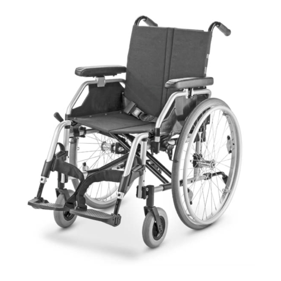
OVERVIEW The overview shows, representative for all models, the most important components of the wheelchair. Pos. Description (8) Steering wheel (1) Push handle (9) Driving wheel (2) Back support (10) Brake lever – pressure brake (3) Arm support (11) Handrims (4) Clothes guard (12) Locking knob –... -
Page 10: Brake
BRAKE By locking the brakes with the brake lever (1), the wheelchair is secured against rolling away unintentionally (parking brake). Depending on the version, the wheelchair can be equipped with pressure brakes (2) or with drum brakes (3). ☞ Note: Therefore observe the Maintenance schedule on page 31 as well as safe- ty and general handling instructions... -
Page 11: Brake Lever Extension
Brake lever extension The brake lever extensions multiply the ap- plied brake force and reduce the force you need to apply in order to lock the brakes (1). Attention: Do not use the grips of the brake lever as support! •... -
Page 12: Drum Brake For Accompanying Persons
Drum brake for accompanying persons The drum brake is activated by the accom- panying person through the brake levers [1]. Function as operating brakes Use both brake levers evenly and only light- ly in order to achieve a controlled decelera- tion of the wheelchair. -
Page 13: Leg Supports
LEG SUPPORTS Attention: Before any actions on the leg supports the wheelchair is to be secured against unintentional rolling motions. ☞ For this observe chapter Brake on page 10. Calf belt The removable calf belt (1) prevents the feet from sliding off the back of the footboard. Attention: Do not drive without the calf belt. -
Page 14: Lower Leg Support
Lower leg support The footplates, resp. footboard needs to be folded up before entry or exit [1]. ☞ Check the locking points! – Remove both feet from the footplates. – Remove the calf belt (2), if present. ☞ Therefore observe chapter Calf belt on page 13. -
Page 15: Leg Support Upper Part
Leg support upper part The upper leg support with an inserted lower leg support is termed leg support. Turning the leg supports to the side For easy transfer out of/into the wheelchair as well as driving closer to a closet, bed or bathtub the leg supports can be swivelled away toward the in-/outside [1]. -
Page 16: Swivelling In The Leg Supports
Swivelling in the leg supports For inward swivelling, let the leg supports swivel forward until the lock audibly engag- es [1]. ☞ Note: After audibly swivelling the leg sup- ports inward check the respective lock- ing device. ☞ Afterwards observe chapter Lower leg support on page 14. -
Page 17: Removing The Leg Supports
Removing the leg supports For easy transfer into and out of the electric wheelchair as well as a reduced wheelchair length (important for transport) the leg sup- ports can be removed [1]. ☞ Note: Remove the calf belt before swivelling away the leg supports. -
Page 18: Mechanically Height-Adjustable Leg Supports
Mechanically height-adjustable leg supports Attention: Never put the free hand into the adjust- ment mechanism while adjusting the height adjustable leg support. – Dan- ger of crushing! • Have the leg support that is to be ad- justed secured against falling away by an accompanying person. -
Page 19: Arm Supports
ARM SUPPORTS Attention: Do not use the arm supports [1] to lift or carry the wheelchair. • Do not drive without the arm supports! • No not grab between the frame and arm support. – Danger of squashing! • When being pushed in the wheelchair by the accompanying person the user has to keep his hands on the arm sup- ports or in his lap and not at the sides... -
Page 20: Inserting The Arm Support
Inserting the arm support According to model and design: First insert the arm support beside the seat surface from the top into the guide [1]. Then press the arm support down and swiv- el the locking lever back down (2). ☞... -
Page 21: Swivelling Up The Arm Support
Swivelling up the arm support For transfer out of/into the wheelchair the arm support can be swivelled upward as well as folded behind the back support [1]. Fold the front locking lever up in order to swivel up the arm support (2). 2. -
Page 22: Height Adjustment Of The Arm Support
Height adjustment of the arm support The upholstered arm support pads can be height adjusted in 5 steps [4]. For lifting or lowering the padded arm sup- port, pull or press the lever (5) with your fin- gers and at the same time slide the padded arm support to the desired height. -
Page 23: Back Support
BACK SUPPORT Stepwise angle adjustment of the back support The back support angle can be adjusted backwards in 4 positions [1]. Attention: During the angle adjustment both push handles are to be pushed down evenly, otherwise there is a danger of tilting! Operate parking brakes. -
Page 24: Push Bar
PUSH BAR Attention: Before any actions on the push bar the wheelchair is to be secured against unintentional rolling motions. – View chapter Brake on page 10 The push bar connects the back tubes to the push handles (1). ☞ Greater rigidity of the angle-adjustable backrest. -
Page 25: Push Handles
PUSH HANDLES The height adjustable push handles are about 20 cm continuously height adjusta- ble and secured against being pulled out [1]. Push handles with clamping device ☞ In doing so, hold onto the push handle that is to be adjusted with one hand. ☞... -
Page 26: Wheels
WHEELS Drive wheels The drive wheels are on a quick release axle [1]. ☞ Note: The air pressure value for the tyres of the wheelchair can be read in the Tech- nical data on page 33 or details on both sides of the tyre cover. ☞... -
Page 27: Specialities For Double Handrims
Specialities for double handrims The wheelchair can be propelled with on hand with the double handrim [1]. Attention: Before each ride ensure the secure fit of the connection rod (2)! Propelling the wheelchair Both handrims are to be operated simulta- neously to drive straight forward. -
Page 28: Support Castors
SUPPORT CASTORS A slanted tube with integrated pedal cap [1] on both sides serves for more tilting stabil- ity. Support castor length In order to adjust the length of the support castors, press down the spring button (3) and telescopically pull or push the support castor to the desired length. -
Page 29: Retaining Strap
RETAINING STRAP The retaining strap [3] is screwed from the back onto the respective back support tube. ☞ Handling can be found in document Safety and general handling instruc- tions < Mechanical and muscle pow- ered wheelchairs > chapter < Retaining strap >. -
Page 30: Maintenance
MAINTENANCE An incorrect or neglected cleaning and maintenance results in a limitation of the product liability. Maintenance The following maintenance Instruction gives you a guide for carrying out the main- tenance work. ☞ They do not give information about the actual extent of work required on the wheelchair. -
Page 31: Maintenance Schedule
Maintenance schedule WHEN WHAT REMARK Before starting out General Carry out test yourself or with a helper. Test for faultless operation. Before starting out Test brakes for fault- Carry out test yourself or less operation with a helper. The locked wheels should Activate brake lever to the not be able to turn un- limit. - Page 32 WHEN WHAT REMARK Every 2 weeks Check air pressure of Carry out test yourself or (depending on distance the tyres with a helper. covered) Use a tyre gauge. Tyre filling pressure: ☞ View Tyre pressure of pneumatic tyres page 33 Every 8 weeks Check tyre profile Carry out visual check...
-
Page 33: Technical Data
TECHNICAL DATA Tyre pressure of pneumatic tyres Maximum tyre pressure is printed on the All data given in the < Technical data > refers tyres on each side. to the standard version. Full tyre pressure – steering wheel The overall length depends on the position and size of the drive wheels. - Page 34 Model: ..........................2.750 Type plate: ............................ at the crossbrace tube Life span: ..................................4 years Dimensions: ............min. / max. / manufacturer setting Overall length (with leg supports): ................1010 / 1100 / 1010 mm Length (without leg supports): ....................855 / 945 / 855 mm Overall width: ............................580 / 730 / 630 mm...
- Page 35 Transport dimensions Folding length (with leg supports): ..................700 / 760 / 700 mm Length without leg supports, drive wheels: ..............700 / 760 / 700 mm (Support castors are removed or swivelled underneath the seat) Folding width: ................................310 mm Folding height: ................................830 mm Permitted inclination/slopes max.
- Page 36 Model: ..........................2.850 Type plate: ............................ at the crossbrace tube Life span: ..................................4 years Dimensions: ............min. / max. / manufacturer setting Overall length (with leg supports): ................1010 / 1160 / 1010 mm Length (without leg supports): ................... 855 / 1005 / 855 mm Overall width: ............................580 / 850 / 630 mm Overall height: ..........................885 / 975 / 930 mm Back support height each adjustable by +2.5 cm ..............35 / 50 / 40 cm...
- Page 37 Wheels Steering wheel: ø 125 mm (5"): ..............................solid rubber ø 142 mm (5½"):..............................solid rubber ø 125 mm (7"): ..............................solid rubber Drive wheel: ø 559 mm (22 x 1 3/8“): ..........................solid rubber ø 610 mm (24 x 1 3/8“): ..........................solid rubber Handrim diameter: ........................min.
- Page 38 Weights Permissible total weight: ..........................max. 189 kg max. user weight (including additional load): .....................170 kg Max. additional loading: .............................10 kg Empty weight: ...............................min. 19 kg Weight of the heaviest single component: Drive wheel: ..................................2.1 kg Transport weight: ..............................min. 9,4 kg (without leg supports, arm supports, cushion, drive wheels...
-
Page 39: Meaning Of The Labels On The Wheelchair
Meaning of the labels on the wheelchair Attention! Read the operating manuals and other provided documen- tation. Do not lift the wheelchair at the arm supports or leg sup- ports. Removable parts are not suitable for carrying. Attention Readjust the brakes. Attention Increased danger of tilting when on inclinations / slopes, es- pecially in combination with short wheel base... -
Page 40: Meaning Of The Symbols On The Type Plate
Meaning of the symbols on the type plate Manufacturer Order number Serial number Production date (Year – Calendar week) Permitted user weight max. permissible total weight Permitted axle weights Max. permissible rising gradient Max. permissible falling gradient Permitted maximum speed The product is approved as a seat within a motor vehicle The product is not approved as a seat within a motor vehicle. -
Page 41: Inspection Certificate
INSPECTION CERTIFICATE Recommended safety inspection 1st year (at least every 12 months) Vehicle data: Stamp of specialist dealer: Model: Signature: Delivery note no.: Place, date: Serial-no.(SN): Next safety inspection in 12 months Date: Recommended safety inspection 2nd year Recommended safety inspection 3rd year (at least every 12 months) (at least every 12 months) Stamp of specialist dealer:... -
Page 42: Warranty / Guarantee
WARRANTY / GUARANTEE norm specifications cannot be declared as warranty or guarantee claims. We accept legal liability for this product Attention: within the scope of or general terms and Failure to observe the instructions in conditions and warranty and in certain cas- the operating manual, improperly car- es other verbal resp. -
Page 43: Warrantee / Guarantee Section
Warrantee / Guarantee section Please fill out! Copy if necessary and send the copy to the specialist dealer. Warranty / Guarantee Model designation: Delivery note no.: SN (view type plate): Date of delivery: Stamp of the specialist dealer: Inspection certificate for transfer Vehicle data: Serial-no.(SN): Stamp of specialist dealer:... - Page 44 Your specialist dealer MEYRA GmbH Meyra-Ring 2 D-32689 Kalletal-Kalldorf +49 5733 922 - 311 +49 5733 922 - 9311 info@meyra.de www.meyra.de MEYRA 1 077 222 (Status: 2014-09) All technical modifications reserved.
Need help?
Do you have a question about the 2.750 and is the answer not in the manual?
Questions and answers