
Related Manuals for Electra CN 25 DCI


Summary of Contents for Electra CN 25 DCI
-
Page 1: Table Of Contents
CN DC Inverter Series Indoor Units Outdoor Units CN 25 DCI DCI 25 CN 35 DCI DCI 35 CN 50 DCI DCI 50 CN 60 DCI DCI 60 CN 70 DCI DCI 72Z REFRIGERANT R410A HEAT PUMP AUGUST – 2008 SM CN 1-E.1 GB... - Page 2 LIST OF EFFECTIVE PAGES LIST OF EFFECTIVE PAGES Note: Changes in the pages are indicated by a “Revision#” in the footer of each effected page (when none indicates no changes in the relevant page). All pages in the following list represent effected/ non effected pages divided by chapters.
- Page 3 TABLE OF CONTENTS Table of Contents INTRODUCTION ....................1-1 PRODUCT DATA SHEET ..................2-1 RATING CONDITIONS ..................3-1 OUTLINE DIMENSIONS ..................4-1 PERFORMANCE DATA & PRESSURE CURVES ..........5-1 SOUND LEVEL CHARACTERISTICS ..............6-1 ELECTRICAL DATA ....................7-1 WIRING DIAGRAMS .....................8-1 REFRIGERATION DIAGRAMS ................9-1 10. TUBING CONNECTIONS ..................10-1 11.
-
Page 4: Introduction
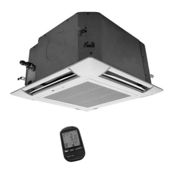
INTRODUCTION INTRODUCTION General The CN DCI Inverter Cassette type split air conditioner range comprise RC (heat pump) models, as follows: CN 25 ● CN 35 ● CN 50 ● CN 60 ● CN 70 ● Main Features The CN DCI series benefits from the most advanced technological innovations, namely: DC inverter technology. -
Page 5: Appendix A
INTRODUCTION Indoor Unit The indoor unit is cassette type indoor unit, and can be easily fitted to many types of residential and commercials applications. It includes: Coil with hydrophilic aluminum fins. ● Motorized flaps (two step motors). ● Advanced electronic control box assembly (DCI storm). ●... -
Page 6: Indoor Units
INTRODUCTION Tubing Connections Flare type interconnecting tubing to be produced on site. For further details please refer to the Installation Manual, Chapter 10. Accessories Remote Control. Panel 625x625 for gird ceiling. Panel 725x725 for hard ceiling. ESF & Ionizer kit. Inbox Documentation Each unit is supplied with its own installation and operation manuals. -
Page 7: Cn 25 Dci Dci
PRODUCT DATA SHEET PRODUCT DATA SHEET CN 25 DCI R410A CN25 DCI Model Indoor Unit DCI 25 R410A Model Outdoor Unit Installation Method of Pipe Flared Characteristics Units Cooling Heating Btu/hr 8550(5100-12300) 10900(5100-16400) Capacity 2.5(1.5-3.6) 3.2(1.5-4.8) 0.59(0.45-1.00) 0.8(0.50-1.40) Power input 4.24... -
Page 8: Cn 35 Dci Dci
PRODUCT DATA SHEET CN 35 DCI R410A CN35 DCI Model Indoor Unit DCI 35 R410A Model Outdoor Unit Installation Method of Pipe Flared Characteristics Units Cooling Heating Btu/hr 11950(5800-14700) 14350(5450-18800) Capacity 3.5(1.7-4.3) 4.2(1.6-5.5) 0.96(0.50-1.30) 1.16(0.59-1.70) Power input 3.63 3.64 EER (Cooling) or COP(Heating) Energy efficiency class Power supply V/Ph/Hz... - Page 9 PRODUCT DATA SHEET CN 50 DCI R410A CN-50 DCI Model Indoor Unit DCI 50 R410A Model Outdoor Unit Installation Method of Pipe Flared Characteristics Units Cooling Heating Btu/hr 17050(4450-20500) 19100(4450-23900) Capacity 5.0(1.3-6.0) 5.6(1.3-7.0) 1.56(0.46-2.11) 1.55(0.36-2.50) Power input 3.22 3.62 EER (Cooling) or COP(Heating) Energy efficiency class Power supply V/Ph/Hz...
-
Page 10: Cn 60 Dci Dci
PRODUCT DATA SHEET CN 60 DCI R410A CN 60 DCI Model Indoor Unit DCI 60 R410A Model Outdoor Unit Installation Method of Pipe Flared Characteristics Units Cooling Heating Btu/hr 19800(4800~22200) 23200(6800~27300) Capacity 5.8(1.4-6.5) 6.8(2.0~8.0) 1.92(0.44-2.20) 2.11(0.52~2.60) Power input 3.02 3.22 EER (Cooling) or COP(Heating) Energy efficiency class Power supply... -
Page 11: Cn 70 Dci Dci 72Z
PRODUCT DATA SHEET CN 72(Z) DCI R410A CN70 DCI Model Indoor Unit DCI 72Z R410A Model Outdoor Unit Installation Method of Pipe Flared Characteristics Units Cooling Heating Btu/hr 23200(5110~25570) 24890(5110~28640) Capacity 6.8(1.5-8.0) 7.3(1.5~9.0) 2.41(0.5-2.65) 2.27(0.5~2.92) Power input EER (Cooling) or COP(Heating) 2.82 3.22 Energy efficiency class... - Page 12 PRODUCT DATA SHEET Optional accessory Panel 625x625(Optional accessory) For all the models Dimensions (H x L x D) 625x625x40 Weight PaCNage Dimensions (H x L x D) 700x700x103 PaCNage Weight Units per pallet units StaCNing height units 10 levels Panel 725x725(Optional accessory) For all the models Dimensions (H x L x D) 725x725x40...
-
Page 13: Rating Conditions
RATING CONDITIONS RATING CONDITIONS Standard conditions in accordance with ISO 5151, ISO 13253 (for ducted units) and EN 14511. Cooling: Indoor: C DB 19 C WB Outdoor: 35 C DB Heating: Indoor: C DB Outdoor: 7 C DB 6 C WB Operating Limits R410A DCI (Excluding Delta Units) Indoor... -
Page 14: Outline Dimensions
OUTLINE DIMENSIONS OUTLINE DIMENSIONS Indoor Unit: CN 25, 35, 50, 60, 70 R410A DCI Unit Main unit Insulation Front Front Front Effective Unit Body Model Step (C) width (D) height (E) Width (W) Height (H) 25/35 625/725 50/60/70 625/725 SM CN 1-E.1 GB CONTENT... - Page 15 OUTLINE DIMENSIONS Outdoor Unit: DCI 50 Outdoor Unit: DCI 60 SM CN 1-E.1 GB CONTENT...
- Page 16 OUTLINE DIMENSIONS Outdoor Unit: DCI 72Z SM CN 1-E.1 GB CONTENT...
-
Page 17: Performance Data & Pressure Curves
PERFORMANCE DATA & PRESSURE CURVES PERFORMANCE DATA CN 25 DCI 5.1.1 Cooling Capacity (kW) – Run Mode [230V] : Indoor Fan at High Speed. ID COIL ENTERING AIR DB/WB TEMPERATURE [C OD COIL 22/15 24/17 27/19 29/21 32/23 ENTERING AIR DB... - Page 18 PERFORMANCE DATA & PRESSURE CURVES 5.1.3 Heating Capacity (kW) - Run Mode [230V] : Indoor Fan at High Speed. ID COIL ENTERING AIR DB TEMPERATURE [C OD COIL ENTERING AIR DB/WB DATA TEMPERATURE [ 2.04 1.89 1.75 -15/-16 0.48 0.53 0.58 2.27 2.12...
- Page 19 PERFORMANCE DATA & PRESSURE CURVES 5.1.5 Model: CN 25 DCI Cooling - Test Mode Suction Pressure Vs.Outdoor Temp. 1400 Indoor 1300 DB/WB 1200 22/15 1100 24/17 1000 27/19 29/21 32/23 Outdoor DB Temperature[ºC ] Discharge Pressure Vs. Outdoor Temp. 4000...
- Page 20 PERFORMANCE DATA & PRESSURE CURVES 5.1.6 Heating - Test Mode Suction Pressure Vs.Outdoor Temp. 1300 1200 1100 1000 Outdoor WB Temperature [ºC] Discharge Pressure Vs. Outdoor Temp. 4000 3750 Indoor DB 3500 3250 3000 2750 2500 2250 2000 1750 1500 1250 1000 Outdoor WB Temperature [ºC]...
- Page 21 PERFORMANCE DATA & PRESSURE CURVES CN 35 DCI 5.2.1 Cooling Capacity (kW) - Run Mode [230V] : Indoor Fan at High Speed. ID COIL ENTERING AIR DB/WB TEMPERATURE [C OD COIL ENTERING AIR DB DATA 22/15 24/17 27/19 29/21 32/23 TEMPERATURE [ 80 - 110 % of nominal -10 - 20...
- Page 22 PERFORMANCE DATA & PRESSURE CURVES 5.2.3 Heating Capacity (kW) - Run Mode [230V] : Indoor Fan at High Speed. ID COIL ENTERING AIR DB TEMPERATURE [C OD COIL ENTERING AIR DB/WB DATA TEMPERATURE [ 2.67 2.49 2.30 -15/-16 0.70 0.77 0.84 2.98 2.79...
- Page 23 PERFORMANCE DATA & PRESSURE CURVES 5.2.5 Model: CN 35 DCI Cooling - Test Mode Suction Pressure VS.Outdoor Temp. 1400 Indoor DB/WB 1300 22/15 1200 24/17 1100 27/19 1000 29/21 32/23 Outdoor DB Temperature[ºC ] Discharge Pressure VS. Outdoor Temp. 4000 3750 Indoor 3500...
- Page 24 PERFORMANCE DATA & PRESSURE CURVES 5.2.6 Heating - Test Mode Suction Pressure VS.Outdoor Temp. 1300 1200 1100 1000 Outdoor WB Temperature [ºC] Discharge Pressure VS. Outdoor Temp. 4000 3750 3500 3250 Indoor DB 3000 2750 2500 2250 2000 1750 1500 1250 1000 Outdoor WB Temperature [ºC]...
- Page 25 PERFORMANCE DATA & PRESSURE CURVES CN 50 DCI 5.3.1 Cooling Capacity (kW) - Run Mode [230V] : Indoor Fan at High Speed. ID COIL ENTERING AIR DB/WB TEMPERATURE [C OD COIL ENTERING AIR DB DATA 22/15 24/17 27/19 29/21 32/23 TEMPERATURE [ 80 - 110 % of nominal -10 - 20...
- Page 26 PERFORMANCE DATA & PRESSURE CURVES 5.3.3 Heating Capacity (kW) - Run Mode [230V] : Indoor Fan at High Speed. ID COIL ENTERING AIR DB TEMPERATURE [C OD COIL ENTERING AIR DB/WB DATA TEMPERATURE [ 3.69 3.43 3.18 -15/-16 0.96 1.06 1.16 4.11 3.85...
- Page 27 PERFORMANCE DATA & PRESSURE CURVES 5.3.5 Model: CN 50 DCI Cooling - Test Mode Suction Pressure VS.Outdoor Temp. 1400 Indoor 1300 DB/WB 1200 1100 22/15 24/17 1000 27/19 29/21 32/23 Outdoor DB Temperature[ºC ] Discharge Pressure VS. Outdoor Temp. 4250 4000 Indoor 3750...
- Page 28 PERFORMANCE DATA & PRESSURE CURVES 5.3.6 Heating - Test Mode Suction Pressure VS.Outdoor Temp. 1100 1000 Outdoor WB Temperature [ºC] Discharge Pressure VS. Outdoor Temp. 4000 3750 Indoor DB 3500 3250 3000 2750 2500 2250 2000 1750 1500 1250 1000 Outdoor WB Temperature [ºC] 5-12 SM CN 1-E.1 GB...
- Page 29 PERFORMANCE DATA & PRESSURE CURVES CN 60 DCI 5.4.1 Cooling Capacity (kW) - Run Mode [230V] : Indoor Fan at High Speed. ID COIL ENTERING AIR DB/WB TEMPERATURE [C OD COIL 22/15 24/17 27/19 29/21 32/23 ENTERING AIR DB DATA TEMPERATURE [ 80 - 110 % of nominal -10 - 20...
- Page 30 PERFORMANCE DATA & PRESSURE CURVES 5.4.3 Heating Capacity (kW) - Run Mode [230V] : Indoor Fan at High Speed. ID COIL ENTERING AIR DB TEMPERATURE [C OD COIL ENTERING AIR DB/WB DATA TEMPERATURE [ 4.33 4.03 3.72 -15/-16 1.27 1.40 1.52 4.82 4.52...
- Page 31 PERFORMANCE DATA & PRESSURE CURVES 5.4.5 Model: CN 60 DCI Cooling – Test Mode Suction Pressure Vs.Outdoor Temp. 1100 Indoor 1050 DB/WB 1000 22/15 24/17 27/19 29/21 32/23 Outdoor DB Temperature[ Discharge Pressure Vs.Outdoor Temp. 4000 Indoor 3750 DB/WB 3500 3250 22/15 3000...
- Page 32 PERFORMANCE DATA & PRESSURE CURVES 5.4.6 Heating – Test Mode Suction Pressure Vs.Outdoor Temp. 1200 1100 1000 Indoor DB Outdoor WB Temperature[ Discharge Pressure Vs. Outdoor Temp. 3750 3500 3250 Indoor DB 3000 2750 2500 2250 2000 1750 1500 Outdoor WB Temperature[ 5-16 SM CN 1-E.1 GB CONTENT...
- Page 33 PERFORMANCE DATA & PRESSURE CURVES CN 70 DCI 5.5.1 Cooling Capacity (kW) - Run Mode [230V] : Indoor Fan at High Speed. ID COIL ENTERING AIR DB/WB TEMPERATURE [C OD COIL ENTERING AIR DB DATA 22/15 24/17 27/19 29/21 32/23 TEMPERATURE [ 80 - 110 % of nominal -10 - 20...
- Page 34 PERFORMANCE DATA & PRESSURE CURVES 5.5.3 Heating Capacity (kW) - Run Mode [230V] : Indoor Fan at High Speed ID COIL ENTERING AIR DB TEMPERATURE [C OD COIL ENTERING AIR DB/WB DATA TEMPERATURE [ 4.65 4.32 4.00 -15/-16 1.36 1.50 1.64 5.17 4.85...
- Page 35 PERFORMANCE DATA & PRESSURE CURVES 5.5.5 Model: CN 70 DCI Cooling – Test Mode Suction Pressure Vs. Outdoor Temp. 1000 Indoor DB/WB 22/15 24/17 27/19 29/21 32/23 Outdoor DB Temperature[ Discharge Pressure Vs. Temp. 3900 3700 Indoor 3500 DB/WB 3300 3100 22/15 2900...
- Page 36 PERFORMANCE DATA & PRESSURE CURVES 5.5.6 Heating – Test Mode Suction Pressure Vs. Outdoor Temp. 1050 Indoor DB Outdoor WB Temperature[ Discharge Pressure Vs. Outdoor Temp. 3700 3500 3300 Indoor DB 3100 2900 2700 2500 2300 2100 1900 1700 Outdoor WB Temperature[ 5-20 SM CN 1-E.1 GB CONTENT...
- Page 37 PERFORMANCE DATA & PRESSURE CURVES Capacity Correction Factor Due to Tubing Length 5.6.1 Cooling TOTAL TUBING LENGTH Model 7.5m 1.02 0.98 0.96 0.95 0.95 0.93 ז Minimum recommended tubing length between indoor and outdoor units is 3m.w 5.6.2 Heating TOTAL TUBING LENGTH Model 7.5m 1.02...
-
Page 38: Sound Level Characteristics
SOUND LEVEL CHARACTERISTICS SOUND LEVEL CHARACTERISTICS Sound Pressure Level 1.5m Unit Mic. Figure 1 Soud Pressure Level Spectrum (Measured as Figure 1) CN 25 CN 35 FAN SPEED LINE SM CN 1-E.1 GB CONTENT... - Page 39 SOUND LEVEL CHARACTERISTICS CN 50 CN 60 CN 70 FAN SPEED LINE SM CN 1-E.1 GB CONTENT...
- Page 40 SOUND LEVEL CHARACTERISTICS Outdoor units MODEL SPL dB(A) SPW dB(A) Indoor Outdoor Cooling/Heating Cooling/Heating CN 25 DCI 25 50/51 60/61 CN 35 DCI 35 52/52 62/62 CN 50 DCI 50 52/53 62/63 CN 60 DCI 60 55/55 65/65 CN 70 DCI 72Z 56/56 66/66...
- Page 41 SOUND LEVEL CHARACTERISTICS DCI 35 Cooling DCI 35 Heating DCI 50 Cooling DCI 50 Heating FAN SPEED LINE SM CN 1-E.1 GB CONTENT...
- Page 42 SOUND LEVEL CHARACTERISTICS DCI 60 Cooling DCI 60 Heating DCI 72 Cooling DCI 72 Heating FAN SPEED LINE SM CN 1-E.1 GB CONTENT...
-
Page 43: Electrical Data
ELECTRICAL DATA ELECTRICAL DATA Single Phase Units MODEL CN 25 DCI CN 35 DCI CN 50 DCI CN 60 DCI CN 70 DCI To indoor To indoor To indoor To indoor To outdoor Power Supply 1PH-230V-50Hz 1PH-230V-50Hz 1PH-230V-50Hz 1PH-230V-50Hz 1PH-230V-50Hz... -
Page 44: Wiring Diagrams
WIRING DIAGRAMS WIRING DIAGRAMS CN 25, 35, 50, 60, 70 DCI SM CN 1-E.1 GB CONTENT... - Page 45 WIRING DIAGRAMS Outdoor Unit: DCI 72Z SM CN 1-E.1 GB CONTENT...
-
Page 46: Refrigeration Diagrams
REFRIGERATION DIAGRAMS REFRIGERATION DIAGRAMS CN 25, 35, 50, 60, 70 DCI Cooling Mode Heating Mode E E V SM CN 1-E.1 GB CONTENT... - Page 47 TUBING CONNECTIONS TUBING CONNECTIONS TUBE (Inch) ¼” ⅜” ½” ⅝” ¾” TORQUE (Nm) Flare Nuts 11-13 40-45 60-65 70-75 80-85 Valve Cap 13-20 13-20 18-25 18-25 40-50 Service Port Cap 11-13 11-13 11-13 11-13 11-13 Valve Protection Cap-end Refrigerant Valve Port (use Allen wrench to open/close) Valve Protection Cap Refrigerant Valve Service Port Cap...
-
Page 48: Control System
CONTROL SYSTEM CONTROL SYSTEM 11.1 General Functions and Operating RulesThe DCI software is fully parametric. All the model dependent parameters are shown in Blue color and with Italic style [parameter]. The parameters values are given in the last section of this control logic chapter of the service man- ual. - Page 49 CONTROL SYSTEM SW 35V14 and above NLOAD Target Frequency [Hz] 0 < NLOAD ≤ MinFreq MinFreq MaxFreq MinFreq ˜ > MinFreq {min (NLOAD, LoadDeadZo MinFreq} MinFreq LoadDeadZo MinFreq Differences between Old and New ODU DCI/DCR software Unit Current software New software 35V12 35V14 Comment:...
- Page 50 CONTROL SYSTEM Target frequency limits as a function of outdoor air temperature (OAT): OAT Range Cooling Mode limits Heating Mode limits OAT < 6 No limit 6 ≤ OAT < 15 MaxFreqAsOATC MaxFreqAsOAT1H 15≤ OAT<28 MaxFreqAsOAT2H 28≤ OAT No limit 11.1.4 Frequency Changes Control When the unit is running normally , the compressor frequency change rate is 1 Hz/sec.
- Page 51 CONTROL SYSTEM 11.1.6 Minimum On and Off Time 3 minutes 11.1.7 Indoor Fan Control 8 Indoor fan speeds are determined for each model. 4 speeds for cool/dry/fan modes and 4speeds for heat mode. When user sets the indoor fan speed to a fixed speed (Low/ Medium/ High), unit will operate constantly at set speed.
- Page 52 CONTROL SYSTEM OFAN State 3 Degrees Change To Higher at Cool Mode OFAN Cool state (*1) 3 Degrees Change To lower Note: Periorities A>B>C OFAN Cool state If State C, change to B (*1) If State B, change to A When compressor is switched to OFF and the heat sink temperature is above 55 degrees, the outdoor fan will remain ON in low speed for up to 3 minutes.
- Page 53 CONTROL SYSTEM 11.1.9 EEV (Electronic Expansion Valve) Control 11.1.9.1 EEV Control for DCI25/35/50/60 EEV opening is defined as EEV = EEV + EEV is the initial EEV opening as a function of the compressor frequency, operation mode, unit model and capacity. is a correction value for the EEV opening that is based on the compressor temperature.
- Page 54 CONTROL SYSTEM 11.1.10 RV(Reversing Valve) Control Reversing valve is on in heat mode. Switching of RV state is done only after compressor is off for over 3 minutes. 11.1.10.1 Ioniser Control Ioniser is on when unit is on ,AND indoor fan is on ,AND Ioniser power switch (on grille) is on. 11.1.10.2 Base Heater Control The base heater will be working only when RV is “ON”...
- Page 55 CONTROL SYSTEM 11.1.11.2 Indoor Fan Control in Heating Mode Indoor fan speed depends on the indoor coil temperature: 11.1.14 Auto Cool/Heat Mode When in auto cool heat mode unit will automatically select between cool and heat mode according to the difference between actual room temperature and user set point temperature (.T). Unit will switch from cool to heat when compressor is off for 3 minutes, and .T <...
- Page 56 CONTROL SYSTEM 11.1.16.2 Indoor Coil Defrost Protection — CN Trend Fast Increasing Increasing No Change Decreasing Fast Decreasing < -2 [-2, 0) [0, 2) [2, 4) [4, 6) Norm Norm [6, 8] Norm Norm Norm > 8 Norm 11.1.16.3 Indoor Coil Overheating Protection ICT Trend Fast Decreasing Decreasing...
- Page 57 CONTROL SYSTEM 11.1.17.2 Compressor Over Current Protection Only For DCI25/35/50/60/72Z Stop-Compresor CCROC4 HzDown2 CCROC3 HzDown1 CCROC2 Stop-Rise CCROC1 Normal 11.1.18 Heat Sink Overheating Protection 11.1.08.1 Heat Sink Overheating Protection For DCI25/35/50/60/72Z HST Trend Fast Decreasing Decreasing No Change Increasing Fast Increasing ≥...
- Page 58 CONTROL SYSTEM • Deicing Operation Procedure O C T T h re s h o ld C O M P D e ic e F re q C h R V m a x. 1 2 m in u te s H E A T C O O L O F A N...
- Page 59 CONTROL SYSTEM Overflow when Overflow when unit is ON unit is OFF Overflow Water Level Normal OPER BLINK NLOAD is NLOAD forced to 0 PUMP 8 min 8 min 8 min Operating the Unit from Mode Button (On display) 11.1.21 Forced operation allows to start, stop and operate in Cooling or Heating, in pre-set temperature according to the following table: Forced operation Mode...
- Page 60 CONTROL SYSTEM 11.1.22.2 Outdoor Unit controller Indicatiors Unit has three LED’s. SB LED is ON when power is ON (230 VAC, even when no communication). STATUS LED is ON when COMP is ON, and Blinks according to diagnostics mode definitions when either fault or protection occurs.
- Page 61 CONTROL SYSTEM 11.1.23.3 Main PCB − CN MCU Flash Port IF Motor ICTE sensor ICT sensor RAT sensor M2L Port DIP Switch WATER level Unit On output ALARM output RCW Power 16 Pins Display (not used) To Display Water Pump Fresh Air 11-14 SM CN 1-E.1 GB...
- Page 62 CONTROL SYSTEM 11.1.24 Self Test Jumper(J1)) ● Jumper for production line only, never install jumper on site! 11.1.25 DIP Switch and Jumper Settings ● CN - Dip switch default setting for each model MODEL 2.5 KW 3.5 KW 5.0 KW 6.0 KW 7.0 KW ●...
- Page 63 CONTROL SYSTEM ● Presence Detector/Power Shedding Selection Select the functions of dry contact PD/PS by setting the Dip switch J9 Selection Presence Detector Power Shedding ● Installation of height compensation settings (By installer) The compensation settings according to installation height should be set by using the dip switch J12, J13 on the controller PCB Installation Height Installation height...
- Page 64 CONTROL SYSTEM IDU Diagnostic Table. ● Alarm Output The Alarm Output dry contact will be on (closed), when a predefined set faults occur. The fault set is defined under diagnostics section. The alarm output will be off (open), when the predefined fault is cleared. The indoor alarm outputs are defined according to the following IDU Diagnostic Table: Problem ICT is disconnected...
- Page 65 CONTROL SYSTEM OUD Diagnostic Table AO - Alarm output Problem OCT is disconnected OCT is shorted CTT is disconnected CTT is shorted HST is disconnected (when enabled) HST is shorted (when enabled) OAT is disconnected (when enabled) OAT is shorted (when enabled) TSUC is disconnected (when enabled) TSUC is shorted (when enabled) IPM Fault...
-
Page 66: Test Mode
CONTROL SYSTEM 11.1.25 Outdoor Unit Controller 11.1.25.1 Outdoor Unit Controller - Jumper setting JP9 Jumper Layout Reserved (PIN 9) ODU3 (PIN 7) ODU2 (PIN 5) ODU1 (PIN 3) ODU0 (PIN 1) GND (PIN 10) GND (PIN 8) (PIN 6) (PIN 4) (PIN 2) 11.1.26 ODU Model Selection... - Page 67 CONTROL SYSTEM 11.2.3 Unit Operation in Test Mode In test mode, the unit will operate in fixed settings according to the indoor fan speed setting: Indoor FAN Speed Setting Unit Setting Minimum Capacity Setting Turbo Nominal Capacity Setting Auto Maximum Capacity Setting During test mode, protections are disabled, except for stop compressor status.
- Page 68 CONTROL SYSTEM 11.3.2 Family Dependent Parameter Name BasicCV1 BasicCV2 BasicCV3 BasicCV4 Max_Swg Min_H_Angle Max_H_Angle Min_C_Angle Max_C_Angle MTR_Cls_Dir MTR_Cls_Dir_V Max_Angle_V Min_Angle_V Max_Swg_V IFSPCHNA IFSPCHND IFSPCHAA IFSPCHAD IFSTARTSPEED ICTSTSpeed ICTVLSpeed ICTLSpeed ICTHSpeed ICTTSpeed NLOADHForcedValue ICTOH1 ICTOH2 ICTOH3 ICTOH4 ICTOH5 ICTOH6 ICTEEnable SM CN 1-E.1 GB 11-21 CONTENT...
- Page 69 CONTROL SYSTEM 11.3.3 Indoor Model Parameters: Indoor Family Indoor Model Parameter IFVLOWC IFLOWC IFMEDC 1050 1050 IFHIGHC 1100 1170 1200 IFTURBOC 1000 1060 1170 1240 1280 IFVLOWH IFLOWH IFMEDH 1050 1050 IFHIGHH 1100 1170 1200 IFTURBOH 1000 1060 1220 1240 1280 Cap .Group NomLoadC...
- Page 70 CONTROL SYSTEM 11.3.4 Outdoor Parameters General Parameters ( for every software): Name Default Value MinOFFTime MinONTime OFSPCH Down1 Down2 DImin DImax TimeD DTmin DTmax CTMRUP HSTOH1 HSTOH2 HSTOH3 HSTOH4 HSTOH5 HSTOHDelta1 HSTOHDelta2 EEVCVTConst BalanceTime EEVInitOpen SM CN 1-E.1 GB 11-23 CONTENT...
- Page 71 CONTROL SYSTEM 11.3.5 ODU Model Dependent Parameters ( 35V12 ) Outdoor Model Single Single Single Single Parameter DCI-25 DCI-35 DCI-50 DCI 60 MinFreqC MaxFreqC MinFreqH MaxFreqH NormAccel NormDecel Step1Freq Step2Freq Step3Freq OFVL OFLOWC OFMEDC OFMAXC OFLOWH OFMEDH OFMAXH OFANTESTMODEC OFANTESTMODEH OFDelTestMode CTTOH1 CTTOH2...
- Page 72 CONTROL SYSTEM 11.3.6 ODU Model Dependent Parameters ( 35V14 ) Outdoor Model Single Single Single Single Parameter DCI-25 DCI-35 DCI-50 DCI 60 MinFreqC MaxFreqC MaxFreqCRunPhase MinFreqH MaxFreqH MaxFreqHRunPhase LoadDeadZoneC LoadDeadZoneH NormAccel NormDecel Step1Freq Step2Freq Step3Freq OFVL OFLOWC OFMEDC OFMAXC OFLOWH OFMEDH OFMAXH OFANTESTMODEC...
- Page 73 CONTROL SYSTEM 11.3.7 ODU Model Dependent Parameters ( 36V1-S01 ) Outdoor Model Single Parameter DCI-72Z MinFreqC MaxFreqC MinFreqH MaxFreqH Step1Freq Step2Freq Step3Freq OFMinRPM OFMaxRPM NightRPM OFNNoiseMaxRPM CTTOH1 CTTOH2 CTTOH3 CTTOH4 CCROC1 12.5 CCROC2 11.3 CCROC3 14.1 CCROC4 14.9 ProtFreqLimit EEVMinOperOpenC EEVMaxOperOpenC EEVMinOperOpenH EEVMaxOperOpenH...
-
Page 74: Troubleshooting
TROUBLESHOOTING TROUBLESHOOTING WARNING!!! When Power Up – the whole outdoor unit controller, including the wiring, is under HIGH VOLTAGE!!! Never open the Outdoor unit before turning off the Power!!! When turned off, the system is still charged (400V)!!! It takes about 3 Min. to discharge the system. Touching the controller before discharging may cause an electrical shoCN!!! For safe handling of the controller please refer to section 12.6 below. - Page 75 TROUBLESHOOTING PROBABLE SYMPTOM CORRECTIVE ACTION CAUSE Problem with outdoor CheCN outdoor fan motor according Compressor is on but outdoor electronics or to the procedure in section 12.5.3 , if fan does not work outdoor fan not OK replace controller CheCN RV power connections, if Unit works in wrong mode Electronics or power (cool instead of heat or heat...
- Page 76 TROUBLESHOOTING When system enters diagnostics mode, only one fault code is shown. Order of priority is from the lower to the higher number. Diagnostics is continuously ON as long as power is ON. The current system operation mode will not be changed. If no fault occurred in the system, no fault code will be displayed during normal operation mode.
- Page 77 TROUBLESHOOTING Problem Model A Model B Model C Model D CN / LSN Units only 12.3.2 Indoor Unit Diagnostics and Corrective Actions Fault Probable Cause Corrective Action Sensor failures CheCN sensor connections or of all types replace sensor Indoor and Outdoor Communication controllers are with Replace Indoor controller...
- Page 78 TROUBLESHOOTING Problem OMT is shorted (DCI72 / 72Z / 80) IPM Fault Bad EEPROM DC under voltage DC over voltage AC under voltage Mismatch IDU & ODU models (*SW 35V14 and above) No Communication Reserved Heat sink Over Heating Deicing Compressor Over Heating Compressor Over Current No OFAN FeedbaCN...
- Page 79 TROUBLESHOOTING Fault Probable Cause Corrective Action Switch unit to STBY and restart still cheCN compressor (12.5.4) Compressor LoCN If comp is ok replace OU controller If compressor is not ok replace compressor Communication quality CheCN Indoor to Outdoor Bad Communication is low reliability wiring and grounding 12.4...
- Page 80 TROUBLESHOOTING 12.5.4 CheCNing the Compressor. The compressor is brushless permanence magnetic DC motor. Three coil resistance is same. CheCN the resistance between three poles. The normal value should be below 0.5 ohm (TBD). 12.5.5 CheCNing the Reverse Valve (RV). Running in heating mode, cheCN the voltage between two pins of reverse valve connector, normal voltage is 220VAC.
-
Page 81: Exploded Views And Spare Parts Lists
EXPLODED VIEWS AND SPARE PARTS LISTS EXPLODED VIEWS AND SPARE PARTS LISTS 13.1 Indoor Unit: CN 25, 35. 50, 60, 70 DCI SM CN 1-E.1 GB 13-1 CONTENT... - Page 82 EXPLODED VIEWS AND SPARE PARTS LISTS 13.2 Indoor Unit: CN 25, 35 DCI Part No. Description Unit 453189500 Grille 453189900 Filter Assy. 453192700 Water-Level Switch 465720163 Front Plate Assy (625x625) 465720169 Front Plate Assy (725x725) ION/CN Airwell 465080003 Display Cover 462350078 Evaporator Assy/CN DCI 25/35 R410A 453192600...
- Page 83 EXPLODED VIEWS AND SPARE PARTS LISTS Part No. Description Unit 453193500 Ionizer(option) 465800090 Support 2/lever Assy/CN 465360028 Orienting Support/Lever 464000020 Base Plate Assy./CN DCI 463750123 Liquid Pipe Assy. /6.35 463750122 Gas Pipe Assy./9.53 464250047 Fixing Plate/Evaporator (Low height) 470100003 Cushion Rubber 465120005 Air Intake Panel (Low) 453195100...
- Page 84 EXPLODED VIEWS AND SPARE PARTS LISTS 13.3 Indoor Unit: CN 50, 60 DCI Part No. Description Unit 453189500 Grille 453189900 Filter Assy. 453192700 Water-Level Switch 465720163 Front Plate Assy. 625x625 465720169 Front Plate Assy. 725x725 ION/CN Airwell 465080003 Display Cover 462350077 Evaporator Assy./CN DCI 50/60 R410A 453192600...
- Page 85 EXPLODED VIEWS AND SPARE PARTS LISTS Part No. Description Unit 453193500 Ionizer(option) 465800090 Support 2/lever Assy/CN 465360028 Orienting Support/Lever 464000020 Base Plate Assy./CN DCI 463750124 Liquid Pipe Assy. /6.35 463750120 Gas Pipe Assy./12.7 453188400 Fixing Plate/Evaporator high) 470100003 Cushion Rubber 453190900 Air Intake Panel (high) 453195100...
- Page 86 EXPLODED VIEWS AND SPARE PARTS LISTS 13.4 Indoor Unit: CN 70 DCI Part No. Description Unit 453189500 Grille 453189900 Filter Assy. 453192700 Water-Level Switch 465720163 Front Plate Assy. 625x625 465720169 Front Plate Assy. 725x725 ION/CN Airwell 465080003 Display Cover 462350079 Evaporator Assy./CN DCI 70 R410A 453192600 Pump CN...
- Page 87 EXPLODED VIEWS AND SPARE PARTS LISTS Part No. Description Unit 465800090 Support 2/lever Assy/CN 465360028 Orienting Support/Lever 464000020 Base Plate Assy./CN DCI 453194200 Liquid Pipe Assy. /9.53 453194500 Gas Pipe Assy./15.88 453188400 Fixing Plate/Evaporator (high) 470100003 Cushion Rubber 453190900 Air Intake Panel (high) 453195100 Drain Jam 465800091...
- Page 88 EXPLODED VIEWS AND SPARE PARTS LISTS 13.5 Outdoor Unit: ONG3 25, 35 DCI 13-8 SM CN 1-E.1 GB CONTENT...
- Page 89 EXPLODED VIEWS AND SPARE PARTS LISTS 13.6 Outdoor Unit: ONG3 25, 35 DCI Part No. Description Unit 433218 Front panel A 4526340 Air inlet ring-420 433223 Painting insulation plate 4526476 Axial fan OD=401 4527092 DC motor for DCI25/35 433215 Motor support 4523060 Base painting Assy.
- Page 90 EXPLODED VIEWS AND SPARE PARTS LISTS 13.9 Outdoor Unit: ONG3 50 DCI 13-10 SM CN 1-E.1 GB CONTENT...
- Page 91 EXPLODED VIEWS AND SPARE PARTS LISTS 13.10 Outdoor Unit: ONG3 50 DCI Part No. Description Unit 433218 Front panel A 4526340 Air inlet ring-420 433223 Painting insulation plate 4526476 Axial fan OD=401 4526475 DC motor for DCI 50 4526457 Motor support 4527363 Base painting Assy.
- Page 92 EXPLODED VIEWS AND SPARE PARTS LISTS 13.11 Outdoor Unit: DCI 60 13-12 SM CN 1-E.1 GB CONTENT...
- Page 93 EXPLODED VIEWS AND SPARE PARTS LISTS 13.12 Outdoor Unit: DCI 60 Part No Description Unit 4517144 FAN COVER PP+UV 452795700 PAINTED LEFT CABINET ASSY 4521642 Painted Right Cabinet and Isolation Assy. 4523141 M10 Hexagon loCNed nut M10 4526841 cusion for fan 4526510 FAN D=460mm (3 blade) 453026500...
- Page 94 EXPLODED VIEWS AND SPARE PARTS LISTS 13.13 Outdoor Unit: DCI 72Z 13-14 SM CN 1-E.1 GB CONTENT...
- Page 95 EXPLODED VIEWS AND SPARE PARTS LISTS 13.14 Outdoor Unit: DCI 72Z Item Description Quan. 465100000 Grill/ DCI Trio 4523652 PAINTED LEFT CABINET ASSY 4523758 Nut M8 left 452960400 Outdoor Fan 461600023 4-Way Valve Assy. 4522509 4-way Valve Coil 4526522 FOUR-WAY VALVE R410A 466130002R DC Motor 70W 8P 4522601...
- Page 96 APPENDIX A APPENDIX A INSTALLATION AND OPERATION MANUAL ► OPERATION MANUAL RC4 ► OPERATION MANUAL CN DCI ► INSTALLATION MANUAL CN DCI SM CN 1-E.1 GB 14-1 CONTENT...
Need help?
Do you have a question about the CN 25 DCI and is the answer not in the manual?
Questions and answers