Table of Contents
Advertisement
S
C
U
S
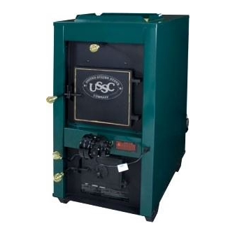
THE WOOD AND COAL FURNACE
SAFETY NOTICE: IF THIS FURNACE IS NOT PROPERLY INSTALLED, A HOUSE FIRE
MAY RESULT. FOR YOUR SAFETY, FOLLOW THE INSTALLATION DIRECTIONS.
CONTACT LOCAL BUILDING OR FIRE OFFICIALS ABOUT RESTRICTIONS AND
INSTALLATION REQUIREMENTS IN YOUR AREA.
Installation/Operator's Manual #851062H
UNITED S
UNITED S T T T T T A A A A A TES
UNITED S
UNITED S
UNITED S
S S S S S T T T T T O O O O O VE C
VE C
VE C OMP
VE C
VE C
Keeping America Warm Since 1869
MODEL: 1600G / 1800G
1
TES
TES
TES
TES
OMP
OMP ANY
OMP
ANY
ANY
ANY
OMP
ANY
Advertisement
Table of Contents

Related Manuals for USSC 1600G


Summary of Contents for USSC 1600G
- Page 1 VE C OMP ANY VE C Keeping America Warm Since 1869 MODEL: 1600G / 1800G THE WOOD AND COAL FURNACE SAFETY NOTICE: IF THIS FURNACE IS NOT PROPERLY INSTALLED, A HOUSE FIRE MAY RESULT. FOR YOUR SAFETY, FOLLOW THE INSTALLATION DIRECTIONS.
-
Page 2: Chimney Requirements
CLEARANCES INTRODUCTION Thank you for your purchase of a U.S. Stove Woodburning FLAMMABLE WALL furnace. Your decision to buy our Clayton Furnace was undoubt- edly reached after much careful thought and consideration. We Model 1600 - 22" Model 1600 - 17" are very proud you chose the U.S. -
Page 3: Smoke Pipe Installation
NOTE: Type of chimney: Class A All-Fuel UL 103HT on the flue lining. When ignited, this creosote makes an extremely hot fire. The chimney connector and chimney should be inspected at TOP OF CHIMNEY MUST CAP SHOULD HELP least twice monthly during the heating season to determine if a BE 2 FT. -
Page 4: Dampers On Stove Pipes
maintains clearances, keeps condensation and creosote within HEATED AIR DISCHARGE the pipe, and is capable of withstanding a two to three thousand The Clayton furnace is designed for use as a supplemental degree chimney fire. heating source. When used as a supplementary furnace, the 1. -
Page 5: Incorrect Installation
INSTALLATION NO. 2 INSTALLATION NO. 3 Extending the hot air duct from the furnace into the existing The baffle on this system should be made the full width of the plenum will help direct the flow of air from the 1600/1800 as well furnace plenum in order to properly direct the air into the as the flow in the existing furnace. -
Page 6: Brick Installation
ASSEMBLY INSTRUCTIONS Your furnace is shipped from the factory in four (2) packages. 1) BRICK INSTALLATION the furnace, 2) the blower. The draft kit and parts box containing (PRE-INSTALLED AT FACTORY) all parts necessary, and the fan limit kit and control center are boxed and packed in the firebox or ash pan. - Page 7 SMOKE CHAMBER (If re-assembly is necessary): 1. Place #1 firebrick in the back of smoke chamber. 2. Slide baffle plate into smoke chamber, flat side down. 3. Place remaining firebrick in smoke chamber as numbered below. (In placing the firebrick in the smoke chamber, lift the left side of firebrick first and drop into place.) See Illustrations below.
- Page 8 DISTRIBUTION BLOWER INSTALLATION SMOKE DOOR INSTALLATION Distribution blower slides onto rear of furnace. Engage blower flange with channels and press down. SMOKE DOOR CLIPS 1/4" LOCK NUTS 1/4" X 1-1/4" CARRIAGE BOLTS FRONT FURNACE SHAKER GRATE HANDLE INSTALLATION 1. Attach angle with two 1/4" x 3/4" hex bolts and two 1/4" SMOKE DOOR lock nuts.
- Page 9 FORCED AIR DRAFT (SHIPPED WITH UNIT) 1. Using (2) 1/4" x 1" bolt, lock washer and nut, attach draft adapter bracket to furnace draft tube. MODEL 1600/1800 KIT #69189 MOUNTING PROCEDURE FOR DRAFTS OPTIONAL MOTORIZED NATURAL DRAFT Models 1600 / 1800 1.
-
Page 10: Electrical Installation
ELECTRICAL INSTALLATION ALL WIRING MUST BE DONE BY A Predrilled holes are provided on the back of the furnace for THERMOSTAT mounting the fan center electrical box. QUALIFIED ELECTRICIAN The flexible conduit connecting the high limit control to the fan center electrical box has been sized longer for the model 1800. -
Page 11: Wiring Diagram
WIRING DIAGRAM FAN "OFF" LIMIT INDICATOR INDICATOR Honeywell (100) (200) LOAD LOAD FAN "ON" LIMIT BREAK OFF LIMIT SWITCH LINE LINE INDICATOR JUMPER FOR LOW VOLTAGE (150) SETTING LIMIT CONTROL WALL THERMOSTAT BLOWER MOTOR WHITE COMMON 1400 CFM BLACK 1250 CFM BLUE DRAFT 1100 CFM... -
Page 12: Testing And Operating Procedures
TESTING AND OPERATING PROCEDURES TESTING: established, you are ready to load the furnace. 1. Check the draft blower by turning the room thermostat CAUTION: To prevent flame and smoke spillage, the slide baffle up high enough so that the draft blower turns on. Then must be pulled out and the fuel door must be cracked for ten lower the thermostat setting until you hear it shut off. -
Page 13: Operating Notes
Slow fires: It is not recommended burning the Clayton furnace 2. NEVER completely cover the live fire with fresh coal. Always leave a generous area of glowing coal at the top any more than necessary early in the fall and late spring, as you of the fire and at the rear. -
Page 14: Trouble Shooting And Problem Solving
TROUBLE SHOOTING AND PROBLEM SOLVING 1. Problem: D. Check chimney draft — make sure chimney flue pipe is clean and chimney is of adequate height. Smoke puffs from furnace E. Make sure you're not suffocating the fire with Solution: excessive amounts of unburned wood. A. -
Page 15: Parts List
PARTS LIST MODEL 1600/1800 !! IMPORTANT !! NOTE: 1600 = 16 - FULL BRICK When ordering repair parts, 3- HALF BRICK a "G" must be added to the 1800 = 22 - FULL BRICK end of the part number of 2- HALF BRICK any part painted GREEN on the furnace. - Page 16 PARTS LIST MODEL 1600/1800 ITEM DESCRIPTION PART# ITEM DESCRIPTION PART# Top Safety Latch 23786 1/4" x 3/4" Hex Bolt 83339(6) Feed Door (Drilled) 69091 1/-20 Kep Nuts 83250(8) Ash Door (Drilled) 68880 1/4" x 1" Hex Bolt 83379 Door Latch Handle 24179(2) 1/4"...
- Page 17 PARTS LIST MODELS 1600 / 1800 Fan Limit Kit #C68399 ITEM DESCRIPTION PART# High Limit Control 80145 3-Speed Switch 80361 Plastic Knob C9267M Fan Center 80130 MODEL 1600 / 1800 Blower Kit #C60471 (1400CFM)
-
Page 18: Item Description
MOTORIZED NATURAL DRAFT PARTS LIST PRE-ASSEMBLED AT FACTORY (OPTIONAL KIT) MODEL 1600 / 1800 ITEM DESCRIPTION PART# Draw Band 23888 1/4" x 1" Bolt 83379 1/4" Lock Washer 83414 1/4" Hex Nut 83072 Erie Motor-120v C45099 Draft Cap 23859 MODEL 1600/1800 Draft Tube Weldment 68872 MND KIT #C60357M... - Page 19 FORCED AIR DRAFT PARTS LIST PRE-ASSEMBLED AT FACTORY MODEL 1600/1800 KIT #69189 ITEM DESCRIPTION PART# Draft Blower 80422 Power Supply Cord C40899 FAD Bracket 69192 10-24 Kep Nut (3ea.) 83244 1/4-20 x 1" Bolt (2ea) 83379 1/4-20 Lock Nut 83261...
-
Page 20: Installation Of Optional Equipment
INSTALLATION OF OPTIONAL EQUIPMENT INSTALLING DOMESTIC HOT WATER COIL 1. Remove access panel at rear of enclosure. 2. With a utility knife cut out the section of fiberglass insulation directly behind the access panel. 3. Remove cover plate from rear of firebox. ACCESS PANEL 4. - Page 21 INSTALLING BACK DRAFT DAMPER A back draft damper may be installed in either a vertical or horizontal section of the hot air duct. It should be positioned as close to the plenum opening of the furnace as practical. Press female end of the back draft damper over Hotblast Furnace collar or male end of the duct pipe.
- Page 22 FILTER BOX OPTION MODEL 1600 / 1800 20" x 20" x 1" Filter Required Assemble filter box sections in the order shown in the illustration and secure with sheet metal screws provided. 1. Assemble parts B and C to part E - bottom. 2.
- Page 23 DELUXE FILTER BOX 4. Attach filter holders to sides of enclosure with sheet metal KIT #C61999 screws. Model 1600/1800 16" x 20" x 1" Filter Required 16" x 20" opening 1. Attach sides of filter box to bottom with (4) sheet metal screws side.
-
Page 24: How To Order Repair Parts
HOW TO ORDER REPAIR PARTS THIS MANUAL WILL HELP YOU OBTAIN EFFICIENT, DEPENDABLE SERVICE FROM THE HEATER, AND ENABLE YOU TO ORDER REPAIR PARTS CORRECTLY. KEEP IN A SAFE PLACE FOR FUTURE REFERENCE. WHEN WRITING, ALWAYS GIVE THE FULL MODEL NUMBER WHICH IS ON THE NAMEPLATE ATTACHED TO THE BACK OF THE HEATER.
Need help?
Do you have a question about the 1600G and is the answer not in the manual?
Questions and answers