Table of Contents
Advertisement
Available languages
Available languages
Quick Links
Federal regulations require ceiling fans
with light kits manufactured or imported
after January 1, 2009, to limit total
wattage consumed by the light kit to
190W.
Therefore, this fan is equipped
with a wattage limiting device.
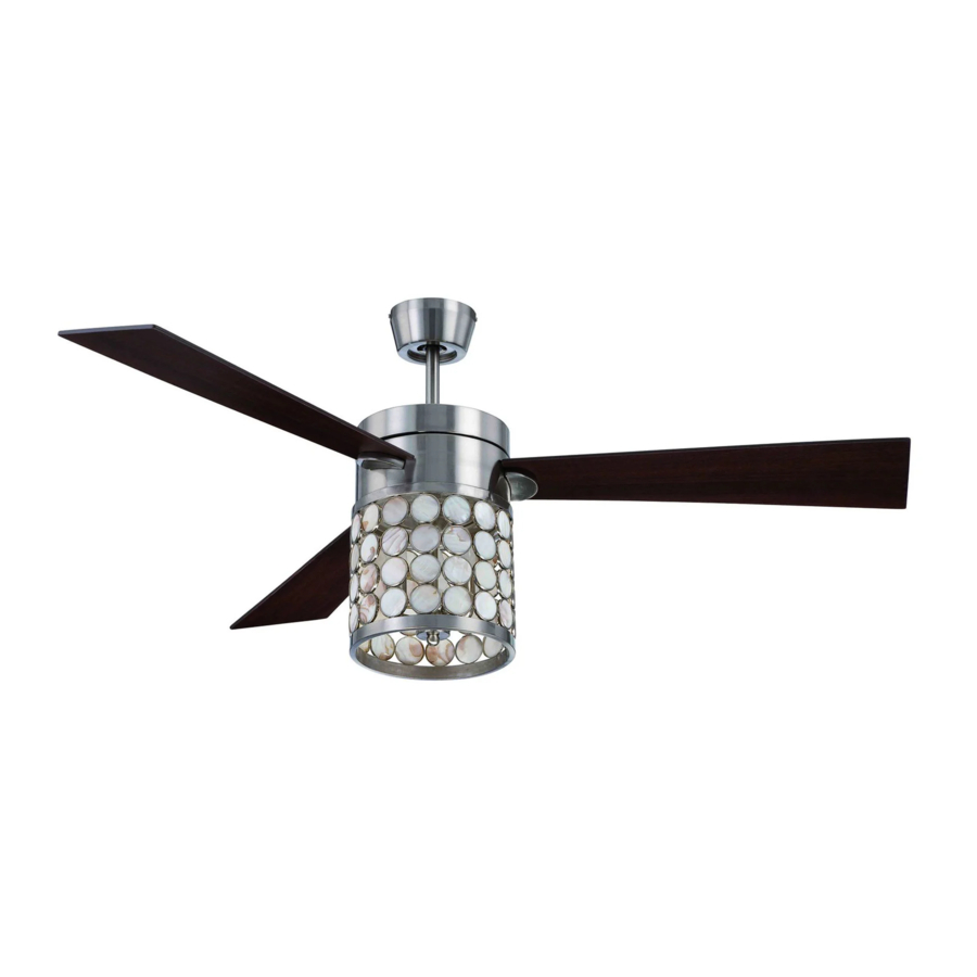
Installation Guide
For Model:
KAP54BNK3
E192641
net weight of fan: 17.53 lb (7.95 kg)
READ THESE INSTRUCTIONS AND
SAVE THEM FOR FUTURE USE
Table of Contents:
Safety Tips. pg. 1
Unpacking Your Fan. pg. 2
Parts Inventory. pg. 2
Installation Preparation. pg. 3
Hanging Bracket Installation. pg. 3
Fan Assembly. pgs. 4 - 5
Wiring. pg. 6
Canopy Assembly. pg. 7
Blade Assembly. pg. 7
Light Kit Assembly. pg. 8
Wall Control Operation. pg. 9
Remote Control Operation. pg. 10
Testing Your Fan. pg. 10
Troubleshooting. pg. 11
Warranty. pg. 11
Parts Replacement. pg. 11
PRINTED IN CHINA
Advertisement
Chapters
Table of Contents

Related Manuals for Craftmade KAP54BNK3


Summary of Contents for Craftmade KAP54BNK3
-
Page 1: Table Of Contents
190W. Therefore, this fan is equipped with a wattage limiting device. Installation Guide For Model: KAP54BNK3 Table of Contents: Safety Tips. pg. 1 Unpacking Your Fan. pg. 2 Parts Inventory. pg. 2 Installation Preparation. pg. 3 Hanging Bracket Installation. -
Page 2: Safety Tips
SAFETY TIPS. WARNING: To reduce the risk of electrical shock, turn off the electricity to the fan at the main fuse box or circuit panel before you begin the fan installation or before servicing the fan or installing accessories. READ ALL INSTRUCTIONS AND SAFETY INFORMATION CAREFULLY BEFORE INSTALLING YOUR FAN AND SAVE THESE INSTRUCTIONS. -
Page 3: Unpacking Your Fan
1. Unpacking Your Fan. Carefully open the packaging. Remove items from Styrofoam inserts. Remove motor housing and place on carpet or Styrofoam to avoid damage to finish. Do not discard fan carton or Styrofoam inserts should this fan need to be returned for repairs. -
Page 4: Installation Preparation
3. Installation Preparation. blade edge To prevent personal injury and damage, inches 7 feet (76cm) ensure that the hanging location allows the (2.13m) blades a clearance of 7 feet (2.13m) from the floor and 30in. (76cm) from any wall or 12ft - 20ft obstruction. -
Page 5: Fan Assembly. Pgs
5. Fan Assembly. If you wish to extend the hanging length of your fan, you must remove the hanging ball from the set screw set screw hole downrod provided to use with an extended stop pin downrod (sold separately). [If you wish to use the downrod provided, please proceed to instructions following the dotted line below.] hanging ball... - Page 6 5. Fan Assembly. (cont.) With the hanging bracket secured to the outlet box and able to support the fan, you safety cable loop wood are now ready to hang your fan. Grab the fan ceiling firmly with two hands. Slide downrod joist through opening in hanging bracket and let wood screw...
-
Page 7: Wiring
6. Wiring. Modifications not approved by the party responsible for compliance could void the user's authority to operate the equipment. *NOTE: This equipment has been tested and found to comply with the limits for a Class B digital device, pursuant to Part 15 of the FCC Rules. These limits are designed to provide CAUTION: Be sure outlet box is properly grounded reasonable protection against harmful interference in a residential installation. -
Page 8: Canopy Assembly
7. Canopy Assembly. receiver hanging bracket Temporarily raise canopy to hanging bracket to determine which 2 screws in hanging bracket align with slotted holes in canopy, and then lower antenna canopy and partially loosen these 2 screws. Remove the other 2 screws and set aside. Now, lift canopy to hanging bracket again, canopy aligning slotted holes in the canopy with... -
Page 9: Light Kit Assembly
9. Light Kit Assembly. motor housing Remove 1 screw from motor plate on underside of motor housing and partially loosen the other 2 screws. Align slotted holes in center of shade with loosened screws in motor motor plate plate, allowing molex connections from motor housing to come through hole in middle of shade. -
Page 10: Automated Learning Process./ Activating Code
10. Automated Learning Process./ TRANSMITTER Activating Code. (front) CAUTION: The remote control transmitter can be programmed to multiple receivers or fans. If this is not desired, turn wall switch off to any other programmable receiver or fan. This remote control transmitter is equipped with 16 code combinations to prevent possible interference from or to other remote units such as garage door openers, car alarms or security systems. -
Page 11: Remote Control Operation
12. Remote Control Operation. HI button - turns fan to HIGH speed MED button - turns fan to MEDIUM speed LOW button - turns fan to LOW speed OFF button - turns fan OFF button - controls LIGHT function: turns light ON/OFF when tapped quickly. -
Page 12: Troubleshooting
Return fan, shipping prepaid, to 4. Verify that receiver is wired properly. Craftmade/Ellington. We will repair or ship you a 5. Verify that wall control is wired properly. 6. Check to be sure fan is wired properly. - Page 13 Por lo tanto, este ventilador tiene un aparato que sirve para limitar el vatiaje. Guía de instalación Para modelo: KAP54BNK3 Indice de materias: Sugerencias de seguridad. Pág. 1 Desempaquetado del ventilador. Pág. 2 Inventario de piezas. Pág. 2 Preparación para la instalación. Pág. 3 Instalación del soporte de montaje.
-
Page 14: Sugerencias De Seguridad. Pág
SUGERENCIAS DE SEGURIDAD. ADVERTENCIA: Para evitar la posibilidad de una descarga eléctrica, desconectar la corriente en la caja de fusibles principal o el interruptor protector antes de iniciar la instalación del ventilador o antes de repararlo o instalar accesorios. LEER TODAS LAS INSTRUCCIONES E INFORMACION DE SEGURIDAD CUIDADOSAMENTE ANTES DE INSTALAR SU VENTILADOR Y GUARDAR ESTAS INSTRUCCIONES. -
Page 15: Desempaquetado Del Ventilador. Pág
1. Desempaquetado del ventilador. Abrir el empaque cuidadosamente. Sacar los artículos del embalaje. Sacar el motor y ponerlo en una alfombra o en el embalaje para evitar rayar el acabado. Guardar la caja de cartón o el empaquetamiento original en caso de que tenga que mandar el ventilador para alguna reparación. -
Page 16: Preparación Para La Instalación. Pág
3. Preparación para la instalación. borde del aspa 76cm Para prevenir daño corporal y otros daños, estar seguro de que el lugar en donde va a colgar el ventilador le 2,13 m pulg.) permite un espacio libre de 2,13m (7 pies) entre las (7 pies) puntas de las aspas y el piso y 76cm (30 pulg.) entre las aspas y cualquier pared u otra obstrucción. -
Page 17: Ensamblaje Del Ventilador. Págs
5. Ensamblaje del ventilador. Si usted desea extender la longitud colgante del agujero para ventilador, usted tendrá que quitar la bola que se tornillo el tornillo sirve para colgar del tubo provisto para usarla con de fijación un tubo más largo (a la venta por separado). [Si desea perno de fijación utilizar el tubo provisto, favor de pasar a las... - Page 18 5. Ensamblaje del ventilador. (cont.) Ya que esté sujetado el soporte de montaje bucle del cable a la caja de salida y capaz de apoyar el de seguridad viga de ventilador, usted está listo para colgar el madera ventilador. Agarrar el ventilador firmemente con las dos manos.
-
Page 19: Instalación Eléctrica. Pág
6. Instalación eléctrica. Las modificaciones no aprobadas por la parte responsable de la conformidad podrían invalidar la autorización del usuario para manejar el equipo. *NOTA: Se han hecho pruebas en este equipo y se ha comprobado que cumple con los límites para un PRECAUCION: Asegurarse de que la caja de salida esté... -
Page 20: Colocación De La Cubierta Decorativa. Pág
7. Colocación de la cubierta decorativa. receptor Temporalmente subir la cubierta decorativa al soporte soporte de de montaje para determinar cuáles 2 tornillos en el montaje soporte de montaje se alinean con los agujeros con ranura en la cubierta decorativa, y luego bajar la cubierta decorativa y parcialmente aflojar dichos tornillos. -
Page 21: Instalación Del Juego De Luz. Pág
9. Instalación del juego de luz. basidor del motor Quitar 1 tornillo de la placa del motor en el lado inferior del motor y aflojar los otros 2 tornillos. Alinear los agujeros con ranura en el centro de la pantalla con los tornillos aflojados en la placa del motor, dejando que las conexiones tipo "molex"... -
Page 22: Proceso De Aprendizaje Automático./ El Activar El Código. Pág
10. Proceso de aprendizaje automático./ El activar el código. TRANSMISOR PRECAUCION: Se puede programar el transmisor del control remoto para usar con varios receptores o ventiladores. Si no desea (lado principal) hacer esto, apagar el interruptor de cualquier otro receptor o ventilador programable. -
Page 23: Funcionamiento Del Control Remoto. Pág
12. Funcionamiento del control remoto. Botón HI - pone el ventilador en velocidad ALTA Botón MED - pone el ventilador en velocidad MEDIA Botón LOW - pone el ventilador en velocidad BAJA Botón OFF - APAGA el ventilador Botón - controla la función de LUZ: tocándolo ligeramente ENCIENDE/APAGA la luz. - Page 24 Problema: El juego de luz no se ilumina. Soluciones: Craftmade/Ellington pagará los gastos de envío de regreso. 1. Inspeccionar el interruptor de pared del ventilador. GARANTIA LIMITADA DE 6 AÑOS hasta DE POR VIDA: 2.
Need help?
Do you have a question about the KAP54BNK3 and is the answer not in the manual?
Questions and answers