Table of Contents
Advertisement
Available languages
Available languages
Quick Links
Federal regulations require ceiling fans
with light kits manufactured or imported
after January 1, 2009, to limit total
wattage consumed by the light kit to
190W.
Therefore, this fan is equipped
with a wattage limiting device.
Installation Guide
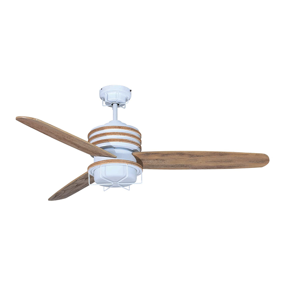
For Models:
MOR54ESP3
MOR54MWW3
APPROVED FOR USE
IN DAMP LOCATIONS
net weight of fan: 22.27 lb (10.1 kg)
READ THESE INSTRUCTIONS AND
SAVE THEM FOR FUTURE USE
Table of Contents:
Safety Tips. pg. 1
Unpacking Your Fan. pg. 2
Parts Inventory. pg. 2
Installation Preparation. pg. 3
Hanging Bracket Installation. pg. 3
Fan Assembly. pgs. 4 - 5
Wiring. pgs. 6 - 7
Canopy Assembly. pg. 7
Blade Assembly. pg. 8
Light Kit Assembly. pgs. 8 - 9
Wall Control Operation. pg. 10
Remote Control Operation. pg. 11
Testing Your Fan. pg. 11
Troubleshooting. pg. 12
Warranty. pg. 12
Parts Replacement. pg. 12
PRINTED IN CHINA
Advertisement
Chapters
Table of Contents

Related Manuals for Craftmade MOR54ESP3


Summary of Contents for Craftmade MOR54ESP3
-
Page 1: Table Of Contents
Therefore, this fan is equipped with a wattage limiting device. Installation Guide Table of Contents: For Models: Safety Tips. pg. 1 MOR54ESP3 Unpacking Your Fan. pg. 2 MOR54MWW3 Parts Inventory. pg. 2 Installation Preparation. pg. 3 Hanging Bracket Installation. pg. 3 Fan Assembly. -
Page 2: Safety Tips
SAFETY TIPS. WARNING: To reduce the risk of electrical shock, turn off the electricity to the fan at the main fuse box or circuit panel before you begin the fan installation or before servicing the fan or installing accessories. READ ALL INSTRUCTIONS AND SAFETY INFORMATION CAREFULLY BEFORE INSTALLING YOUR FAN AND SAVE THESE INSTRUCTIONS. -
Page 3: Unpacking Your Fan
1. Unpacking Your Fan. Carefully open the packaging. Remove items from Styrofoam inserts. Remove motor housing and place on carpet or Styrofoam to avoid damage to finish. Do not discard fan carton or Styrofoam inserts should this fan need to be returned for repairs. -
Page 4: Installation Preparation
3. Installation Preparation. blade edge To prevent personal injury and damage, ensure inches 7 feet (76cm) that the hanging location allows the blades a (2.13m) clearance of 7 feet (2.13m) from the floor and 30in. (76cm) from any wall or obstruction. 12 ft. -
Page 5: Fan Assembly. Pgs
5. Fan Assembly. set screw set screw hole stop pin If you wish to extend the hanging length of your fan, you must remove the hanging ball from the downrod provided to use with an extended downrod (sold hanging ball separately). - Page 6 5. Fan Assembly. (cont.) wood ceiling joist With the hanging bracket secured to the outlet box and able to support the fan, you are now ready to safety cable loop hang your fan. Grab the fan firmly with two hands. Slide downrod through opening in hanging bracket and let hanging ball rest on the hanging bracket.
-
Page 7: Wiring. Pgs
6. Wiring. ground (green or bare) white supply wire WARNING: Turn off circuit breakers to current fixture black supply wire from breaker panel and be sure switch is turned to the OFF position. ground (green or bare) blue CAUTION: Be sure outlet box is properly grounded and that a ground wire (GREEN or Bare) is present. -
Page 8: Canopy Assembly
6. Wiring. (cont.) Modifications not approved by the party responsible for compliance could void the user's authority to operate the equipment. IN ORDER TO WIRE WALL CONTROL, remove *NOTE: This equipment has been tested and found to comply with the limits for a Class B existing wall switch. -
Page 9: Blade Assembly
8. Blade Assembly. motor housing Locate 9 blade attachment screws and washers in hardware pack. Slide a blade through one of the narrow, rectangular openings on motor housing, aligning holes in blade with holes in blade arm (located on INSIDE of the underside of the motor housing)--refer to drawing at right. - Page 10 9. Light Kit Assembly. (cont.) motor housing Install two 60 watt max. candelabra base bulbs, (included). Locate slots on glass shade and align with nodules inside light kit fitter. Gently push up on glass light kit nodules fitter shade and turn to the RIGHT (clockwise) until it slides completely into place.
-
Page 11: Automated Learning Process./Activating Code
10. Automated Learning Process./Activating Code. CAUTION: The remote control transmitter can be programmed to multiple receivers or fans. If this is not desired, turn wall switch code transmitter off to any other programmable receiver or fan. switches (back) This remote control transmitter is equipped with 16 code combinations to prevent possible interference from or to other remote units such as garage door openers, car alarms or security systems. -
Page 12: Remote Control Operation
12. Remote Control Operation. HI button - turns fan to HIGH speed MED button - turns fan to MEDIUM speed LOW button - turns fan to LOW speed button - turns fan OFF button - turns light ON/OFF when pressed once; dims light when pressed and held down. -
Page 13: Troubleshooting
Return fan, shipping prepaid, to 4. Check to be sure fan is wired properly. Craftmade/Ellington. We will repair or ship you a 5. Verify wall control is wired properly. replacement fan, and we will pay the return shipping cost. - Page 14 Guía de instalación Indice de materias: Para modelos: Sugerencias de seguridad. Pág. 1 MOR54ESP3 Desempaquetado del ventilador. Pág. 2 MOR54MWW3 Inventario de piezas. Pág. 2 Preparación para la instalación. Pág. 3 Instalación del soporte de montaje. Pág. 3 Ensamblaje del ventilador.
-
Page 15: Sugerencias De Seguridad. Pág
SUGERENCIAS DE SEGURIDAD. ADVERTENCIA: Para evitar la posibilidad de una descarga eléctrica, desconectar la corriente en la caja de fusibles principal o el interruptor protector antes de iniciar la instalación del ventilador o antes de repararlo o instalar accesorios. LEER TODAS LAS INSTRUCCIONES E INFORMACION DE SEGURIDAD CUIDADOSAMENTE ANTES DE INSTALAR SU VENTILADOR Y GUARDAR ESTAS INSTRUCCIONES. -
Page 16: Desempaquetado Del Ventilador. Pág
1. Desempaquetado del ventilador. Abrir el empaque cuidadosamente. Sacar los artículos del embalaje. Sacar el motor y ponerlo en una alfombra o en el embalaje para evitar rayar el acabado. Guardar la caja de cartón o el empaquetamiento original en caso de que tenga que mandar el ventilador para alguna reparación. -
Page 17: Preparación Para La Instalación. Pág
3. Preparación para la instalación. borde del aspa Para prevenir daño corporal y otros daños, estar seguro 76cm de que el lugar en donde va a colgar el ventilador le 2,13m pulg.) permite un espacio libre de 2,13m (7 pies) entre las (7 pies) puntas de las aspas y el piso y 76cm (30 pulg.) entre las aspas y cualquier pared u otra obstrucción. -
Page 18: Ensamblaje Del Ventilador. Págs
5. Ensamblaje del ventilador. agujero para tornillo el tornillo de fijación perno de fijación Si usted desea extender la longitud colgante del ventilador, de tope usted tendrá que quitar la bola que sirve para colgar del tubo provisto para usarla con un tubo más largo (a la venta por separado). - Page 19 5. Ensamblaje del ventilador. (cont.) viga de madera bucle del cable Ya que esté sujetado el soporte de montaje a la caja de de seguridad salida y capaz de apoyar el ventilador, usted está listo para colgar el ventilador. Agarrar el ventilador firmemente con las dos manos.
-
Page 20: Instalación Eléctrica. Págs
6. Instalación eléctrica. ADVERTENCIA: Apagar los cortacircuitos en el panel toma de tierra (verde o pelada) de electricidad que suplan corriente a la caja de alambre conductor blanco salida y asegurarse de que el interruptor de luz esté alambre conductor negro APAGADO. -
Page 21: Colocación De La Cubierta Decorativa. Pág
6. Instalación eléctrica. (cont.) Las modificaciones no aprobadas por la parte responsable de la conformidad podrían invalidar la autorización del usuario para manejar el equipo. *NOTA: Se han hecho pruebas en este equipo y se ha comprobado que cumple con los límites para un aparato digital de clase B, de acuerdo con la Parte 15 de las Reglas de la FCC. -
Page 22: Colocación De Las Aspas. Pág
8. Colocación de las aspas. bastidor del motor Localizar los 9 tornillos para fijar las aspas y las arandelas en uno de los paquetes de artículos de ferretería. Deslizar un aspa por una de las aberturas estrechas y rectangulares en el bastidor del motor, alineando los agujeros en el aspa con los agujeros en el brazo para el aspa (localizado DENTRO del lado inferior del bastidor del... - Page 23 9. Instalación del juego de luz. (cont.) bastidor Instalar 2 bombillas de base candelabro de 60 del motor vatios máx. (incluidas). Localizar las ranuras en la pantalla de vidrio y alinearlas con los nódulos localizados dentro del conectador para el juego de luz. Empujar la pantalla de vidrio hacia arriba delicadamente y conectador nódulos...
-
Page 24: Proceso De Aprendizaje Automático./ El Activar El Código. Pág
10. Proceso de aprendizaje automático./ El activar el código. PRECAUCION: Se puede programar el transmisor del control remoto para conmutadores de las unidades usar con varios receptores o ventiladores. Si no desea hacer esto, apagar de control remoto el interruptor de cualquier otro receptor o ventilador programable. El transmisor del control remoto está... -
Page 25: Funcionamiento Del Control Remoto. Pág
12. Funcionamiento del control remoto. Botón HI - pone el ventilador en velocidad ALTA Botón MED - pone el ventilador en velocidad MEDIA Botón LOW - pone el ventilador en velocidad BAJA Botón - APAGA el ventilador Botón - ENCIENDE/APAGA la luz cuando se oprime el botón una vez; al oprimir el botón y mantenerlo oprimido, se convierte en reductor de luz 13. - Page 26 Problema: El juego de luz no se ilumina. motor al comprador o le enviaremos uno de reemplazo y Soluciones: Craftmade/Ellington pagará los gastos de envío de regreso. 1. Inspeccionar el interruptor de pared del ventilador/control de pared. GARANTIA LIMITADA DE 6 AÑOS hasta DE POR VIDA: 2.
Need help?
Do you have a question about the MOR54ESP3 and is the answer not in the manual?
Questions and answers