Table of Contents
Advertisement
Software version n 9.0
JULABO WEST
2575 Pioneer Avenue, Suite 102
Vista, CA 92081
(760) 842-8010
(760) 842-8015
info @ julabo.com
www.julabo.com
19534811_a.doc
Operating
manual
Recirculating coolers
FC1200S
FC1600S
FC1200T
FC1600T
FC600-T
FC1200-T
1.953.4802BU6
English
FCW1200S
FCW1600S
FCW1200T
FCW1600T
FCW2500T
FC1600-T
JULABO EAST
754 Roble Road, Suite 180
Allentown, PA 18109
01/09
(610) 231-0250
(610) 231-0260
info @ julabo.com
www.julabo.com
19.01.09
Advertisement
Table of Contents

Related Manuals for Julabo FC1200S


Summary of Contents for Julabo FC1200S
- Page 1 JULABO WEST JULABO EAST 2575 Pioneer Avenue, Suite 102 754 Roble Road, Suite 180 Vista, CA 92081 Allentown, PA 18109 (760) 842-8010 (610) 231-0250 (760) 842-8015 (610) 231-0260 info @ julabo.com info @ julabo.com www.julabo.com www.julabo.com 1.953.4802BU6 01/09 19534811_a.doc 19.01.09...
- Page 2 Congratulations! You have made an excellent choice. JULABO thanks you for the trust you have placed in us. This operating manual has been designed to help you gain an understanding of the operation and possible applications of our circulators. For optimal utilization of all functions, we recommend that you thoroughly study this manual prior to beginning operation.
-
Page 3: Table Of Contents
Recirculating coolers Table of Contents Intended use....................4 1.1. Description ..................4 Operator responsibility – Safety instructions..........4 2.1. Disposal....................6 2.2. Technical specifications ..............7 2.3. Cooling water connection ..............12 Safety notes for the user ................13 3.1. Explanation of safety notes ..............13 3.2. Explanation of other notes..............13 3.3. -
Page 4: Intended Use
MULTI-DISPLAY, as well as low liquid level protection. Operator responsibility – Safety instructions The products of JULABO ensure safe operation when installed, operated, and maintained according to common safety regulations. This section explains the potential dangers that may arise when operating the recirculating coolers and also specifies the most important safety precautions to preclude these dangers as far as possible. - Page 5 Vista, CA 92081 Allentown, PA 18109 (760) 842-8010 (610) 231-0250 (760) 842-8015 (610) 231-0260 info @ julabo.com info @ julabo.com www.julabo.com www.julabo.com Safety recommendations for the operator You received a product conceived for industrial use. Nevertheless, avoid strikes to the housing, vibrations, damages to the keypad foil (keys, display) or contamination.
-
Page 6: Disposal
Operator responsibility – Safety instructions Routine operation can also be carried out by untrained personnel who should however be instructed by trained personnel. For the use according to the intended purpose, special material requirements have to be respected (bath fluids). Only use non-acid and non corroding materials. Observe all warnings for the used materials (bath fluids) and the respective instructions (safety data sheets). -
Page 7: Technical Specifications
Recirculating coolers 2.2. Technical specifications (with T-pump) FC1200T FCW1200T Working temperature range °C -10 ... 80 -10 ... 80 Cooling capacity °C (water-glycol) 0.11 0.75 0.15 Refrigerant R134a Heater capacity Pump capacity: Pressure max. psi /bar 51/3.5 Flow rate max. Pump connections M16x1 Noise level, 1 m distance... - Page 8 Dimensions (WxLxH) 18x24x19 Shipping weight Lbs/kg 164/74 Mains power connection V/Hz 230/60 Total power consumption 2800 (with S-pump) FC1200S FCW1200S Working temperature range °C -15 ... 80 -15 ... 80 Cooling capacity °C (water-glycol) 0.12 0.85 0.65 0.26 Refrigerant R134a...
- Page 9 Recirculating coolers (with S-pump) FC1600S FCW1600S Working temperature range °C -15 ... 80 -15 ... 80 Cooling capacity °C 20 10 (water-glycol) 1.55 1.15 0.9 0.36 Refrigerant R134a Heater capacity Pump capacity: 17.4 Pressure max. Flow rate max. l/min 22 / 15 with tubing connections mm dia.
- Page 10 Operator responsibility – Safety instructions (with Ju-pump) FC1200 -T Working temperature range °C -20 ... 80 Cooling capacity °C (water-glycol) 1.3 0.95 0.75 0.37 Refrigerant R134a Heater capacity Pump capacity: Pressure max. 7.25 Flow rate max. 20 / 14 with tubing connections mm dia.
- Page 11 Recirculating coolers Temperature selection digital (keypad) Resolution °C MULTI-DISPLAY indications LED + LED Resolution °C Display accuracy Temperature stability °C ±0.2 Temperature control on/off Control ratio for feed/return flow temperature, adjustable 0 ... 100 Temperature sensor (number) PTC (3) Level indication spy-glass Error message indication Electrical connections:...
-
Page 12: Cooling Water Connection
Operator responsibility – Safety instructions 2.3. Cooling water connection Only for water cooled models - FCW: Cooling water pressure (IN / OUT ) max. 6 bar Difference pressure (IN - OUT ) 3.5 to 6 bar Cooling water temperature <20 °C Recommended quality of cooling water: pH –... -
Page 13: Safety Notes For The User
Recirculating coolers Safety notes for the user 3.1. Explanation of safety notes In addition to the safety warnings listed above, warnings are posted throughout the manual. These warnings are designated by an exclamation mark inside an equilateral triangle. “Warning of a dangerous situation (Attention! Please follow the documentation).”... - Page 14 Safety notes for the user • The instrument is not suited for unsupervised continuous operation. • Do not stay in the area below the unit. • Make sure you read and understand all instructions and safety precautions listed in this manual before installing or operating your unit.
-
Page 15: Operating Controls And Functional Elements
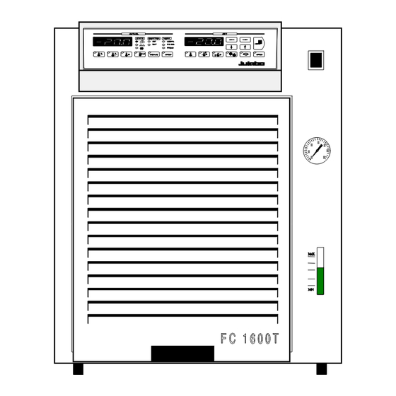
Recirculating coolers Operating controls and functional elements Mains power switch, illuminated Filling funnel Drain tubing Drain tap Filling level indication Pump pressure gauge MULTI-Display temperature indication (LED 1 + LED 2) Indicator lights Alarm Temp. = Keypad control mode Control Heating = Remote control mode Cooling... - Page 16 Operating controls and functional elements Keys for actual values (LED 1) Key - Indication of feed temperature Key - Indication of return temperature Key - Indication of safety temperature Key - Indication of actual temperature of external sensor The "MENUE" key is not required for normal operating The key "SPEC"...
- Page 17 Recirculating coolers Rear 12.1 Pump connector: Feed 12.2 Pump connector: Return Overflow port for bath tank Connectors for solenoid valves Mains power cable with plug 16.2 16.1 12.1 12.2 Only for water cooled models: 16.1 Cooling water OUTLET 16.2 Cooling water INLET...
-
Page 18: Operation
Operation Operation 5.1. Preparations • Place the unit in an upright position. • The place of installation should be large enough and provide sufficient air ventilation to ensure the room does not warm up excessively because of the heat the instrument rejects to the environment. (Max. permissible ambient temperature: 35 °C). -
Page 19: Return Flow Safety Device
Recirculating coolers Notice: Cooling water circuit Risk of oil leaking from the cooling circuit (compressor) of the recirculating cooler into the cooling water in case of a fault in the circuit! Observe the laws and regulations of the water distribution company valid in the location where the unit is operated. -
Page 20: Bath Fluids
Bath fluids Caution: No liability for use of other bath liquids! Please contact JULABO before using other than recommended bath fluids. JULABO takes no responsibility for damages caused by the selection of an unsuitable bath fluid Do not use alcohols. Water: The quality of water depends on local conditions. -
Page 21: Power Connection
Recirculating coolers 5.5. Power connection Caution: • Only connect the unit to a power socket with earthing contact (PE – protective earth)! We disclaim all liability for damage caused by incorrect line voltages! • The power supply plug serves as safe disconnecting device from the line and must be always easily accessible. -
Page 22: Draining
Operation 5.7. Draining Notice: Do not drain the bath fluid while it is hot or cold! Check the temperature of the bath fluid prior to draining (by switching the unit on for a short moment, for example). Store and dispose of the used bath fluid according to the environmental protection laws. -
Page 23: Connecting An External Sensor
Recirculating coolers 5.8. Connecting an external sensor Connect an external temperature sensor for measuring and controlling the temperature directly in the external system. (Control mode - see page 41). ACTUAL Connect a Pt100 sensor (Order No. 8 981 003) MA X M+R Adapter with Pt100 sensor MI N (Order No. -
Page 24: Manual Operation
Manual operation Manual operation 6.1. Switching on Turn on the mains power switch (1.). An illuminated switch indicates the unit is on. The unit performs a self-test. All segments of the ACTUAL 4-digit MULTI-DISPLAY (LED 1 + LED 2) and all indicator lights will illuminate. -
Page 25: Automatic / Non-Automatic Start Mode
Automatic / non-automatic start mode NOTE: The recirculating cooler has been configured and supplied by JULABO according to N.A.M.U.R. recommendations. This means for the start mode, that the unit must enter a safe operating state after a power failure (non-automatic start mode). This safe operating state is indicated by „OFF“... -
Page 26: Setting The Setpoint Temperatures
Manual operation 6.3. Setting the setpoint temperatures Set the setpoints before or after starting the unit. Press the setpoint keys (E, F, G, H) to set a value and press the Enter key to store the value. The values will stay in memory when the recirculating cooler is powered down. -
Page 27: Setting The Control Ratio For Feed/Return Flow Temperature
Recirculating coolers 6.3.2. Setting the control ratio for feed/return flow temperature In respect to the values for feed and return -0.5°C +0.5°C temperature and the factor set with the key "H" an almost constant temperature value may be maintained in the external system. The control function quickly responds to changing conditions 20°C 21°C... -
Page 28: Setting The Safety Temperatures
Manual operation 6.3.3. Setting the safety temperatures This safety function is independent of the control circuit. Press the desired setpoint key (F, G). Follow the instructions under section 6.3.1. page 26 Recommendation: Set the high temperature limit at least 5 K above the actual bath temperature. -
Page 29: Pid Control Parameters
Recirculating coolers 6.4. PID control parameters For internal and external control two separate parameter sets are available. The PID control parameters can be adapted to the requirements of the controlled member. The values are preserved after switching off the recirculating cooler. •... - Page 30 Manual operation With the parameters HL (High Limit) and LL (Low Limit) the temperature of the internal bath is limited in case of external control. So, especially for big consumers, a great overshoot resp. undershoot of the internal temperature is avoided. Effect of the limitation of the internal bath temperature: Without limitation...
- Page 31 Recirculating coolers Optimization instructions for the PID control parameters: The heat-up curve reveals inappropriate control settings optimum setting Inappropriate settings may produce the following heat-up curves: Xp too low Tv/Tn too low Tv too high...
-
Page 32: Trouble Shooting Guide
Trouble shooting guide Trouble shooting guide Whenever the microprocessor electronics registers a failure, an alarm is triggered and a complete shutdown is performed. The alarm light illuminates and an audible signal is triggered. An error message appears on the MULTI- ACTUAL DISPLAY (LED 2). -
Page 33: Other Error Messages
Recirculating coolers 7.1. Other error messages Incorrect/invalid entry. Value too small or too ACTUAL large, or function not available. Under menu item E _ Sb the parameter is set to 1, and the connection between Pin 2 and Pin 3 of the stand-by connector is interrupted (see page 35). - Page 34 Electrical connections Alarm output (M) This potential-free change-over contact is activated in case of an alarm. Pins 2 and 3 are connected under the following conditions: - alarm - status "OFF" and "rOFF" - mains switch "off" Switching capacity max. 30 W / 40 VA Switching voltage max.
- Page 35 Recirculating coolers Stand-by input (L) Pin assignment: Signal not used 5 V / DC Activate the stand-by input: Under menu item E _ Sb, set the parameter to 1 (see page 40). Connect an external contact 'AK' (e.g. for emergency switch-off) or an alarm contact of the superordinated application system.
-
Page 36: Remote Control
Remote control Remote control 9.1. Communication with a PC or data system For remote control, under the menu item OP ACTUAL (Operating mode) set the parameter to 1. The message "rOFF" appears on the display. In general, the computer (master) sends commands to the recirculating cooler (slave). - Page 37 Recirculating coolers Command Parameter Response of recirculating cooler out_mode_05 Stop the recirculating cooler = rOFF out_mode_05 Start the recirculating cooler in_mode_05 Ask for actual condition (Start/Stop) out_sp_00 xx.x Set working temperature value in_sp_00 Ask for working temperature value in_sp_01 Ask for high temperature value in_sp_02 Ask for low temperature value out_sp_03...
-
Page 38: Status Messages
Remote control 9.3. Status messages Message Description - Recirculating cooler ... 00 MANUAL STOP ... in condition "OFF" (LOCAL) 01 MANUAL START ... in keypad control mode (LOCAL) 02 REMOTE STOP ... in condition "rOFF" (RS 232) 04 REMOTE START ... -
Page 39: Menu Functions
Recirculating coolers 10. Menu functions Set the parameters for the recirculating cooler via the configuration or calibration level. 10.1. Selecting/exiting the configuration level Simultaneously press the "MENUE" key (4.2) + 1x the edit key " " to select the configuration level + 1x the edit key "... -
Page 40: Adjustable Parameters
Menu functions 10.3. Adjustable parameters Set the parameters for the following menu items in the configuration level: OP - Operating mode ACTUAL = Keypad control = Remote control via RS 232 HAnd - Handshake of the serial interface ACTUAL = XOn/XOff, software handshake = RTS/CTS, hardware handshake * PAr - Parity bits of the serial interface ACTUAL... -
Page 41: Selecting/Exiting The Calibration Level
Recirculating coolers Attention: The following menu point Cont is only adjustable via the configuration level if the status is „OFF“. On a unit which is switched on this status is reached by switching on/off at the mains switch (1). Cont - Control mode ACTUAL = internal control = external control (with an external... - Page 42 Menu functions Ad ¯ P - Calibration of programmer input: ACTUAL Highest value = 80 °C Ad _ P - Calibration of programmer input: ACTUAL Lowest value = -20 °C Calibration procedure: In the configuration level, set the programmer ACTUAL input type to allow control via an external programmer.
- Page 43 Recirculating coolers Set the external programmer to the lowest temperature value. In the calibration level, select the item Ad _ P and ACTUAL set the lowest temperature value (example: -20 °C). Press the setpoint key (E). Follow the instructions under section 6.3.1. page 26.
-
Page 44: Cleaning / Repairing The Unit
The recirculating cooler is designed for continuous operation under normal conditions. Periodic maintenance is not required. The tank should be filled only with a bath fluid recommended by JULABO. To avoid contamination, it is essential to change the bath fluid from time to time. Repairs:... -
Page 45: Warranty Provisions
Recirculating coolers 12. WARRANTY PROVISIONS The following Warranty Provisions shall apply to products sold in North America by Julabo (“Seller”) to the entity shown as buyer (“Buyer”) on Seller’s invoice. Initial Warranty. Upon Seller’s receipt of payment in full for the products and subject to Buyer’s... - Page 46 WARRANTY PROVISIONS MANUFACTURING COSTS, LOST PROFITS, GOODWILL, OR ANY OTHER SPECIAL, INDIRECT, PUNITIVE, INCIDENTAL OR CONSEQUENTIAL DAMAGES TO BUYER OR ANY THIRD PARTY AND ALL SUCH DAMAGES ARE HEREBY DISCLAIMED. Assignment. Buyer shall not assign any of its rights or obligations hereunder without the prior written approval of Seller;...
Need help?
Do you have a question about the FC1200S and is the answer not in the manual?
Questions and answers