Sign In
Upload
Download
Table of Contents
Contents
Add to my manuals
Delete from my manuals
Share
URL of this page:
HTML Link:
Bookmark this page
Add
Manual will be automatically added to "My Manuals"
Print this page
×
Bookmark added
×
Added to my manuals
Manuals
Brands
Julabo Manuals
Air Conditioner
FL300
Operating manual
Julabo FL300 Operating Manual
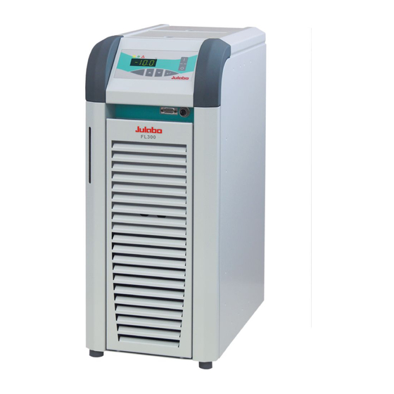
Recirculating cooler
Hide thumbs
1
2
3
Table Of Contents
4
5
6
7
8
9
10
11
12
13
14
15
16
17
18
19
20
21
22
23
24
25
26
27
28
29
30
31
32
33
34
35
36
37
38
39
40
41
42
43
44
45
46
47
48
page
of
48
Go
/
48
Contents
Table of Contents
Troubleshooting
Bookmarks
Table of Contents
Operating Manual
Table of Contents
1 Intended Use
Description
2 Operator Responsibility - Safety Instructions
Disposal
3 Technical Specifications
4 Safety Notes for the User
Explanation of Safety Notes
Explanation of Other Notes
Safety Instructions
5 Installation
Tubing
6 Operating Controls and Functional Elements
7 Operating Procedures
Bath Fluids
Power Connection
Filling
Switching on / Start - Stop
Setting the Temperatures
Autostart on / off
Remote Control: Activate - Deactivate
8 Safety Installations
Excess Temperature Protection
Low Level Protection
9 Troubleshooting Guide / Error Messages
10 Electrical Connections
11 Remote Control
Setup for Remote Control
Communication with a PC or a Superordinated Data System
List of Commands
Status Messages
Error Messages
12 Cleaning / Repairing the Unit
13 Adequate Storing of Operating Manual
14 Draining
15 Warranty Conditions
Advertisement
Quick Links
1
Operating Manual
2
Technical Specifications
3
Bath Fluids
4
Filling
5
Switching on / Start - Stop
6
Troubleshooting Guide / Error Messages
7
Cleaning / Repairing the Unit
Download this manual
Operating manual
Recirculating Coolers
RS232
ALARM
FL300
FL300
FL601
English
19514818-V1.doc
17.01.13
Table of
Contents
Previous
Page
Next
Page
1
2
3
4
5
Advertisement
Table of Contents
Need help?
Do you have a question about the FL300 and is the answer not in the manual?
Ask a question
Questions and answers
Related Manuals for Julabo FL300
Air Conditioner Julabo FL601 Operating Manual
Recirculating cooler (48 pages)
Air Conditioner Julabo FL7006 Operating Manual
(34 pages)
Air Conditioner Julabo FC1200S Operating Manual
Recirculating coolers (46 pages)
Air Conditioner Julabo FC600 Operating Manual
Recirculating coolers (37 pages)
Air Conditioner Julabo F250 Operating Manual
Recirculating cooler (32 pages)
Air Conditioner Julabo FL20006 Operating Manual
Recirculating coolers (32 pages)
Air Conditioner Julabo FLW20006 Operating Manual
Recirculating coolers (32 pages)
Air Conditioner Julabo F12-ED Operating Manual
Refrigerated and heating circulators (27 pages)
Air Conditioner Julabo F25-MC Operating Manual
Refrigerated and heating circulators (58 pages)
Air Conditioner Julabo F25-HE Original Operating Manual
Refrigerated and heating circulators (82 pages)
Air Conditioner Julabo FP40-HE Original Operating Manual
Refrigerated and heating circulators (82 pages)
Air Conditioner Julabo AWC100 Operating Instructions Manual
Compact recirculating cooler (16 pages)
Air Conditioner Julabo ME-31A Operating Manual
(63 pages)
This manual is also suitable for:
Fl601
Table of Contents
Print
Rename the bookmark
Delete bookmark?
Delete from my manuals?
Login
Sign In
OR
Sign in with Facebook
Sign in with Google
Upload manual
Upload from disk
Upload from URL


Need help?
Do you have a question about the FL300 and is the answer not in the manual?
Questions and answers