
Related Manuals for Bunn TU5Q


Summary of Contents for Bunn TU5Q
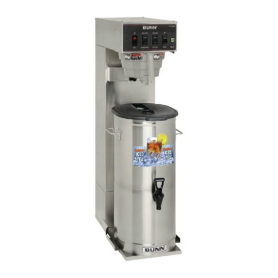
- Page 1 TU5Q OPERATING & SERVICE MANUAL BUNN-O-MATIC CORPORATION POST OFFICE BOX 3227 SPRINGFIELD, ILLINOIS 62708-3227 PHONE: (217) 529-6601 FAX: (217) 529-6644 10777.0000C 05/12 © 1994 Bunn-O-Matic Corporation...
-
Page 2: Warranty
AS SPECIFIED HEREIN, TO REPAIR, REPLACEMENT OR REFUND. In no event shall BUNN be liable for any other damage or loss, including, but not limited to, lost profi ts, lost sales, loss of use of equipment, claims of Buyer’s customers, cost of capital, cost of down time, cost of substitute equipment, facilities or services, or any other special, incidental or consequential damages. -
Page 3: Table Of Contents
CONTENTS Introduction ..............2 Warranty ..............2 User Notices .............3 Electrical Requirements ..........4 Plumbing Requirements ...........4 Initial Set-Up .............5 Operating Controls ............6 Cleaning ..............6 Tea Brewing ..............6 Troubleshooting ............7 Service ..............12 Wiring Diagrams .............23 INTRODUCTION This equipment will brew a three or fi ve-gallon batch of fresh tea into an awaiting dispenser. The tea will be dispensed at approximately room temperature to conserve ice. -
Page 4: User Notices
BEFORE BUYING OR USING THIS PRODUCT THIS APPLIANCE IS HEATED WHENEVER CONNECTED TO A POWER SOURCE 00831.0000F 3/98 ©1998 BUNN-O-MATIC CORPORATION As directed in the International Plumbing Code of the International Code Council and the Food Code Manual of the Food and Drug Administration (FDA), #00656.0001... -
Page 5: Electrical Requirements
" water supply line. A tight coil of copper tubing in the water line will facilitate moving the brewer to clean the countertop. Bunn-O-Matic does not recommend the use of a saddle valve to install the brewer. The size and shape of the hole made in the supply line by this type of device may restrict water fl ow. -
Page 6: Initial Set-Up
INITIAL SET-UP CAUTION - The brewer must be disconnected from the power source throughout the Initial Set-Up, except when specifi ed in the instructions. 1. Remove the top lid from the brewer. 2. Rotate the control thermostat knob fully counterclockwise to the "OFF" position. Set the three-gallon timer knob at 4 minutes, the fi... -
Page 7: Operating Controls
TEA BREWING 1. Begin each brew cycle with a clean empty brew funnel and server. (Be sure the server lid doesn’t interfere with the fl ow of dilution water.) 2. Insert a BUNN ® fi lter into the funnel. 3. Pour the packet of loose fresh tea leaves into the fi lter. Approximately one ounce is recommended for each gallon of fi... -
Page 8: Troubleshooting
TROUBLESHOOTING A troubleshooting guide is provided to suggest probable causes and remedies for the most likely problems encountered. If the problem remains after exhausting the troubleshooting steps, contact the Bunn-O-Matic Technical Service Department. • Inspection, testing, and repair of electrical equipment should be performed only by qualifi ed service person- nel. - Page 9 TROUBLESHOOTING (cont.) PROBLEM PROBABLE CAUSE REMEDY 6. Brew Timer Brew cycle will not start (cont.) Refer to Service - Brew Timer for testing procedures. See page 15 7. Brew Solenoid Valve Refer to Service - Brew Solenoid Valve for testing procedures. See page 14 1.
- Page 10 TROUBLESHOOTING (cont.) PROBLEM PROBABLE CAUSE REMEDY Inconsistent beverage level in 1. Syphon System The brewer must be level or slightly dispenser lower in front to syphon properly. 2. Lime Build-up Inspect the tank assembly for ex- CAUTION - Tank and tank compo- cessive lime deposits.
- Page 11 3. Brew Solenoid Valve and clean any obstruction. Rebuild or replace the valve if necessary. See page 14 Weak beverage BUNN ® paper fi lters must be used 1. Filter Type for proper extraction. A suffi cient quantity of fresh, loose 2.
- Page 12 REMEDY PROBLEM PROBABLE CAUSE ® Weak beverage (cont.) 4. Funnel Loading The BUNN paper fi lter must be centered in the funnel and the bed of tea leaves leveled by gentle shaking. 5. Water Temperature Place an empty funnel on an empty dispenser beneath the sprayhead.
-
Page 13: Service
SERVICE This section provides procedures for testing and replacing various major components used in this brewer should service become necessary. Refer to Troubleshooting for assistance in determining the cause of any problem. WARNING - Inspection, testing, and repair of electri- cal equipment should be performed only by qualifi... -
Page 14: Batch Selector Switch
SERVICE (cont.) BATCH SELECTOR SWITCH 5. Select the 5-gallon setting. 6. Check for continuity between the terminals where the orange and yellow wires connect to the switch. Continuity should be present. If continuity is present as described, reconnect the wires, the switch is operating properly. If continuity is not present as described, replace the switch. -
Page 15: Brew Solenoid Valve
SERVICE (cont.) If continuity is present as described, reconnect the white/violet from the brew timer and white/green wire BREW SOLENOID VALVE from the brew timer. If continuity is not present as described, replace the solenoid valve. 6. Check the solenoid valve for coil action. Connect the brewer to the power source. -
Page 16: Brew Timer
SERVICE (cont.) If continuity is present as described, reconnect the wires to terminals TL3, TL4, & TL5 of the timer board BREW TIMER and proceed to #6. If continuity is not present as described, refer to the Wiring Diagram and check the wiring harness. 6. -
Page 17: Control Thermostat
SERVICE (cont.) a) 120 volts ac for 2-wire 120 volt models. b) 208 volts ac for 3-wire 120/208 volt models. CONTROL THERMOSTAT c) 240 volts ac for 3-wire 120/240 volt models. 8. Disconnect the brewer from the power source. If voltage is present as described, reinstall the capillary tube into the tank to the line 5.5"... -
Page 18: Dilution Solenoid Valve
SERVICE (cont.) If continuity is present as described, reconnect the white/blue wire from the dilution switch and white/ DILUTION SOLENOID VALVE green wire from the brew solenoid terminal. If continuity is not present as described, replace the solenoid valve. 6. Check the solenoid valve for coil action. Connect the brewer to the power source. -
Page 19: Dilution Switch
SERVICE (cont.) DILUTION SWITCH 5. Set Dilution switch to "NO DILUTION". 6. Check for continuity between the terminals where the white/blue and white/violet connect to the switch. Continuity should not be present. If continuity is present as described, reconnect the wires. -
Page 20: Limit Thermostat
SERVICE (cont.) white or red wire on the tank heater terminal. Con- nect the brewer to the power source. The indication LIMIT THERMOSTAT must be: a) 120 volts ac for 2-wire 120 volt models. b) 208 volts ac for 3-wire 120/208 volt models. c) 240 volts ac for 3-wire 120/240 volt models. -
Page 21: On/Off Switch
SERVICE (cont.) 5. Disconnect the brewer from the power source. ON/OFF SWITCH If voltage is present as described, proceed to #6. If voltage is not present as described, refer to the Wir- ing Diagrams and check the wiring harness. 6. Check for continuity across the center and end terminals of the bottom row when the switch is in the “ON”... -
Page 22: Start Switch
SERVICE (cont.) If continuity is present as described, reconnect the START SWITCH wires, the switch is operating properly. If continuity is not present as described, replace the switch. Removal and Replacement: 1. Remove the wires from the switch terminals. 2. Compress the clips inside the hood and gently push the switch through the opening. -
Page 23: Tank Heater
SERVICE (cont.) If continuity is not present as described, replace the TANK HEATER tank heater. NOTE- If the tank heater remains unable to heat, re- move and inspect heater for cracks in the sheath. Removal and Replacement: 1. Disconnect the black wire and the white or red wire from the tank heater terminals. -
Page 24: Wiring Diagrams
WHI/YEL 120/240 VOLTS AC 3 WIRE SINGLE PHASE 3-GAL 5-GAL BATCH SELECT 10776.0000A 12/93 © 1993 BUNN-O-MATIC CORPORATION SCHEMATIC WIRING DIAGRAM TU5Q W/SWEETENER READY INDICATOR GREEN LIMIT SW. & THERMOSTAT THERMOSTAT RED (208 OR 240V) TANK HEATER WHI (120V) OFF/ON/START...
Need help?
Do you have a question about the TU5Q and is the answer not in the manual?
Questions and answers