
Related Manuals for Lowrance M56 S/Map


Summary of Contents for Lowrance M56 S/Map
- Page 1 Pub. 988-0152-021 www.lowrance.com M56 S/Map Fish-finding Sonar & Mapping GPS Installation and Operation Instructions...
- Page 2 Copyright © 2003 Lowrance Electronics, Inc. All rights reserved. ® Lowrance is a registered trademark of Lowrance Electronics, Inc. Marine-Tex is a trademark of Illinois Tool Works Inc. Lowrance Electronics may find it necessary to change or end our policies, regulations, and special offers at any time. We reserve the right to do so without notice.
-
Page 3: Table Of Contents
Sec. 1: Read Me First! ... 1 Capabilities and Specifications: M56... 3 How your Sonar Works... 4 How your GPS Works ... 5 Introduction to GPS and WAAS ... 5 How to Use this Manual: Typographical Conventions ... 7 Sec. 2: Installation & Accessories ... 9 Preparations... - Page 4 Fish I.D. (Fish Symbols & Depths)... 51 FishReveal ... 52 FishTrack ... 54 Grayline ... 54 Overlay Data ... 55 Ping Speed & HyperScroll... 57 Reset Options ... 58 Sensitivity & Auto Sensitivity ... 59 Set Keel Offset ... 61 Sonar Color Mode ...
- Page 5 Find Distance from Point to Point ... 97 Icons... 98 Create Icon on Map ... 98 Create Icon at Current Position... 98 Delete an Icon ... 99 Navigate to an Icon... 99 Routes... 100 Create and Save a Route ... 100 Delete a Route...
- Page 6 Pop-Up Help... 123 Reset Options ... 124 Screen Contrast and Brightness... 124 Set Language ... 125 Set Local Time ... 126 Show WAAS Alarm... 126 Software Version Information... 127 Sounds and Alarm Sound Styles... 127 Track Smoothing... 128 Trail Options ... 128 Delete All Trails...
-
Page 7: Sec. 1: Read Me First
The manual is organized into 10 sections. This first section is an intro- duction to the M56 sonar and GPS. It tells you the basics you need to know before you can make the unit look around and tell you where you are, or look below the surface to find some fish. - Page 8 When you come to a sonar menu command on the unit's screen, you can look it up in the manual by skimming over the table of contents or the in- dex, or just flipping through Section 3 or scanning through the sonar op- tions in Section 4.
-
Page 9: Capabilities And Specifications: M56
Capabilities and Specifications: Display:... High-contrast Film SuperTwist LCD. Diago- Resolution:... 160 pixel x 240 pixel resolution; 38,400 total Backlighting:... LED backlit screen with multiple lighting lev- Input power:... 10 to 17 volts DC. Current drain: ... 170 ma lights off; 240 ma lights on. Case size:... -
Page 10: How Your Sonar Works
Receiver/antenna: ... Internal 12 parallel channel GPS/WAAS. Position updates: ... Every second. Position points: ... 1,000 waypoints; 1,000 event marker icons. Man Overboard:... MOB feature precisely marks man overboard Audible alarms: ... Arrival/off-course/destination passed/anchor. Graphic symbols for waypoints or event marker icons: ... -
Page 11: How Your Gps Works
The receiver amplifies this return signal, or echo, and sends it to the display, where an image of the object appears on the scrolling sonar chart. The sonar's microprocessor calculates the time lapse between the transmitted signal and echo return to determine the distance to the object. - Page 12 tion, look over this segment describing how GPS and its new companion WAAS work together to get you where you're going. The Global Positioning System (GPS) was launched July 17, 1995 by the United States Department of Defense. It was designed as a 24- hour-a-day, 365-days-a-year, all weather global navigation system for the armed forces of the U.S.
-
Page 13: How To Use This Manual: Typographical Conventions
WAAS reception, but terrain, foliage or even large man-made structures can sometimes block the WAAS signal from ground receivers. You'll find that using your GPS receiver is both easy and amazingly accurate. It’s easily the most accurate method of electronic navigation available to the general public today. - Page 14 menu command to use by finding the boldface command text. The fol- lowing paragraphs explain how to interpret the text formatting for those commands and other instructions: Arrow Keys The arrow keys control the movement of dotted cross-hair lines on your mapping screen called the cursor.
-
Page 15: Sec. 2: Installation & Accessories
Installation & Accessories Preparations You can install the sonar and GPS systems in some other order if you prefer, but we recommend this installation sequence: CAUTION: You should read over this entire installation section before drill- ing any holes in your vehicle or vessel! 1. -
Page 16: Recommended Tools And Supplies
Remember, the transducer location and installation is the most critical part of a sonar installation. Recommended Tools and supplies If you prefer the option of routing the cable through the transom, you will need a 5/8" drill bit. NOTE: The following installation types also call for these recommended tools and required supplies that you must provide (supplies listed here are not included): Transom installation... -
Page 17: How Low Should You Go
boat hulls have a flat keel pad that offers a good mounting surface. On vee hulls, try to place the transducer where the deadrise is 10° or less. Left, vee pad hull; right, vee hull. A pod style transducer is shown here, but the principle is the same for Skimmers inside a hull. -
Page 18: Shoot-Thru-Hull Vs. Transom Mounting
Transducer centerline Align transducer centerline with hull bottom. However, there are times when you may need to adjust the transducer slightly higher or lower. (The slots in the mounting brackets allow you to loosen the screws and slide the transducer up or down.) If you fre- quently lose bottom signal lock while running at high speed, the trans- ducer may be coming out of the water as you cross waves or wakes. -
Page 19: Transom Transducer Assembly And Mounting
Second, the transducer angle cannot be adjusted for the best fish arches on your sonar display. (This is not an issue for flasher-style sonars.) Lack of angle adjustment can be particularly troublesome on hulls that sit with the bow high when at rest or at slow trolling speeds. Third, a transducer CAN NOT shoot through wood and metal hulls. - Page 20 Reassemble the transducer and bracket and place them against the transom. Again, check to see if you can move the transducer so it's parallel with the ground. If you can, then go to step 3. If it doesn't, repeat step 2, but use a different alignment letter until you can place the transducer on the transom correctly.
- Page 21 Transom Position transducer mount on transom and mark mounting holes. Side view shown at left and seen from above at right. 5. Attaching transducer to transom. Remove the transducer from the bracket and re-assemble it with the cable passing through the bracket over the bolt as shown in the following figures.
-
Page 22: Trolling Motor Bracket Installation
6. Route the transducer cable through or over the transom to the sonar unit. Make sure to leave some slack in the cable at the transducer. If possible, route the transducer cable away from other wiring on the boat. Electrical noise from the engine's wiring, bilge pumps, VHF radio wires and cables, and aerators can be picked up by the sonar. -
Page 23: Transducer Orientation And Fish Arches
3. Route the transducer cable alongside the trolling motor shaft. Use plastic ties (not included) to attach the transducer cable to the troll- ing motor shaft. Make sure there is enough slack in the cable for the motor to turn freely. Route the cable to the sonar unit and the trans- ducer is ready for use. -
Page 24: Shoot-Thru-Hull Preparation And Installation
If the arch slopes up – but not back down – then the front of the trans- ducer is too high and needs to be lowered. If only the back half of the arch is printed, then the nose of the transducer is angled too far down and needs to be raised. - Page 25 Testing Determines Best Location Ideally, the shoot-thru transducer should be installed as close to the transom as possible, close to the centerline. This will give you the best performance during high speed maneuvers. Transducer location (high speed) Shoot-thru-hull transducer locations for high speed or trolling speed operation.
- Page 26 2. Next, take the transducer out of the water and place it in the water in the sump of the boat, face down. (The transducer face is shown in the figure on the following page.) Notice how the signal strength de- creases.
- Page 27 Sand this surface WARNING: Use only the epoxy available from LEI. It has been for- mulated to work with these installation procedures. Other epoxy types may be too thin or may not cure to the right consistency for optimum transducer performance. 2.
-
Page 28: Power And Cable Connections
To unit Power and transducer connections for the M56 sonar units (direct battery connection shown). If possible, keep the power cable away from other boat wiring, espe- cially the engine's wires. -
Page 29: Mounting The Sonar Unit: In-Dash Or Bracket
It can also be installed in the dash with an optional FM-6 dash-mounting kit. In-Dash Installation The following figure shows the approximate shape for in-dash mounting an M56. The in-dash adapter kit includes a template for cutting the mounting hole and complete installation instructions on instruction sheet 988-0147-631. - Page 30 ALWAYS VERIFY DIMENSIONS. Cut along this line In-dash mounting template for M56. NOTE: This figure is not printed to scale. Bracket Installation Mount the unit in any convenient location, provided there is clearance when it’s tilted for the best viewing angle. You should also make sure there is enough room behind the unit to attach the power/transducer cable.
- Page 31 [4.23] 76.9 [3.03] Front view (left) and side view (right) showing dimensions of the M56 when mounted on quick release bracket. If you wish, you can fill in the hole around the cable with a good marine sealant compound. (Some marine dealers stock cable hole covers to con- ceal the opening.)
- Page 32 Screw hole Power/transducer cable M56 quick release mounting bracket. Slots in the base allow routing the cable from beneath the mount. Attach the unit to the bracket by first connecting the power/transducer cable. Then, hold the sonar unit vertically and slide it onto the bracket from above.
-
Page 33: Portable Sonar Installation
The power pack and portable transducers expand the uses for your so- nar. You can use your M56 sonar unit on your boat or take it to the dock, on a float tube, on an ice fishing trip or use it as a second sonar in a friend's boat. - Page 34 NOTE: When the unit is not in use, we recommend you unplug the power connector to reduce the possibility of corrosion or battery drain. When you store the unit, always remove the batteries because dead batteries can leak and corrode the contacts. After installing the batteries, plug the cable's power connector into the socket on the battery compartment cover.
-
Page 35: Portable Transducer Assembly
If the batteries do lose a charge, you can sometimes restore them by placing them in a warm room or car interior. A better way is to replace them with batteries that have been kept warm. WARNING: Never heat the batteries over an open flame or direct hot air onto them. - Page 36 Hull Portable transducer installed on boat transom. NOTE: For optimum operation, the portable transducer should be adjusted so that it is parallel to the ground. For more information on this, see the earlier segment on Transducer Orientation and Fish Arches. Now that you have your unit installed, move on to Sec.
-
Page 37: Sec. 3: Basic Sonar Operation
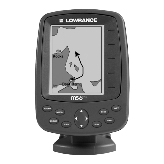
Numbers in the photo correspond to key ex- planations below: Lowrance M56 Sonar, front view, showing screen and keyboard. (A close-up of the keyboard can be found at the beginning of Sec. 6) 1. PWR (Power & Light) – The PWR key turns the unit on and off and activates the backlight. -
Page 38: Memory
4. ARROW KEYS – These keys are used to navigate through the menus, make menu selections, move the plotter cursor and sonar chart cursor and enter data. 5. ENT (Enter) – This key allows you to save data, accept values or execute menu commands. -
Page 39: Sonar Menu
Sonar Setup command: sets various sonar options. GPS Setup command: sets various GPS receiver options. System Setup command: sets general configuration options. Sun/Moon Calculations command: finds the rising and setting time of the sun and the moon. - Page 40 time. You run a command by using ↑ or ↓ to highlight the command and then pressing . To clear the menu screen and return to the Page display, press EXIT Sonar Page Menu. Most of these functions are discussed in Sec.
- Page 41 • Ping Speed command: sets the rate at which sonar pings are made. Pages The M56 has four major Sonar display options. They are the Full Sonar Chart, Split Zoom Sonar Chart, Digital Data and Flasher. You access the various display modes by pressing the pressing →...
- Page 42 Sonar chart display options (from left) full sonar chart and split zoom. Sonar chart display options (from left) digital data and flasher. You can customize how the Sonar Page pictures and other data are dis- played in many ways. We'll discuss all of those features and options in the Advanced Sonar Operation section, but to show you how easy the sonar unit is to operate, the following page contains a simplified, 10- step quick reference that will cover most fish finding situations.
-
Page 43: Basic Sonar Quick Reference
Basic Sonar Quick Reference 1. Mount the transducer and unit. Connect the unit to electric power and the transducer. 2. Launch your boat. 3. To turn on the unit, press and release 4. Head for your fishing grounds. Your unit automatically displays digi- tal depth and surface water temperature in the corner of the screen. -
Page 44: Sonar Operations
Sonar Operations As you can see from the quick reference on the previous page, basic operation is pretty easy, right out of the box. If you are a sonar novice, try operating the unit with the factory defaults until you get a feel for how it's working. As you're learning the basics, there is one setting you might want to tinker with from time to time —... - Page 45 You can change the sensitivity level whether you are in Auto Sensitiv- ity mode or Manual Sensitivity mode. The adjustment method works the same in both modes, but it gives you slightly different results. Adjusting sensitivity in Auto Sensitivity Mode is similar to manually ad- justing a car's speed with the accelerator pedal while cruise control is on.
-
Page 46: Fish Symbols Vs. Full Sonar Chart
NOTE: If you want to change the sensitivity in Manual Mode, first turn off Auto Sensitivity: from the Sonar Page, press |↑ to ENSITIVITY sensitivity setting. When it's set at the desired level, press Important Tip: While you are experimenting and learning, it's possible to scramble the settings so that the sonar picture disappears from your screen. -
Page 47: Other Free Training Aids
Other Free Training Aids The following section discusses Fish I.D., fish alarms and other fea- tures in greater detail. If you or a friend has Internet access, you can also learn more about interpreting what you see on your sonar screen. Visit our web site, . - Page 48 Notes...
-
Page 49: Sec. 4: Sonar Options & Other Features
Section 4: Sonar Options & Other Features Material in this section is arranged in alphabetical order. ASP (Advanced Signal Processing) The ASP feature is a noise rejection system built into the sonar unit that constantly evaluates the effects of boat speed, water conditions and interference. -
Page 50: Alarms
3. Press ↓ or ↑ to select a setting, then press 4. To return to the previous page, press Alarms This unit has three different types of sonar alarms. The first is a Fish Alarm. It sounds when the Fish I.D. feature determines that an echo is a fish. -
Page 51: Zone Alarm
3. Press ↑ or ↓ until the depth is correct, then press 4. Press ← to HALLOW 5. To turn off the alarm, press ONAR LARMS To switch to a different depth setting, open the Sonar Alarms menu and repeat the instructions in step 3 above. To adjust and turn on the deep alarm: 1. -
Page 52: Fish Alarm
3. To set the upper boundary for the Zone Alarm, use ← or→ to select , then press ↑ or ↓ to move the top of the bar to the desired depth. PPER 4. To set the lower boundary for the Zone Alarm, use ← or→ to select , then press ↑... -
Page 53: Chart Speed
Chart Speed The rate that echoes scroll across the screen is called the chart speed. The default is maximum; we recommend that you leave the speed set there for virtually all fishing conditions. However, you might consider experimenting with chart speed when you are stationary or drifting very slowly. -
Page 54: Depth Range - Automatic
At left, Sonar Page menu with Depth Cursor command selected. At right, sonar chart with the depth cursor active. The line indicates the The cursor can be moved to any location on the screen, letting you pin- point the depth of a target. 1. -
Page 55: Depth Range - Manual
2. The Depth Range Control Scale appears. Press ↑ or ↓ to select a dif- ferent depth range. A dark bar highlights the selected range. Range numbers in gray cannot be selected. 3. When the new range is selected, press Depth Range - Manual You have complete control over the range when the unit is in the man- ual mode. - Page 56 At left, Sonar Page Menu with Upper and Lower Limits command se- lected. At right, Sonar Chart Limits menu, with Upper Limit selected. To change the upper and lower limits: 1. From the Sonar Page, press The Sonar Chart Limits menu appears, with Upper Limit selected. 2.
-
Page 57: Fastrack
FasTrack This feature automatically converts all echoes to short horizontal lines on the display's far right side. The graph on the rest of the screen con- tinues to operate normally. FasTrack gives you a rapid update of condi- tions directly under the boat. This makes it useful for ice fishing, or when you're fishing at anchor. -
Page 58: Fishreveal
Does that mean Fish I.D. is broken? No — the feature is simply inter- preting sonar returns in a specific way to help take some of the work out of reading the screen. Remember: Fish I.D. is one of the many tools we provide so you can analyze your sonar returns for maximum fish finding information. - Page 59 white. Also note that when using FishReveal, we recommend that you turn off Auto Sensitivity and turn up Sensitivity to near maximum. Sonar Color Mode command with FishReveal selected. To turn FishReveal on: 1. From the Sonar Page, press 2. Press ↓ to ONAR 3.
-
Page 60: Fishtrack
FishTrack The FishTrack feature shows the depth of a fish symbol when it ap- pears on the display. This lets you accurately gauge the depth of tar- gets. This feature is available only when the Fish I.D. feature is on. The default setting for FishTrack is off. -
Page 61: Overlay Data
At left, Sonar Page menu with Grayline command selected. At right, the Grayline control bar. To adjust the Grayline level: 1. From the Sonar Page, press |↓ to MENU RAYLINE 2. The Grayline Control Bar appears. Press ↓ to decrease Grayline; press ↑... - Page 62 When selected, a check mark appears beside the data type. (If you wish, you may now use ↓ or ↑ to select other Data Types for display.) Data list showing "Ground Speed" turned on to display on Sonar Page. 3. To return to the previous page, press To turn off displayed data: 1.
-
Page 63: Ping Speed & Hyperscroll
Sonar chart with Overlay Data turned on. This example shows Depth, Water Temperature and the Ground Speed of the boat. Ping Speed & HyperScroll Ping Speed controls the rate at which the transmitter and transducer broadcast sonar sound waves — pings — into the water. The unit has a default ping speed of 50 percent. -
Page 64: Reset Options
At left, Sonar Menu with Ping Speed command selected. Ping Speed Control Bar, right, at default setting. To change Ping Speed: 1. From the Sonar Page, press 2. The Ping Speed Control Bar appears. Press ↑ to increase ping speed; press ↓... -
Page 65: Sensitivity & Auto Sensitivity
1. Press |↓ to |↓ to MENU MENU YSTEM ETUP ESET PTIONS 2. Press ↑ or ↓ to 3. All the menus are cleared and all options are returned to the factory settings. System Menu with Reset Options command selected. Sensitivity &... - Page 66 and boat wakes can create enough tiny air bubbles to clutter much of the water column. In that case, a decrease in sensitivity is indicated to reduce some of the clutter. The control bar used to adjust sensitivity up or down is the same whether the unit is in the automatic or manual mode.
-
Page 67: Set Keel Offset
NOTE: To return to the original factory setting for Auto Sensitivity, see the entry in this section on Reset Options. If sensitivity is in manual mode, the Reset Options command will switch back to Auto and re- set the factory setting at the same time. Tip: For quicker sensitivity adjustments, try leaving the Sensitivity Control Bar on the screen as the chart scrolls. -
Page 68: Sonar Color Mode
3. Press ↓ or ↑ to Mode Name| 4. Press EXIT EXIT Sonar Page & Sonar Chart Display Options The M56 offers four Sonar chart display options. To choose among them, press to clear any menus, then press EXIT row keys to select the desired mode. -
Page 69: Split Zoom Sonar Chart
Full Sonar Chart. The Overlay Data (depth and water temperature) are each set to a different text size. Split Zoom Sonar Chart A split chart shows the underwater world from the surface to the bot- tom on the right side of the screen. The left side shows an enlarged ver- sion of the right side. -
Page 70: Flasher
Flasher The Flasher page represents a flasher style sonar. A circular dial shows all returning echoes at a high screen refresh rate. It uses the Grayline feature to show weaker targets as lighter colors. The bottom depth is also shown as a black bar across the outer circle. Bottom signal Sonar Simulator This unit has a built-in simulator that lets you run it as if you were on... -
Page 71: Stop Chart
Stop Chart If you are running multiple units on a boat, there are times when you may want to turn off the sonar. This command turns off the sonar and stops the chart from scrolling. Sonar restarts automatically each time you turn on your unit. -
Page 72: Upper And Lower Limits
Sonar Features menu with Surface Clarity selected. 2. Press ↑ or ↓ to select clarity level| Upper and Lower Limits See the entry in this section for Depth Range - Upper and Lower Limits Zoom & Zoom Bar "Zooming" the display is used to enlarge small detail, fish signals and the bottom with its associated structure. -
Page 73: Zoom Pan
At left, Sonar Page, normal view. Center, same view zoomed to 2X. Right, same view zoomed to 4X Zoom Pan Your unit has the handy ability to quickly zoom in on any portion of the water column with just the touch of an arrow key. The Zoom Pan feature lets you rapidly move the zoomed area up and down to different depths. - Page 74 Notes...
-
Page 75: Sec. 5: Sonar Troubleshooting
Section 5: Sonar Troubleshooting If your unit is not working, or if you need technical help, please use the following troubleshooting section before contacting the factory customer service department. It may save you the trouble of returning your unit for repair. For contact information, refer to the last page, just inside the back cover of this manual. - Page 76 3. The water may be deeper than the sonar's ability to find the bottom. If the sonar can't find the bottom signal while it's in the automatic mode, the digital sonar display will flash continuously. It may change the range to limits far greater than the water you are in. If this hap- pens, place the unit in the manual mode, then change the range to a realistic one, (for example, 0-100 feet) and increase the sensitivity.
- Page 77 To eliminate or minimize the effects of electrical noise, first try to de- termine the cause. With the boat at rest in the water, the first thing you should do is turn all electrical equipment on the boat off. Make sure the engine is also off.
- Page 78 Notes...
-
Page 79: Sec. 6: Basic Gps Operations
GPS Operations, will discuss other more advanced functions and utili- ties. Material in Sec. 7 is arranged in alphabetical order. Before you turn on the M56 and find where you are, it's a good idea to learn about the different keys, the four GPS Page screens and how they all work together. -
Page 80: Power/Lights (Turn Unit On And Off)
The M56 has a Main Menu, which contains some function commands and some setup option commands. The tutorial lessons in this section will deal only with functions, the basic commands that make the M56 do something. The unit will work fine for these lessons right out of the box with the factory default settings. - Page 81 Sonar Setup command: sets various sonar options. GPS Setup command: sets various GPS receiver options. System Setup command: sets general configuration options. Sun/Moon Calculations command: finds the rising and setting time of the sun and the moon.
-
Page 82: Sonar Page
Sonar Page: Press Satellite Status Page The Satellite Status GPS Page, shown in the following images, provides detailed information on the status of the M56's satellite lock-on and position acquisition. To get to the Satellite Status Page: Press |↑ or ↓ to |←... - Page 83 You can use this to see which satellites are obstructed by obstacles in your immediate area if the unit is facing north. The GPS receiver is tracking satellites those satellites whose numbers ap- pear in gray on the circular chart. The receiver hasn't locked onto a satel- lite if the number is black, therefore it isn't being used to solve the position.
-
Page 84: Navigation Page
Navigation Page This screen has a compass rose that not only shows your direction of travel, but also the direction to a selected waypoint. To get to the Navi- gation Page: Press The navigation screen looks like the one below when you're not navi- gating to a waypoint or following a route or trail. - Page 85 Speed instead. Closing Speed is also known as velocity made good. It's the speed that you're making toward the waypoint. For instructions, see the Customize Page Displays entry in Sec. 8.) Current track or heading, shown in degrees Cross track error range (off course indicator)
-
Page 86: Full Map Page
A circular symbol depicting your destination (waypoint) appears on the screen as you approach the waypoint, as shown on the screen in the previous figure. Travel Time is the time that it will take to reach your destination at your present closing speed. (You can also customize the time window to show Arrival Time instead. - Page 87 The following page contains a 12-step quick reference for the most basic GPS operations. If you don't want to carry the manual with you as you practice with the M56, you might consider photocopying this quick ref- erence page and tucking it into your pocket.
-
Page 88: Gps Quick Reference
1. Install the unit. (See complete installation details beginning on page 9.) 2. To turn on the M56, press and release 3. Opening screen displays the moving map at the 4,000 mile zoom range. -
Page 89: Find Your Current Position
Find Your Current Position Finding your current position is as simple as turning the unit on. Un- der clear sky conditions, the unit automatically searches for satellites and calculates its position in approximately one minute or less. NOTE: "Clear sky" means open sky, unobstructed by terrain, dense foliage or structures. -
Page 90: Selecting Any Map Item With The Cursor
Distance measured by cursor Cursor line The selected wreck (the Empress) to the southeast is 12.55 miles away. Selecting Any Map Item With the Cursor 1. Use the zoom keys and the arrow keys to move around the map and find the item you wish to select. - Page 91 Step 1. Step 3. Sequence for setting a waypoint. Step 1: while traveling, quickly press WPT twice to call up Find Waypoint screen (seen in Step 2) and set a point. Step 3: a message says the waypoint has been saved. Step 4: ve- hicle continues on its way;...
-
Page 92: Navigate To A Waypoint
2. Press name with a sequential number, such as "waypoint 001." The waypoint symbol and number appear on the map. Create Waypoint by Entering a Position 1. Press |→ to 2. Press ↓ to NTERED 3. Press ↓ to ATITUDE change the first character, then press →... -
Page 93: Set Man Overboard (Mob) Waypoint
Course line (dotted) Off course range, set at 0.20 mile Navigation Page, navigating toward waypoint 001 and leaving a trail. Set Man Overboard (MOB) Waypoint One of boating's most terrifying events is having a friend or family member fall overboard. This situation can be deadly on any body of wa- ter —... -
Page 94: Navigate To Cursor Position On Map
Navigating to Man Overboard: "Man Overboard activated" message shown at left. The Navigation Page is shown in the center and Map Page is shown at right. The victim is astern of the vessel; the GPS shows which direction to steer to for the rescue. The man overboard position is also stored in the waypoint list for future reference. - Page 95 Navigate to cursor. In this example, the cursor has selected the town of Oologah, Oklahoma. 3. Press and the M56 will begin navigating to the cursor MENU location. The Map Page will display a dotted line from your current position to the cursor position.
-
Page 96: Navigate To A Map Place
. The M56 stops showing navigation information. Creating and Saving a Trail A trail, or plot trail, is a string of position points plotted by the M56 as you travel. It's a travel history, a record of the path you have taken. - Page 97 Visible Active symbol symbol Sequence for saving a trail and beginning a new one. At left, My Trails command. Center, the Trails Menu. The arrow to the right of Trail 3 indicates the trail is "active," and the check to the left indicates the trail is visible on the map display.
-
Page 98: Displaying A Saved Trail
You can save and recall up to 10 different plot trails. Tip: Another quick way to stop recording one trail and begin a new one is to use the New Trail command: Press |→ to RAILS Caution: You also have the option of completely turning off trail record- ing, under the trail Options command. - Page 99 If you are already located at or near the beginning of your trail, the arrival alarm will go off as soon as you hit Enter. Just press clear the alarm and proceed. 5. Now, begin moving and follow your M56. 6. When you reach your destination, be sure to cancel your navigation: press |↓...
- Page 100 Figure 1. Figure 2. Figure 4. Figure 3. Navigate a trail menu sequence: Fig. 1, My Trails command. Fig. 2, Trails Menu. Fig. 3, Edit Trail Menu. Fig. 4, Edit Route Menu with Navigate Route command highlighted for Trail 1. A trail is always con- verted to a "route"...
- Page 101 3 and must turn southeast to follow the trail. Arri- val alarm goes off and bearing arrow swings around to say turn right (south), toward the next waypoint, trail point 4. The M56 now shows navigation information to point 4, which is 0.55 miles away.
-
Page 102: Cancel Navigation
If you are already located at or near the end of your trail, the arri- val alarm will go off as soon as you hit Enter. Just press clear the alarm and proceed. 5. Now, begin moving and follow your M56. 6. When you reach your destination, be sure to cancel your navigation: press |↓... -
Page 103: Sec. 7: Advanced Gps Operations
Advanced GPS Operations Find Distance From Current Position To Another Location 1. While on the Map Page press: 2. Center your cursor over the position you want to find the distance to. A rubber band line appears, connecting your current position to the cursor's location. -
Page 104: Icons
They can be placed on the map screen, saved and re- called later for navigation purposes. These are sometimes referred to as event marker icons. The M56 has 42 different symbols you can pick from when creating an icon. -
Page 105: Delete An Icon
Delete an Icon You can delete all the icons at one time, you can delete all icons repre- sented by a particular symbol, or you can use the cursor to delete a se- lected icon from the map. 1. Press |↓... -
Page 106: Routes
Routes A route is a series of waypoints, linked together in an ordered sequence, that's used to mark a course of travel. You can visualize a route as a string of beads: The beads represent waypoints and the string repre- sents the course of travel connecting waypoint to waypoint. - Page 107 Edit Route menu, left. Edit Route Waypoints menu, right, with Add From Map command selected. 3. Use the Zoom keys and arrow keys to move the map and cursor until the cursor is centered on the spot where you want your route to begin. (If you are starting at your current position or the current cursor posi- tion, you are already at the starting spot.) 4.
-
Page 108: Delete A Route
Tip: You can also delete all routes at once: 1. From the AVIGATION press MENU MENU 2. Press → to ELETE . The M56 reverts to the Edit Route EXIT EXIT EXIT , press MENU OUTE LANNING |← to OUTE... -
Page 109: Edit A Route
Edit a Route You can edit the route name if you wish. 1. From the AVIGATION press |↓ to MENU MENU 2. Press ↓ to route name| 3. Press ↑ or ↓ to change the first character, then press → to move the cursor to the next character and repeat until the name is correct, then press Return... - Page 110 Route Planning command on Main Menu, left; Routes menu, center; Edit Route menu, right. Navigate Route command is selected. 2. Press ↓ to select route name| 3. Upon arrival at your destination, cancel navigation: press |↓ to MENU MENU The following figures show what the Navigation Page and Map Page look like while navigating a route.
-
Page 111: Navigate A Route In Reverse
Figure 3. In Fig. 3 the traveler has turned northeast on his new course and is heading straight for Wpt 2, which is 0.28 miles away. Fig. 4 shows route navigation on the Map Page. In this figure, the traveler has reached Wpt 2 and is starting on the leg between Wpts 2 and 3. -
Page 112: Utilities
to the next character and repeat until the name is correct. Press then EXIT EXIT EXIT Tip: You can quickly call up the Edit Trail menu by selecting a trail on the map with the cursor. Simply move the cursor over a trail and a pop-up box appears. -
Page 113: Waypoints
Waypoints Delete a Waypoint delete |← to POINT EXIT|EXIT To delete a waypoint from the map: 1. Use the arrow keys to select the waypoint with the cursor. 2. Press |→ to the previous page and clear the cursor, press To delete all waypoints at one time: press |↓... -
Page 114: Set A Waypoint By Average Position
Selecting a Waypoint To select a waypoint on the map (for navigating to, for editing, etc.,) use the arrow keys and center the cursor over the waypoint. A highlighted halo will appear around the waypoint. Set a Waypoint by Average Position This feature sets a waypoint at the current position after taking several position readings and averaging them. -
Page 115: Sec. 8: System & Gps Setup Options
Section 8: System & GPS Setup Options Alarms This unit has several GPS alarms. The factory default setting has all the alarms turned on. You can turn the alarms off and on and change their distance settings. You can set an arrival alarm to flash a warning message and sound a tone when you cross a preset distance from a waypoint. -
Page 116: Auto Satellite Search
It then searches for only those satellites. When your GPS receiver is turned on for the first time, it doesn't know what your position or elevation (altitude) is. It does know the current UTC time and date since these were programmed into it at the factory and an internal clock keeps the time while the unit is turned off. -
Page 117: Coordinate System Selection
1. Press |← to PAGES 2. Press |↓ to MENU Coordinate System Selection The Coordinate System Menu lets you select the coordinate system to use when displaying and entering position coordinates. Menus for changing coordinate system used to display positions. To get to Coordinate System Selection: 1. -
Page 118: Map Fix
NOTE: When the position format is changed, it affects the way all posi- tions are shown on all screens. This includes waypoints. To change the coordinate system, press highlighted. Press the ↑ or ↓ arrow keys to highlight the desired for- mat. -
Page 119: Customize Page Displays
It's shown as a ratio, for example 1:24000. When the scale is entered, press the Configure Map Fix screen. Configure a map fix so the M56 can find your position on a printed Press ↓ to ELECT Select the waypoint that you saved the reference point under and press . - Page 120 Pages can be customized by turning data boxes on or off. These data boxes (sometimes referred to as text boxes, data windows or information displays) are controlled with the Customize command. The boxes usually appear at the edge of the display screen. Information type is abbreviated on the Map and Navigation pages, but spelled out on the Position page.
-
Page 121: Gps Simulator
change. With the display box highlighted and flashing, press ENT to open a list of options. Scroll ↑ and ↓ to select a different data option, then press ENT. You can repeat these steps to change the display in another box. When all the finished, press to return to the page display. -
Page 122: Simulating Trail Or Route Navigation
While in simulator mode, you can press speed boxes from the screen while continuing the simulation. This will allow you to use the map cursor during a simulation. To turn steering and speed boxes back on again, return to the GPS Simulator menu, se- lect the TEER WITH Simulating Trail or Route Navigation... -
Page 123: Map Auto Zoom
Map Auto Zoom This receiver has an auto zoom feature that eliminates much of the but- ton pushing that other brands of GPS receivers force you to make. It works in conjunction with the navigation features. First, start navigation to a waypoint. (See the waypoint section for more information on navigating to a waypoint.) Then, with the auto zoom mode on, the unit zooms out until the entire course shows, from the present position to the destination waypoint. -
Page 124: Pop-Up Map Info
Pop-up Map Info From the Map Page, press . With the option highlighted, press NFORMATION on) and uncheck it (turn off.) After the option is set, press return to the page display. Fill Land With Gray From the Map Page, press . -
Page 125: Map Detail Category Selection
All datums are named. The GPS system is based on the WGS-84 da- tum, which covers the entire world. Other datums may also cover the entire world, or just a small portion of it. By default, your position shows using the WGS-84 datum. However, it can show your position using one of 191 different datums. -
Page 126: Map Orientation
Map Menu, left, Map Categories Drawn Menu, right. Map Orientation By default, this receiver shows the map with north always at the top of the screen. This is the way most maps and charts are printed on paper. In Track Up mode, map shows "N" and arrow to indicate north. Map orientation at left is shown in north up and at right, track up. -
Page 127: Overlay Data
Another option is course-up mode, which keeps the map at the same orientation as the initial bearing to the waypoint. When either the track-up or course-up mode is on, an "N" shows on the map screen to help you see which direction is north. To change map orientation: from the Map Page, press . - Page 128 Overlay data uses many of the same types of information available in data boxes (see Customize Page Displays earlier in this section), but the overlaid text is shown without boxes. It's another feature that lets you fully customize the screens to fit your viewing preferences. To change the digital data shown on top of the Sonar Page or the Map Page: , use →...
-
Page 129: Pop-Up Help
3. To return to the previous page, press To turn off displayed data: 1. From the Map or Sonar page, press 2. Press ↓ or ↑ to select Data Type| pears from the top of the list and reverts to its previous, unchecked po- sition. -
Page 130: Reset Options
System Setup Menu, left, with Pop-up Help command highlighted. At right, this example shows the Pop-up Help message for the Sensitivity command, located on the Sonar Menu. Reset Options To reset all features to their factory defaults: Press |↓ to MENU MENU NOTE:... -
Page 131: Set Language
Screen Command, left, and Screen Menu with Contrast bar selected, right. To adjust the display's brightness: Press ↓ to RIGHTNESS scale is minimum contrast; the right end is maximum contrast. To adjust the screen's display mode: Press ↓ to ISPLAY Set Language This unit's menus are available in 10 languages: English, French, Ger- man, Spanish, Italian, Danish, Swedish, Russian, Dutch and Finnish. -
Page 132: Set Local Time
Set Local Time Using the correct local time setting is handy when estimating local ar- rival time while navigating. Also, the time and date are saved when a waypoint is created. To access the Set Local Time menu, you must first acquire your posi- tion. -
Page 133: Software Version Information
These upgrades make the unit perform better or introduce a new fea- ture or function. You can find out what software version is running in your M56 by using the Software Information command. At left, Main Menu with Software Information command selected. -
Page 134: Track Smoothing
Once in the Sounds menu: To set Key Press Sounds: With the option highlighted, press check it (turn on) and uncheck it (turn off). After the option is set, press to return to the page display. EXIT|EXIT To set Alarm Sounds: Press ↓ to With the option high- LARM OUNDS... -
Page 135: Delete All Trails
General Trail Options To access the Trails Menu: Press |↓ to MENU MENU Main Menu, left, Trails Menu, center, Trail Options, right. Delete All Trails To remove all of the trails from memory: from the Trails Menu, press → |← to ELETE Update Active Trail Option This menu lets you change the way the trail updates occur. -
Page 136: Trail Update Rate (Time, Distance)
Trail Update Rate (Time, Distance) You can update a trail by time, with a range from 1 second to 9999 sec- onds; the default is 3 seconds. You can update by distance, with a range from 0.01 mile/nm/km to 9.99 mile/nm/km; the default is 0.10 miles. With one of the Update Criteria selected, use the cursor arrows to highlight either the . -
Page 137: New Trail
New Trail To manually start a new trail, in the Trails Menu, use the → to make sure is highlighted and press RAIL Trail Visible/Invisible and Other Trail Options The name, maximum number of points in the trail, activity, and visi- bility are all changed on the Edit Trail menu screen. - Page 138 Notes...
-
Page 139: Sec. 9: Searching
NOTE: The background map loaded in your unit lets you search for high- ways and arterial streets in the U.S., as well as land features, in- cluding cities and lakes. For a complete description of what detail is found in the background map, see page 81. The unit's search functions all begin with either the Find Waypoint menu or the Map Page menu. -
Page 140: Find Map Places
A Map Place selected by the cursor, left, Waypoint Information screen, right. NOTE: Since the Go To command is highlighted, you can navigate to the selected map place by pressing formation screen. Find Map Places , press ↑ or ↓ to select a map place category, then press 1. - Page 141 Find by Nearest option, left, Calculating screen, center, map places list, right. 3. Search by name. Press ↓| . There are two options: A. You can spell out the map place in the top selection box. Press ↑ or ↓ to change the first letter, then press →...
-
Page 142: Find Streets Or Intersections
Go To Waypoint option, left; Find on Map option, right. Find Streets or Intersections Find a Street 1. From the Map Page, press |↓ to and the Find MENU TREETS Streets Menu appears. Find Streets command, left, Find Streets menu, right. 2. - Page 143 Find Street By Name menu. Spell out name in the top box, or select from the list in the lower box. 3. The Find Streets menu reappears with the street you're searching for in the First Street box. (In this example, it's I-35.) To search for that street, press ↓...
- Page 144 Map Page showing results of a street search. The cursor points to the located street. If you want to navigate to the found street at the cursor location, just press MENU EXIT Find an Intersection You must enter one street in the First Street dialog box and enter the next street in the Second Street dialog box.
- Page 145 street. You could now use similar techniques to select a city or Zip code, but your search will probably be faster if you leave those boxes blank. (You can specify a city and/or Zip code later on to narrow the search, if the resulting list is too long.) Find Intersection command highlighted, left.
-
Page 146: Find Waypoints
Find Waypoints 1. Press 2. If searching for the Nearest waypoint, press . If searching for the waypoint By Name, press ↓ to . (To search by name, jump EAREST to step 5 below.) Find Waypoint menu, left; Find By Nearest command, center, Find by Name command, right. - Page 147 A. To navigate to the waypoint, press command is already highlighted.) The unit will show navigation in- formation to the waypoint. B. To find the waypoint, press → to Page appears with the cursor highlighting the found waypoint. Waypoint Information screens with the Go To Waypoint command se- lected, left, and the Find on Map command selected, right.
- Page 148 Find By Name menu, left. Waypoint Information screen, center. At right, the found waypoint is highlighted by the cursor on the Map Page. A. To navigate to the waypoint, press command is already highlighted.) The unit will show navigation in- formation to the waypoint.
-
Page 149: Sec. 10: Supplemental Material
Section 10: Supplemental Material Datums Used by This Unit WGS 1984 Default Adindan Mean for Ethiopia, Sudan Adindan Burkina Faso Adindan Cameroon Adindan Ethiopia Adindan Mali Adindan Senegal Adindan Sudan Afgooye Somalia Ain el Abd 1970 Bahrain Ain el Abd 1970 Saudi Arabia Anna 1 Astro 1965 Cocos Islands... - Page 150 DOS 1968 New Georgia Islands (Gizo Island) Easter Island 1967 Easter Island European 1950 Mean for Austria, Bel- gium, Denmark, Finland, France, West Germany, Gibraltar, Greece, Italy, Luxembourg, Nether- lands, Norway, Portugal, Spain, Sweden, Switzer- land European 1950 Mean for Austria, Den- mark, France, West Ger- many, Netherlands, Swit- zerland...
- Page 151 North American 1927 Mean for CONUS (Continental United States) North American 1927 Mean for CONUS (East of Mississippi River) in- cluding Louisiana, Mis- souri, Minnesota North American 1927 Mean for CONUS (West of Mississippi River) North American 1927 Alaska North American 1927 Bahamas (Except San Salvador Island) North American 1927...
- Page 152 South American 1969 Mean for Argentina, Bo- livia, Brazil, Chile, Co- lombia, Ecuador, Guy- ana, Paraguay, Peru, Trinidad & Tobago, and Venezuela South American 1969 Argentina South American 1969 Bolivia South American 1969 Brazil South American 1969 Chile South American 1969 Colombia South American 1969 Ecuador...
-
Page 153: Fcc Compliance
FCC Compliance This device complies with Part 15 of the U.S. Federal Communi- cations Commission (FCC) Rules. Operation is subject to the fol- lowing two conditions: (1) this device may not cause harmful in- terference, and (2) this device must accept any interference re- ceived, including interference that may cause undesired opera- tion. - Page 154 Notes...
-
Page 155: Index
Accessories, 1, 5, 23, 24 Sec. 2, Installation & Accessories, 9 Alarm Clock, 106 Alarms, 33, 44, 45, 46, 75, 82, 93, 94, 96, 104, 109, 116 Anchor Alarm, 109 Antenna, 4, 5, 71, 83, 147 Arrival Alarm, 82, 93, 94, 96, 104, 109, 116 Backlights / Lighting, 3, 31 Batteries, 9, 22, 23, 27, 28, 29, 32,... - Page 156 Navigation Page, 78, 79, 80, 82, 87, 88, 89, 93, 94, 99, 100, 102, 103, 104, 105, 114 Plotter Page, 8, 32 Position Page, 94, 114 Satellite Status Page, 76, 77, 82 Pop-up Map Info (Map Data option), 118 Power, 2, 3, 5, 9, 22, 23, 24, 26, 27, 28, 29, 31, 32, 37, 59, 69, 70, 71, 73, 74 Product Specifications, 3...
- Page 157 Notes...
- Page 158 Notes...
- Page 159 LOWRANCE DATABASES LICENSE AGREEMENT THIS IS A LEGAL AGREEMENT BETWEEN THE END-USER WHO FIRST PURCHASES THIS PRODUCT AS A CONSUMER ITEM FOR PERSONAL, FAMILY, OR HOUSEHOLD USE ("YOU") AND LOWRANCE ELECTRONICS, INC., THE MANUFACTURER OF THIS PRODUCT ("WE", "OUR", OR "US"). USING THE PRODUCT ACCOMPANIED BY THIS LICENSE AGREEMENT CONSTITUTES ACCEPTANCE OF THESE TERMS AND CONDITIONS.
- Page 160 DATABASES LIMITED WARRANTY "We", "our", or "us" refers to Lowrance Electronics, Inc., the manufacturer of this product. "You" or "your" refers to the first person who purchases the prod- uct as a consumer item for personal, family, or household use. The Databases Limited Warranty applies to the one or more databases that your product may contain.
- Page 161 LOWRANCE ELECTRONICS FULL ONE-YEAR WARRANTY "We," "our," or "us" refers to LOWRANCE ELECTRONICS, INC., the manufacturer of this product. "You" or "your" refers to the first person who purchases this product as a consumer item for personal, family or household use. We warrant this product against defects or malfunctions in materials and workmanship, and against failure to conform to this product's written specifications, all for one (1) year from the date of original purchase by you.
-
Page 162: How To Obtain Service
How to Obtain Service… …in the USA: We back your investment in quality products with quick, expert service and genuine Lowrance parts. If you're in the United States and you have technical, return or repair questions, please contact the Factory Customer Service Department. -
Page 163: Accessory Ordering Information For All Countries
Accessory Ordering Information for all countries To order Lowrance accessories such as power cables or transducers, please contact: 1) Your local marine dealer or consumer electronics store. Most quality dealers that handle marine electronic equipment or other consumer electronics should be able to assist you with these items. To locate a Lowrance dealer near you, visit our web site, www.lowrance.com and look for the Dealer Locator. -
Page 164: Visit Our Web Site
Visit our web site: Lowrance Pub. 988-0152-021 © Copyright 2003 All Rights Reserved Printed in USA 102203 Lowrance Electronics, Inc.
Need help?
Do you have a question about the M56 S/Map and is the answer not in the manual?
Questions and answers