Table of Contents
Advertisement
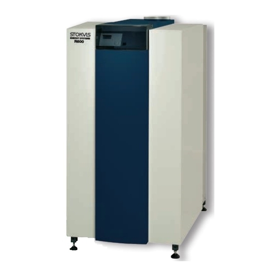
Stokvis R600 LMS Boiler
Gas-Fired
Floor Standing
Condensing
Installation, Operation & Maintenance
Manual
STOKVIS ENERGY SYSTEMS
96R Walton Road
East Molesey
Surrey
KT8 0DL
Tel: 020 8783 3050 / 0870 7707747
Fax: 020 8783 3051 / 0870 7707767
E-Mail:
info@stokvisboilers.com
Website:
www.stokvisboilers.com
420010567300 12/2013
Advertisement
Table of Contents

Related Manuals for STOKVIS ENERGY SYSTEMS R601


Summary of Contents for STOKVIS ENERGY SYSTEMS R601
- Page 1 Stokvis R600 LMS Boiler Gas-Fired Floor Standing Condensing Installation, Operation & Maintenance Manual STOKVIS ENERGY SYSTEMS 96R Walton Road East Molesey Surrey KT8 0DL Tel: 020 8783 3050 / 0870 7707747 Fax: 020 8783 3051 / 0870 7707767 E-Mail: info@stokvisboilers.com Website: www.stokvisboilers.com...
-
Page 3: Table Of Contents
Contents Contents ..............Safety General regulations ........Application ..........Norms and regulations ......Construction Layout of boiler .......... Operating principle ........Technical data ..............Extent of delivery Standard boiler .......... Accessories ..........Installation Boiler transport .......... Removing the casing ......... Boiler installation ........ -
Page 4: Safety
Safety General regulations Application Norms and regulations General regulations The R600 boiler is CE approved and EN 61000-3-2 (2000) This documentation contains important applies to the following European Electromagnetic compatibility (EMC) - information, which is a base for safe standards: Part 3-2: Limits - Limits for harmonic ... -
Page 5: Construction
Construction Layout of boiler Operating principle Layout of boiler The R600 boiler consists of the follow- ing main components: Casing Front panel Adjustable feet Control panel (below cover) Flue gas connection Air intake connection (under casing) Gas connection Flow water connection Return water connection 10 2nd (hot) return water connection (for split system use), accessory... -
Page 6: Technical Data
Technical data R601 R602 R603 R604 R605 R606 R607 Nominal heat output at 80/60ºC max/min* 142.1/24.0 190.1/40.6 237.2/40.6 285.2/40.6 384.5/79.6 480.6/79.6 545.1/79.6 Nominal heat output at 75/60ºC max/min* 142.2/24.0 190.3/40.6 237.4/40.6 285.5/40.6 384.9/79.7 481.1/79.7 545.6/79.7 Nominal heat output at 40/30ºC max/min* 150.4/25.5 201.2/43.1 251.0/43.1 301.8/43.1 402.4/83.6 502.9/83.6 570.4/83.6... - Page 7 Technical data Dimension R601 R602 R603 R604 R605 R606 R607 Electrical connections Gas supply 1105 1260 1470 1220 1435 1585 1735 Water supply Water return (Cold) 127.5 127.5 137.5 137.5 187.5 187.5 187.5 Air Intake (under casing) 1480 1480 1500...
-
Page 8: Extent Of Delivery
complete system solution. Ask your Gas valve leakage tester (not possi- supplier for more detailed information. ble for R601); 2nd Return connection for Split System use; Controlled bypass (incl. pump) incl. -
Page 9: Installation
The R600 boiler will be supplied as a complete unit being fully assembled and pre-tested. The maximum width is 670mm for models R601-R603 and 770mm for models R604-R607, which makes it possible to transport all mo- dels through a normal door in one pie- ce. -
Page 10: Removing The Casing
Installation Removing the casing Boiler transport Remove the casing before transporting the boiler, in order to avoid damage to the casing parts during transportation. Removing the casing is done as fol- lows:... -
Page 11: Boiler Installation
Installation Boiler installation Boiler installation The boiler should be positioned in a frost-proof boiler room. If the boiler room is on the roof, the boiler itself may never be the highest point of the instal- lation. When positioning the boiler, please note the recommended minimum clea- rance in the picture. -
Page 12: Connecting The Boiler
Installation Connecting the boiler Connecting the boiler Hydraulic connections This chapter will explain how to make The boiler should always be connected all connections to the boiler with regard in such a way, that water flow through the boiler can be ensured at all times. ... - Page 13 Installation Connecting the boiler Gas connection (1) It’s recommended to use stainless The gas connection must be made by steel or PPS fluegas systems an authorized installer in accordance The diameter of the flue gas system with the applicable national and local must be chosen by calculation ac- standards and regulations.
-
Page 14: Wiring Diagram - Boiler
Installation Wiring diagram - Boiler Heating circuit 2 Heating circuit 1 Return Flow temp. sensor temp. sensor... - Page 15 Installation Wiring diagram - Boiler Flue gas temp. sensor Lockout input...
-
Page 16: Wiring Diagram - Accessories
Installation Wiring diagram - Accessories Flow temp. sensor Mixing valve control (0.5A max.) Heating circuit pump (2A max.) Flow temp. sensor Mixing valve control (0.5A max.) Heating circuit pump (2A max.) - Page 17 Installation Wiring diagram - Accessories * Remove jumper when connecting device Max. water Max. water Max. gas Boiler temp. pressure switch pressure switch pressure switch Leakage test Gas valve...
-
Page 18: Commissioning
Commissioning Water and hydraulic system Commissioning of the boiler should be This chapter explains the commissio- carried out by authorized personnel ning of the boiler with the standard boi- only. Failure to respect this condition ler controller. When an additional sys- makes the guarantee void. -
Page 19: Gas Supply
Commissioning Gas supply Condensate connection Flue and air intake connections Gas supply Check the gas supply connection to the boiler for tightness. If any leakage is found, reseal the leakage before star- ting the boiler! Remove any air between the gas valve and the gas line. -
Page 20: Prepare Boiler For First Startup
Commissioning Prepare boiler for first startup Preparation for first startup Legend: On/off switch Open the gas supply; Return (ESC) Enable the power supply to the boiler; Room temperature control Confirmation (OK) Switch on the boiler with the on/off Manual mode switch (A);... - Page 21 Combustion check at full load for natural gas G20 / G25 Start the boiler in controller stop mode and go to 50% load. Now the boiler R601-R607 operates at 50% load. Allow the boiler 10.2 ± 0.2 2, max to stabilise the combustion for 3 minutes.
-
Page 22: Check Water Flow
(see table below for nominal data): = √(∆p / ∆p ) * q actual measured nominal nominal Water flow data R601 R602 R603 R604 R605 R606 R607 Nominal flow rate 10.2 12.2 16.3 20.4... -
Page 23: Check Functionality Of Safety Devices
Commissioning Check functionality of safety devices Gas tightness check Boiler shut down Check functionality of safety devices Ionisation electrode (6) All safety devices have to be checked Remove electrical connection from the on good functioning. Safety devices on ionisation electrode while the boiler is a standard boiler are a water flow tem- running, the boiler will go in lockout no. -
Page 24: Commissioning Protocol
Commissioning Commissioning protocol Commissioning Protocol R600 Project Boiler type Project Serial number Address Year City Nominal load (Hi) [kW] Date Nominal output (Hi) [kW] Engineer System Water pressure [bar] Installati- Roof top Water pH Ground floor Water hardness [dºH] Basement ... -
Page 25: Operating Instructions
Operating instructions Controls Legend: On/off switch Return (ESC) Room temperature control Confirmation (OK) Manual mode Chimney sweeper mode Info mode Reset button Operation mode heating zone(s) Display Operation mode DHW Operation mode DHW (M) Deaeration mode (E) Confirmation (OK) (D) For switching on the DHW operation By pressing the manual mode button Return (ESC) (B) -
Page 26: Display / Programming
Operating instructions Display / Programming DHW mode selection Heating operation mode selection (Controller Stopp mode when pressing > 3 sec.) Display Info button Confirm Quit menu Manual mode (Deaeration mode when pressing Reset > 3 sec.) Chimney sweeper mode Select (turn left/right) Heating to comfort setpoint Info level activated Heating to reduced setpoint Programming activated... -
Page 27: Overview Of Main Functions
Operating instructions = confirmation = cancel, return to main Overview of main functions menu Button Action Procedure Display / Function Zone 1 and zone 2 Actuate wheel left/right Comfort setpoint with blinking temperature Set room temperature Turn wheel Blinking temperature in 0,5 °C steps from 10 to 30 °C Confirm with OK button or wait 5 sec. -
Page 28: Maintenance
Maintenance Checklist Replacing the electrodes Checklist Maintenance of the boiler should be carried out by authorized personnel The following activities must be carried only. out, see following paragraphs for an extensive description of the main activi- In order to ensure continued good and ties: safe operation of the boiler, it should be ... -
Page 29: Cleaning The Condensate Receptacle
Maintenance Cleaning the condensate receptacle Cleaning and refilling the syphon Inspection of combustion chamber Cleaning the condensate receptacle Disconnect the plug of the fluegas temperature sensor (1); Remove the internal fluegas pipe (2) of the boiler in order to create access to the condensate receptacle;... -
Page 30: Water Pressure And Quality
Maintenance Water pressure and quality Combustion analysis Gas tightness check Check if the water pressure and quality Check the combustion at full load and Check the tightness of all sealed con- meet the requirements. Consult the minumum load, correct the settings if nections with an approved soap or chapter “commissioning: water and necessary. -
Page 31: Maintenance Protocol
Maintenance Maintenance Protocol Maintenance Protocol R600 Project Boiler type Project Serial number Address Year City Nominal load (Hi) [kW] Date Nominal output (Hi) [kW] Engineer System Water pressure [bar] Water pH Water hardness [dºH] Water chloride [mg/l] Water ∆T full load [ºC] Water ∆p [kPa]... -
Page 32: Lockouts
Lockouts In case of a lockout, a warning symbol ( ) and a flashing error code appears on the display. The cause of a fault should first be determined and eliminated before the boiler is being reset. The table below shows all possible lockouts with indication of possible cause. - Page 33 Lockouts Error Description of error code Internal error Parameterization error Unit manually locked Fan error LP error, does not close Error heating circuit flow switch LP error, does not open Alarm contact H1 or H4 active Alarm contact H2 (EM1, EM2 or EM3) or H5 active Alarm contact H6 active Alarm contact H3 or H7 active Limit thermostat heating circuit 1...
- Page 34 Lockouts Error Description of error code Buffer return valve Y15 not available Puffer address sensor Primary controller / system pump address error Pressureless header address error Common flow sensor B10 not available Flow temperature 3 (heating circuit 3) supervision Limit thermostat heating circuit 3 Extension module 3 error (collective error) Buffer return valve Y15 not available Puffer address sensor...
-
Page 35: Sensor Values
Sensor values The diagrams show the sensor values NTC 10kΩ temperature sensor for all boiler sensors and optional sen- (flow, return, flue gas, DHW and header sensor) sors available in accessory kits. The diagrams contain average values, as all sensors are liable to tolerances. 60000 When measuring the resistance values, 55000... -
Page 36: Declaration Of Conformity
Declaration of Conformity Declaration of Conformity Rendamax BV, Hamstraat 76, 6465 AG Kerkrade (NL), Declares that the product R600 Is in conformity with the following standards: EN 298 EN 656 EN 15420 EN 55014-1 / -2 EN 61000-3-2 /-3 EN 60 335-1/ -2 And in accordance with the guidelines of directives: 92 / 42 / EEC (boiler efficiency directive) 2009 / 142 / EEC (gas appliance directive) - Page 38 STOKVIS ENERGY SYSTEMS 96R Walton Road East Molesey Surrey KT8 0DL Tel: 020 8783 3050 / 0870 7707747 Fax: 020 8783 3051 / 0870 7707767 E-Mail: info@stokvisboilers.com Website: www.stokvisboilers.com 420010567300 12/2013...
Need help?
Do you have a question about the R601 and is the answer not in the manual?
Questions and answers