STOKVIS ENERGY SYSTEMS R600 Options & Systems Planner Manual
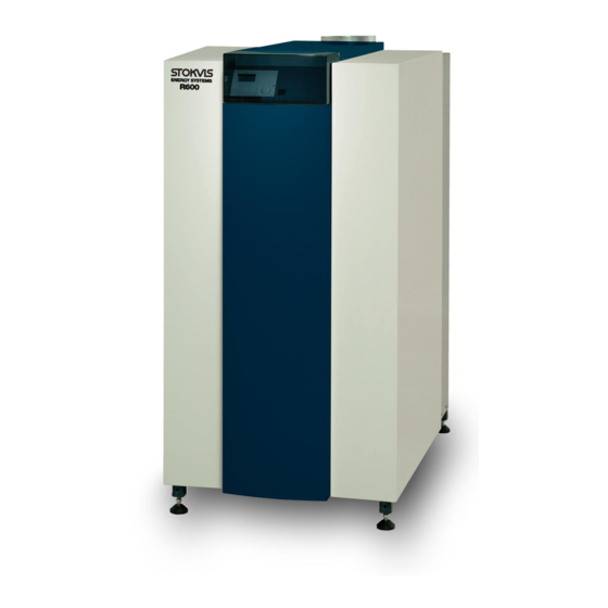
Lms boiler
gas-fired
floor standing condensing
Hide thumbs
Also See for R600:
- Installation, operation & maintanance manual (44 pages) ,
- Installation, operation & maintenance manual (46 pages)
Table of Contents
Advertisement
Quick Links
Stokvis R600 LMS Boiler
Gas-Fired
Floor Standing
Condensing
Options & Systems
Planner Manual
STOKVIS ENERGY SYSTEMS
96R Walton Road
East Molesey
Surrey
KT8 0DL
Tel: 020 8783 3050 / 0870 7707747
Fax: 020 8783 3051 / 0870 7707767
E-Mail:
info@stokvisboilers.com
Website:
www.stokvisboilers.com
DOC2075 Art.Nr. 12 100 459 07/2010
Advertisement
Table of Contents

Related Manuals for STOKVIS ENERGY SYSTEMS R600


Summary of Contents for STOKVIS ENERGY SYSTEMS R600
- Page 1 Stokvis R600 LMS Boiler Gas-Fired Floor Standing Condensing Options & Systems Planner Manual STOKVIS ENERGY SYSTEMS 96R Walton Road East Molesey Surrey KT8 0DL Tel: 020 8783 3050 / 0870 7707747 Fax: 020 8783 3051 / 0870 7707767 E-Mail: info@stokvisboilers.com Website: www.stokvisboilers.com...
-
Page 2: Table Of Contents
Contents Gas condensing boiler R600 Models and output ....................4 Application possibilities..................4 Value propositions ....................4 Technical description Description ......................4 Technical data ....................... 5 Dimensions ......................6 Declaration of conformity ..................7 Extent of delivery ....................8 Boiler transport ...................... 8 Boiler installation .................... - Page 3 Contents Accessories System selection ....................21 Plug & Play kits Kit A: 2x max. Water pressure switch + 1x external high limit thermostat ... 22 Kit B: max. gas pressure switch ................22 Kit C: external high limit thermostat ..............22 Kit D: gas valve leakage tester ................
-
Page 4: Gas Condensing Boiler R600 Models And Output
The floor standing gas condensing boi- The gas condensing boiler R600 is Unique reliability ler R600 is available in 7 types within applicable for alle central heating sys- proven technology with exceptional an output range from 142 until 539 kW. -
Page 5: Technical Data
Technical discription Technical data R601 R602 R603 R604 R605 R606 R607 Nominal heat output at 80-60ºC max/min* 142.1/23.3 190.1/39.5 237.2/39.5 285.2/39.5 380.2/76.6 475.3/76.6 539.0/76.6 Nominal heat output at 75-60ºC max/min* 142.2/23.5 190.3/39.5 237.4/39.5 285.5/39.5 380.6/76.6 475.8/76.6 539.6/76.6 Nominal heat output at 40/30ºC max/min* 150.7/26.7 201.6/45.2 251.4/45.1 302.3/45.2 403.1/87.7 503.9/87.7 571.5/87.7 Nominal heat input Hi max/min* 145.0/24.5 194.0/41.5 242.0/41.5 291.0/41.5 388.0/80.5 485.0/80.5 550.0/80.5... -
Page 6: Dimensions
Technical description Dimensions Dimensions R601 R602 R603 R604 R605 R606 R607 Electrical connections Gas supply 1105 1260 1470 1220 1435 1585 1735 Water supply Water return (Cold) 127.5 127.5 137.5 137.5 187.5 187.5 187.5 Air Intake (under casing) 1480 1480 1500 1500 1500... -
Page 7: Declaration Of Conformity
Technical description Declaration of conformity Declaration of Conformity Rendamax BV, Hamstraat 76, 6465 AG Kerkrade (NL), Declares that the product R600 Is in conformity with the following standards: EN 298 EN 656 EN 15420 EN 55014-1 / -2 EN 61000-3-2 /-3... -
Page 8: Extent Of Delivery
Technical description Extent of delivery Boiler transport Boiler installation Standard boiler A boiler delivery package contains the following components: Component Pcs. Package Boiler fully assembled and tested Mounted on wooden blocks with wooden border, sealed in PE foil Adjustable feet Mounted on frame of the boiler Syphon for condensate connection Cardboard box on top of heatexchanger... -
Page 9: Norms And Regulations Regulations
Norms and regulations The R600 boiler is CE approved and Norms and regulations EN 61000-3-2 applies to the following European When installing and operating the Electromagnetic compatibility (EMC) - standards: boiler, all applicable norms (european Part 3-2: Limits - Limits for harmonic ... -
Page 10: Maintenance
H, L and be used in both non-roomsealed and on of the installation. For the R600, one LL, and for LPG. Factory settings are roomsealed applications. The com- annual maintenance visit is recommen- always done for H-gas. -
Page 11: Noise Protection
Antifreeze The R600 can be used with the an- tifreeze type Shell Antifreeze Con- centrate. The concentration of the an- tifreeze in the system affects the maxi- mum capacity the boiler can work on. -
Page 12: Flue Gas System Requirements And Regulations
The R600 is certified for the flue gas systems B23 (and B23P for France) and C33, C53 and C63. Flue gas data... -
Page 13: Dimensioning
Flue gas system Dimensioning Dimensioning VERSION 1 Calculation base: When dimensioning a flue gas system, Total connection length in boiler room ≤ 1.5 m; it’s necessary to perform a calculation check of the flue gas system in order to 2x 87°-bend verify if the choosen system is appli- Maximum permissible height (h) of flue gas cable. -
Page 14: Neutralisation General
Standard neutralisation system (DN) Neutralisation system with pump (HN) General The maximum amount of condensate Condensate, created by the R600, for each boiler type can be found in the should be drained into the public drai- chapter „Technical data“. ning system. The condensate PH is between 3.0 and 3.5. -
Page 15: Hydraulic Connection Hydraulic Resistance
In the graph the resistance for a specific flow rate can be found. The R600 is able to control a speed controlled pump via a 0-10VDC signal. It makes the flow rate modulate in pa- rallel with the burner load. -
Page 16: Hydraulic Connection Into A System
Hydraulic connection into a system Details to the 3 possibilities mentioned Standard, with low loss header or The R600 must be connected in such a above, can be found in the next secti- plate heat exchanger way, that a minimum flow rate of 30% ons. -
Page 17: Split System
Hydraulic connection Split System Split System The split system boiler enables the connection of two returns with different water temperatures. By evasing the low loss header the cold return water enters the condensor of the boiler directly, without mixing with the high temepra- ture return water (f.e. -
Page 18: Controls Basic Controls And Connections
Control by building managemant Boiler enable signal, terminals 111- system 112 (volt free) The R600 can be connected to a buil- The boiler enable signal is provided ding management system. This can be with a jumper from the factory. When... -
Page 19: Capacity Feedback Signal
Controls Capacity feedback signal OK/Alarm output signal Capacity feedback signal, terminals 130-131 (0-10VDC) This signal is available at the mentio- ned terminals, when the burner is acti- ve. The following graph shows the va- lue of the signal. OK/Alarm output signal, terminals 3-4-5 (230VAC) or extension module AVS75 (contact QX21) when combi- ned with external gas valve and/or... -
Page 20: Heating Zone Control
Cascade control Heating zone control Cascade control The R600 can be extended with an The R600 can be controlled in a casca- AVS75 controller for extended heating de system of maximum 8 boilers. This zone control. The AVS75 enables can be done by using the integrated... -
Page 21: Accessories System Selection
Accessories System selection Selection table The R600 is supplied from the factory with LMS14 boiler management unit. Additional a wide variation of accessory kits is available. The accessory kits are specially designed for the R600 and are very easy to combine with the boiler to create a complete system solution. -
Page 22: Plug & Play Kits
Accessories Plug & play kits Kit A: 2x max. Water pressure switch The connection piece is pre-assembled + 1x external high limit thermostat with the following components: The kit includes a connection piece, 2x maximum water pressure switch which can be connected the flow con- ... -
Page 23: Kit G: Plate Heat Exchanger + Connection Kit
Accessories Plug & play kits Data secundary circuit plate heat Kit G: plate heat exchanger + con- exchanger nection kit ΔT=10K ΔT=15K ΔT=20K The kit contains a plate heat ex- changer including connection mate- /h] [kPa] [m /h] [kPa] [m /h] [kPa] rial, automatic de-aerator and expan- R601 12.2... -
Page 24: Kit I: Qaa75
Accessories Plug & play kits Kit I: QAA75 Kit K: extension AVS75 Kit L: pump 3-step The kit contains a QAA75 room unit, The kit contains an AVS75 extension The kit includes a 3-step pump includ- which communicates with the boiler via module incl. - Page 25 Accessories Plug & play kits UPS32-60F UPS32-120F UPS50-120F UPS65-120F...
-
Page 26: Kit M: Speed Controlled Pump
Accessories Plug & play kits Kit M: speed controlled pump The pump is electrically wired, and can The kit includes a speed controlled be connected directly to the terminals in pump including connection material the boiler. Consult the wiring diagram with connection possibility for an ex- for more details. -
Page 27: Kit N/O/P/Q: Safety Valve (3-4-5-6 Bar) Tüv + Manometer + De-Aerator
Accessories Plug & play kits MAGNA40-100F MAGNA50-120F Kit N/O/P/Q: safety valve (3-4-5-6 The connection piece has an additional bar) TÜV + manometer + de-aerator connection for kit A, in order to combine The kit includes a connection piece, both kits on one piece. which can be connected the flow con- nection of the boiler. -
Page 28: Connection Possibilities
Connection possibilities Low loss header Boiler type Boiler type Boiler type R601-R603 1233 R601-R603 R601-R603 R604-R605 1299 R604-R605 1096 R604-R605 1119 R606-R607 1299 R606-R607 1096 R606-R607 1119 Boiler type Boiler type Boiler type R601-R603 1191 R601-R603 R601-R603 R604-R605 1320 R604-R605 1119 R604-R605 1138... -
Page 29: Plate Heat Exchanger
Connection possibilities Plate heat exchanger Boiler type Boiler type Boiler type R601-R603 1421 R601-R603 R601-R603 1047 R604-R605 1667 R604-R605 1133 R604-R605 1222 R606-R607 1542 R606-R607 1073 R606-R607 1278 Boiler type Boiler type Boiler type R601-R603 1379 R601-R603 R601-R603 1005 R604-R605 1156 R604-R605 1243... -
Page 30: Installation Examples 2-A-C: 1 Heating Zone + Low Loss Header
Installation examples 2-A-C: 1 heating zone + low loss header 2-A-C: 1 heating zone + low loss header Description R600 with low loss header Weather compensated control 1 mixed heating zone Tips Complete accessory kits with low loss header are available for ∆T=10-20K... -
Page 31: 2-5-A-C: 1 Heating Zone And Sanitary Hot Water + Low Loss Header
2-5-A-C: 1 heating zone and sanitary hot water + low loss header 2-5-A-C: 1 heating zone and sanitary hot water + low loss header Description R600 with low loss header Weather compensated control 1 mixed heating zone ... -
Page 32: 4-A-C: 2 Heating Zones + Low Loss Header
Installation examples 4-A-C: 2 heating zones + low loss header 4-A-C: 2 heating zones + low loss header Description R600 with low loss header Weather compensated control 2 mixed heating zones Tips Complete accessory kits with low loss header are available for ∆T=10-20K... -
Page 33: 4-5-A-C: 2 Heating Zones And Sanitary Hot Water + Low Loss Header
4-5-A-C: 2 heating zones and sanitary hot water + low loss header 4-5-A-C: 2 heating zones and sanitary hot water + low loss header Description R600 with low loss header Weather compensated control 2 mixed heating zones ... -
Page 34: A-C: Boiler Control Via 0-10Vdc + Low Loss Header
Installation examples A-C: Boiler control via 0-10VDC + low loss header A-C: Boiler control via 0-10VDC + low loss header Description R600 with low loss header Tips Complete accessory kits with low loss header are available for ∆T=10-20K (see chapter „Accessories“). -
Page 35: 2-B-C: 1 Heating Zone + Plate Heat Exchanger
Installation examples 2-B-C: 1 heating zone + plate heat exchanger 2-B-C: 1 heating zone + plate heat exchanger Description R600 with plate heat exchanger Weather compensated control 1 mixed heating zone Tips Complete accessory kits with plate heat exchanger are available for ∆T=10-20K (see chapter... -
Page 36: 2-5-B-C: 2 Heating Zones And Sanitary Hot Water + Plate Heat Exchanger
2-5-B-C: 2 heating zones and sanitary hot water + plate heat exchanger 2-5-B-C: 2 heating zones and sanitary hot water + plate heat exchanger Description R600 with plate heat exchanger Weather compensated control 1 mixed heating zone ... -
Page 37: 4-B-C: 2 Heating Zones + Plate Heat Exchanger
Installation examples 4-B-C: 2 heating zones + plate heat exchanger 4-B-C: 2 heating zones + plate heat exchanger Description R600 with plate heat exchanger Weather compensated control 2 mixed heating zones Tips Complete accessory kits with plate heat exchanger are available for ∆T=10-20K (see chapter... -
Page 38: 4-5-B-C: 2 Heating Zones And Sanitary Hot Water + Plate Heat Exchanger
4-5-B-C: 2 heating zones and sanitary hot water + plate heat exchanger 4-5-B-C: 2 heating zones and sanitary hot water + plate heat exchanger Description R600 with plate heat exchanger Weather compensated control 2 mixed heating zones ... -
Page 39: B-C: Boiler Control Via 0-10Vdc + Plate Heat Exchanger
Installation examples B-C: Boiler control via 0-10VDC + plate heat exchanger B-C: Boiler control via 0-10VDC + plate heat exchanger Description R600 with plate heat exchanger Tips Complete accessory kits with plate heat exchanger are available for ∆T=10-20K (see chapter „Accessories“). -
Page 40: 4-5-A-C-E: 2 Heating Zones And Sanitary Hot Water + Cascade Via Low Loss Header
4-5-A-C-E: 2 heating zones and sanitary hot water + cascade via low loss header 4-5-A-C-E: 2 heating zones and sanitary hot water + cascade via low loss header Description 2x R600 with low loss header Cascade control + weather compen- sation ... -
Page 41: Extension 2 Heating Zones
Installation examples Extension 2 heating zones Extension 2 heating zones Description Weather compensated controller with wall hung box LOGON B Extension of 2 heating zones Tips The extension controller should al- ways be used in combination with the integrated boiler controller LMS14 ... -
Page 42: Norms
G4 Heizraumrichtlinie Technische Regeln für Gas- Risparmio energetico Installationen DVGW-TRGI 86/96 Legge 9 gennaio 1991 n.10 Der R600 ist zugelassen nach Artikel VDI2035 15a B-VG und gemäß Feuerungsanla- D.P.R. 26-08-93 n.412 genverordnung VO (FAV 97) D.P.R. n.551 del 21 dicembre 1999 Netherlands: Die örtlichen Bauordnungen sind zu... - Page 44 STOKVIS ENERGY SYSTEMS 96R Walton Road East Molesey Surrey KT8 0DL Tel: 020 8783 3050 / 0870 7707747 Fax: 020 8783 3051 / 0870 7707767 E-Mail: info@stokvisboilers.com Website: www.stokvisboilers.com DOC2075 Art.Nr. 12 100 459 07/2010...
Need help?
Do you have a question about the R600 and is the answer not in the manual?
Questions and answers