Table of Contents
Advertisement
Quick Links
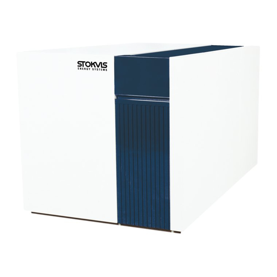
Stokvis R3400/R3600 Boiler
Gas-Fired
Floor Standing
Condensing
Installation, Operation & Maintenance
Manual
STOKVIS ENERGY SYSTEMS
96R Walton Road
East Molesey
Surrey
KT8 0DL
Tel: 020 8783 3050 / 0870 7707747
Fax: 020 8783 3051 / 0870 7707767
E-Mail:
info@stokvisboilers.com
Website:
www.stokvisboilers.com
420010567700 12/2013
Advertisement
Table of Contents

Related Manuals for STOKVIS ENERGY SYSTEMS R3600


Summary of Contents for STOKVIS ENERGY SYSTEMS R3600
- Page 1 Stokvis R3400/R3600 Boiler Gas-Fired Floor Standing Condensing Installation, Operation & Maintenance Manual STOKVIS ENERGY SYSTEMS 96R Walton Road East Molesey Surrey KT8 0DL Tel: 020 8783 3050 / 0870 7707747 Fax: 020 8783 3051 / 0870 7707767 E-Mail: info@stokvisboilers.com Website: www.stokvisboilers.com...
-
Page 2: Table Of Contents
Contents Contents ........................2 Safety General regulation .................... 3 Application ......................3 Norms and regulations ..................3 Construction Layout of boiler ....................4 Operating principle ................... 4 Technical data ......................... 5 Extent of delivery Standard boiler ....................13 Accessories ....................13 Installation Transport ...................... -
Page 3: Safety General Regulation
Safety General regulations Application Norms and regulations General regulations The R3400/R3600 boiler is CE ap- EN 61000-3-2 proved and applies to the following This documentation contains important Electromagnetic compatibility (EMC) - information, which is a base for safe European standards:... -
Page 4: Construction Layout Of Boiler
Construction Layout of boiler Operating principle Layout of boiler The R3400/R3600 boiler consists of the following main components: Return water connection Flue gas connection Water flow switch Safety valve Flow water connection Filling/draining valve Top plate Plenum Burner 10 1st Heat exchanger... -
Page 5: Technical Data
Technical data Technical data R3401 - R3405 R3401 R3402 R3403 R3404 R3405 Nominal heat output at 80-60ºC max/min 656/164 733/183 857/213 971/242 1084/270 Nominal heat output at 75-60ºC max/min 657/164 734/183 858/213 972/242 1085/270 Nominal heat output at 40/30ºC max/min 663/181 741/202 867/236... - Page 6 Technical data Technical data R3406 R3406 Nominal heat output at 80-60ºC max/min 1196/298 Nominal heat output at 75-60ºC max/min 1197/298 Nominal heat output at 40/30ºC max/min 1209/329 Nominal heat input Hi max/min* 1279/320 Efficiency at 80/60ºC 93.5 Efficiency at 40/30ºC 94.5 Annual efficiency (NNG 75/60ºC) 100.0...
- Page 7 Technical data Dimensions R3401 - R3406 Dimensions R3401 R3402 R3403 R3404 R3405 R3406 2265 2265 2653 2653 2658 2658 1166 1166 1166 1166 1355 1355 1355 1355 1355 1355 1125 1125 1570 1420 1155 1377 1330 1330 1130 1130 1330 1330 1160 1210...
- Page 9 Technical data Technical data R3600 - R3605 Standard R3600 R3601 R3602 R3603 R3604 R3605 Nominal heat output at 80-60ºC max/min 572/142 639/182 747/212 846/241 945/269 1043/297 Nominal heat output at 75-60ºC max/min 576/144 643/184 753/215 852/243 952/272 1050/300 Nominal heat output at 40/30ºC max/min...
- Page 10 Technical data Dimensions R3600 - R3605 Standard Dimensions R3600 R3601 R3602 R3603 R3604 R3605 1958 2265 2653 2653 2658 2658 1166 1166 1166 1166 1355 1405 1405 1405 1405 1405 1175 1450 1450 1205 1427 1230 1330 1130 1130 1330...
-
Page 13: Extent Of Delivery Standard Boiler
A boiler delivery package contains the following components: Component Pcs. Package R3400/R3600 Boiler fully assembled and tested Mounted on wooden blocks with wooden border, sealed in PE foil Adjustable feet Cardboard box on top of boiler Syphon for condensate connection... -
Page 14: Installation Transport
The table below shows the main dismantled parts with their weight and dimensions. When the R3400/R3600 boiler has to be transported with a crane, it is neces- sary to remove the casing before con- necting the boiler to the crane. Always connect the crane to the frame of the boiler by using straps. -
Page 16: Removing The Casing
Installation Removing the casing Boiler transport Remove the casing before transporting the boiler, in order to avoid damage to the casing parts during transportation. Removing the casing is done as fol- lows:... -
Page 17: Boiler Installation
Installation Boiler installation Boiler installation The boiler should be positioned in a frost-proof boiler room. If the boiler room is on the roof, the boiler itself may never be the highest point of the instal- lation. When positioning the boiler, please 1000 note the recommended minimum clea- rance in the picture. -
Page 18: Connecting The Boiler
If the boiler is used in a system with two return cir- cuits (only R3600 series), the common return becomes the low temperature return, the 2nd return connection is the high temperature return (remove cap/ flange before connecting). - Page 19 Installation Connecting the boiler Gas connection (6) It’s recommended to use stainless The gas connection must be made by steel systems an authorized installer in accordance The diameter of the flue gas system with the applicable national and local must be chosen by calculation ac- standards and regulations.
-
Page 20: Commissioning Water And Hydraulic System
VDI2035 standard. In the table you can find the nominal va- lues for filling and additional water for the R3400/R3600 according to the the VDI2035. The table at the left gives an indication Concentrate... -
Page 21: Gas Supply
Commissioning Gas supply Condensate connection Flue and air intake connections Gas supply Check the gas supply connection to the boiler for tightness. If any leakage is found, reseal the leakage before star- ting the boiler! Remove any air between the gas valve and the gas line. -
Page 22: Prepare Boiler For First Startup
Commissioning Prepare boiler for first startup Prepare boiler for first startup Open gas connection; Switch on mains isolator switch for power supply to the boiler; Switch on boiler with on/off switch (1) Make sure the boiler remains in standby operation use rotational switch (3);... -
Page 23: Combustion Analysis
Commissioning Combustion analysis Pilot burner Combustion check at full load Combustion settings Start the boiler at service mode for full for natural gas G20 / G25 load operation ( ). When you have All boilers reduced P9 to 50% (see previous chapter), the boiler will operate at 50% 10.0 ±... -
Page 24: Air Pressure Switch
Commissioning Air pressure switch Adjustment Air pressure switch Connect a pressure gauge to the indi- cated measuring points on the switch (1). Start the boiler at service mode for minimum load operation (W1). Measure the pressure differential across the switch, this should be ≈ 0.8 mbar. Turn the dial on the switch (2) counter- clockwise until the end. -
Page 25: Check Water Flow
41.8 46.8 ∆p at nom. flow [kPa] Flow rate R3406 at ∆T 20K R3406 Nominal flow 51,6 ∆p at nom. flow [kPa] Flow rate R3600 - R3605 at ∆T 20K R3600 R3601 R3602 R3603 R3604 R3605 Nominal flow 24,7 27,6... -
Page 26: Check Functionality Of Safety Devices
Commissioning Check functionality of safety devices Gas tightness check Boiler shut down Check functionality of safety devices Ionisation electrode (6) All safety devices have to be checked Remove electrical connection from the on good functioning. Safety devices on ionisation electrode while the boiler is a standard boiler are a water flow tem- running, the boiler will go in lockout perature sensor, water flow switch,... -
Page 27: Commissioning Protocol
Commissioning Commissioning protocol Commissioning Protocol R3400/R3600 Project Boiler type Project Serial number Address Year City Nominal load (Hi) [kW] Date Nominal output (Hi) [kW] Engineer System Water pressure [bar] Installati- Roof top Water pH Ground floor Water hardness [dºH]... -
Page 28: Operating Instructions Main Menu (Operating Mode)
Operating instructions Main menu (operating mode) Parameter menu (information/programming mode) Changing parameter values The boiler controller has two menus: the main menu (operating mode) when the lid is closed, and the parameter menu (information/programming mode) when the lid is open. Both menus and possibilities are explained in the next paragraphs. Main menu (operating mode) lid closed With the lid closed and by using the rotational switch (1) clockwise or anticlockwise the boilers’... -
Page 29: Maintenance Checklist
Maintenance Checklist Replacing the electrodes Maintenance of the boiler should be Checklist carried out by authorized personnel The following activities must be carried only. out, see following paragraphs for an extensive description of the main activi- In order to ensure continued good and ties: safe operation of the boiler, it should be inspected at least once per year. -
Page 30: Cleaning The Condensate Receptacle
Maintenance Cleaning the condensate receptacle Cleaning and refilling the syphon Cleaning the condensate receptacle Remove the inspection hatch (2) to access the inside of the condensate receptacle; Clean the receptacle; Mount the inspection hatch. Water pressure and quality Check if the water pressure and quality meet the requirements. -
Page 31: Safety Devices
Maintenance Maintenance Protocol Maintenance Protocol R3400/R3600 Project Boiler type Project Serial number Address Year City Nominal load (Hi) [kW] Date Nominal output (Hi) [kW] Engineer System Water pressure [bar] Water pH Water hardness [dºH] Water chloride [mg/l] Water ∆T full load [ºC]... -
Page 32: Lockouts
Lockouts In case of a lockout, a warning triangle (E) and a flashing error code appears on the display. The cause of a fault should first be determined and eliminated before the boiler is being reset. In case the lockout appears more than twice within 6 minutes or maintains for longer than 6 minutes, the error code is added with a “... - Page 33 Lockouts No. Error type Explanation Possible solution Lockout Error gas valve V1, flame ionisation signal detec- Check closing position of valve V1 within gas combi ted longer than 5 seconds after burner stop. valve, replace gas valve. Lockout Error gas valve V2, flame ionisation signal detec- Check closing position of valve V2 within gas combi ted longer than 5 seconds after burner stop.
-
Page 34: Sensor Values
Sensor values The diagrams show the sensor values Water flow and fluegas temperature sensor (5kΩ NTC) for all boiler sensors and optional sen- sors available in accessory kits. The diagrams contain average values, as all sensors are liable to tolerances. When measuring the resistance values, the boiler should always be switched off. -
Page 35: Declaration Of Conformity
Declaration of Conformity Declaration of Conformity Rendamax BV, Hamstraat 76, 6465 AG Kerkrade (NL), declares that the products R3400/R3600 are in conformity with the following standards: EN 656 EN 15417 EN 13836 EN 55014-1 / -2 EN 61000-3-2 /-3 EN 60 335-1/ -2... - Page 38 STOKVIS ENERGY SYSTEMS 96R Walton Road East Molesey Surrey KT8 0DL Tel: 020 8783 3050 / 0870 7707747 Fax: 020 8783 3051 / 0870 7707767 E-Mail: info@stokvisboilers.com Website: www.stokvisboilers.com 420010567700 12/2013...
Need help?
Do you have a question about the R3600 and is the answer not in the manual?
Questions and answers