
Related Manuals for Torque Fitness TQ5-001


Summary of Contents for Torque Fitness TQ5-001
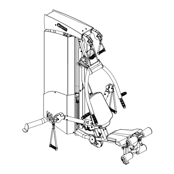
- Page 1 Hybrid Strength Technology Gym System Assembly and Maintenance Guide Version: TQ5-001 Part #: 5158001-A...
-
Page 2: Table Of Contents
TABLE OF CONTENTS Important Safety Instructions …………………………………………………..3 Important Safety Instructions for Using the Equipment ……………..3 Important Safety Instructions for Assembling the Equipment …………3 Obtaining Service………………………………………………....3 General Notes………………………………………………………………………4 Unpacking the Equipment………………………………………………….4 Tools Required………………………………………………………………4 Optional Equipment…………………………………………………………4 Assembly Tips……………………………………………………………….4 Parts List…………………………………………………………………………….5 Assembly Instructions……………………………………………………………6-39 Adjustments and Maintenance………………………………………………….34-39 Cable Adjustments………………………………………………………….34 Attachment Instructions…………………………......….. -
Page 3: Important Safety Instructions
Do not disassemble, remove any parts or components or otherwise attempt to repair this product. DO NOT use product if product appears damaged. DO NOT attempt to fix a broken or jammed machine, obtain assistance from your authorized Torque Fitness Dealer. Failure to comply with these instructions will void any and all product warranties. -
Page 4: General Notes
Failure to do so may result the unit from or call Torque Fitness Customer Service. in clearance issues and will degrade the A 6-inch scale is provided at the bottom of aesthetics of your unit. - Page 5 Parts List PART NO. DESCRIPTION PART NO. DESCRIPTION 5139601 REAR BASE 5145301 BOTTOM RIGHT SHROUD 51237PA BASE 51454PA BOTTOM LEFT SHROUD 2001101 3/8” FLAT WASHER 5199401 3/4” SPACER 2004001 3/8 X 3/4” BUTTON HEAD BOLT W/NP 2002001 1/4” LOCK NUT 2004007 3/8 X 2-1/4”...
-
Page 6: Assembly
STEP 1 NOTE: Do NOT fully tighten. Assemble the BASE (2) to the REAR BASE (1) using: Two 3/8 X 3/4” BOLTS W/NP (4) Two 3/8” FLAT WASHERS (3) NOTE: Do NOT fully tighten any connec- tions until instructed to do so SECURELY. 3/8 X 3/4”... - Page 7 STEP 2 Assemble the REAR UPRIGHT (6) to the REAR BASE (1) using: Two 3/8 X 3/4” BOLTS (4) W/NP Two 3/8” FLAT WASHERS (3) NOTE: Do NOT fully tighten any connec- tions until instructed to do so SECURELY. 3/8 X 3/4” 4 W/NP Page 7...
- Page 8 STEP 3 Assemble the FRONT UPRIGHT (7) to the BASE (2) using: Two 3/8 X 2-3/4” BOLT (8) Four 3/8” FLAT WASHERS (3) Two 3/8” LOCK NUTS (15) NOTE: Do NOT fully tighten any connec- tions until instructed to do so SECURELY. 8 3/8 X 2-3/4”...
- Page 9 STEP 4 Assemble the MID PULLEY ARM PIVOT (16) to the FRONT UPRIGHT (7) & BASE (2) using: Four 3/8 X 2-3/4” BOLTS (8) Eight 3/8” FLAT WASHERS (3) Four 3/8” LOCK NUTS (15) NOTE: Do NOT fully tighten any connec- tions until instructed to do so SECURELY.
- Page 10 STEP 5 Assemble the TOP BOOM (17) to the FRONT UPRIGHT (7) using: 9 3/8 X 3” Two 3/8 X 3/4” BOLTS W/NP (4) Two 3/8” FLAT WASHERS (3) 4 3/8 X 3/4” Assemble the TOP BOOM (17) to the REAR W/NP UPRIGHT (6) using: Two 3/8 X 3”...
- Page 11 STEP 6 SECURELY TIGHTEN! SECURELY tighten ALL the previous frame connections. SECURELY TIGHTEN! SECURELY TIGHTEN! SECURELY TIGHTEN! Page 11...
- Page 12 STEP 7 SECURELY assemble the PRESS ARM PIVOT (68) to the FRONT UPRIGHT (7) using: 5 3/8 X 2-1/4” Two 3/8 X 2-1/4” BOLTS W/NP (5) W/NP Two 3/8” FLAT WASHERS (3) SECURELY assemble the PRESS ARM ADJ PLATE (69) to the PRESS ARM PIVOT (68) using: 3/8 X 2-1/4”...
- Page 13 STEP 8 Pull back SPRING PIN on the BASE (2) and slide the SEAT SUPPORT up to the top posi- tion. Make sure SPRING PIN engages the hole on the SEAT SUPPORT fully. SECURELY assemble the SEAT PAD (20) to the SEAT SUPPORT using: Two 3/8 X 2”...
- Page 14 STEP 9 To secure the SEAT PAD (20) to the BASE (2), tighten the KNOB on the vertical tube on the BASE (2). To adjust the SEAT PAD (20), loosen the KNOB on the BASE (2); pull out the POP PIN and pull up on the SEAT PAD (20).
- Page 15 STEP 10 SECURELY assemble the first PIVOT ARM (21) to the MID PULLEY ARM PIVOT (16) using: Two 3/8 X 2-1/4” BOLTS W/NP (5) Two 19mm PIVOT BUSHINGS (22) 3/8 X 2-1/4” 5 W/NP Page 15...
- Page 16 STEP 11 SECURELY assemble the remaining PIVOT ARM (21) to the MID PULLEY ARM PIVOT (16) using: Two 3/8 X 2-1/4” BOLTS W/NP (5) Two 19mm PIVOT BUSHINGS (22) 3/8 X 2-1/4” 5 W/NP Page 16...
- Page 17 STEP 12 SECURELY assemble the MID SWIVEL PUL- LEYS (23) to the PIVOT ARMS (21) using: Six 3/8 X 1/2” BOLTS (44) Six 3/8” CURVED WASHERS (11) 3/8 X 1/2” 44 W/NP Page 17...
- Page 18 STEP 13 SECURELY assemble the BACK PAD (24) to the back pad support bracket on FRONT UPRIGHT (7) using: Two 3/8 X 1-1/4” BOLTS (13) Two 3/8” FLAT WASHERS (3) (NOTE: Pull back on the BACK PAD SUP- PORT BRACKET POP PIN to rotate the BACK PAD SUPPORT BRACKET) 13 3/8 X 1-1/4”...
- Page 19 STEP 14 SECURELY assemble the LC KNEE HOLD DOWN (26) and the LE/LC ARM (25) to the FRONT UPRIGHT (7) using: Two 3/8 X 1-3/4” BOLTS W/NP (70) Two ORANGE PIVOT FLAT WASHERS (28) Two FLANGE SPACERS (27) 3/8 X 1-3/4” 70 SECURELY assemble the FLOATING TIBIA W/NP (32) to the LE/LC ARM (25) using:...
- Page 20 STEP 15 Insert two GUIDE RODS (29) into the bracket on the BASE (2) Apply GUIDE ROD LUBE (51) liberally over entire length of both GUIDE RODS (29). SELECTOR STOP Slide two WEIGHT STACK CUSHIONS (31) down over the GUIDE RODS (29). CAREFULLY slide nineteen WEIGHT PLATES (60) down over the GUIDE RODS (29) FLANGE...
- Page 21 STEP 16 4 3/8 X 3/4” W/NP SECURELY assemble the STACK/SHROUD SUPPORT (30) to the TOP BOOM (17) using: Two 3/8 X 3/4” W/NP BOLTS (4) Two 3/8” FLAT WASHERS (3) Slide the two 19mm SHAFT COLLARS (33) up against the STACK/SHROUD SUPPORT (30) and tighten the set screws on the 19mm SHAFT COLLARS (33) SECURELY.
- Page 22 STEP 17 Thread the JAM NUT end of the WEIGHT STACK CABLE (64) 3/4 of the way into the WEIGHT STACK HEAD PLATE (61) as shown. Make sure the cable runs in the groove of the pulleys. Page 22...
- Page 23 STEP 18 Route the ball end of WEIGHT STACK CABLE (64) thru the hole in the STACK SHROUD SUPPORT (30) and around the 6” PULLEY in the TOP BOOM (17) as shown. Loop the ball end of WEIGHT STACK CABLE (64) around the upper PULLEY in the DUAL FLOATING PULLEY (34) as shown.
- Page 24 STEP 19 Loop the ball end of WEIGHT STACK CABLE (64) around the upper 4-1/2” PULLEY on the FRONT UPRIGHT (7) and around the upper 3- 1/2” PULLEY in the PRESS ARM PIVOT (68) followed by the middle 4-1/2” PULLEY on the FRONT UPRIGHT (7) and around the lower 3- 1/2”...
- Page 25 STEP 20 Route the ball end of WEIGHT STACK CABLE (64) through the hole in the BASE (2) around the two 4-1/2” PULLEYS in the BASE (2) before looping the CABLE around the 3-1/2” SINGLE FLOATING PULLEY (36) as shown. Route the ball end of WEIGHT STACK CABLE (64) thru the hole in the plate on the BASE (2) and assemble one CABLE END SLEEVE (58)
- Page 26 STEP 21 Remove the bolt and 3-1/2” PULLEY from the 3-1/2” SINGLE FLOATING PULLEY (36) as shown. Route one end of the LEG CURL/LEG EXT CABLE (65) thru the bushing on the 3-1/2” SINGLE FLOATING PULLEY (36) and as- semble the CABLE END SLEEVE (58) as shown.
- Page 27 STEP 22 Thread one of the JAM NUTS on the end of the FLOATING PULLEY CABLE (66) 1/2 of the way into one of the 4-1/2” FLOATING PULLEY (35) as shown. Loop the other end of the FLOATING PULLEY CABLE (66) around the lower PULLEY in the 4-1/2”...
- Page 28 STEP 23 NOTE: The cable routing for each HIGH- MID PULLEY CABLE (67) is the same on both sides of the machine. Holding the cable end parallel with the floor and with the bolts facing up and down, carefully remove the bolts from the FAST ATTACH CABLE COUPLER on the HIGH-MID PULLEY CABLE (67) as shown.
- Page 29 STEP 24 Route the ball end of HIGH-MID PULLEY CABLE (67) around the 3-1/2” PULLEY in the BASE (2) as shown. Loop the ball end of the HIGH-MID PULLEY (67) around the pulley in the 4-1/2” FLOATING PULLEY (35). Route the ball end of HIGH-MID PULLEY CABLE (67) around the 4-1/2”...
- Page 30 STEP 25 Route the ball end of HIGH-MID PULLEY HOUSING CABLE (67) around the two PULLEYS in the BOLT COUPLER TOP BOOM (17) as shown. CORE SPRING Re-assemble the FAST ATTACH CABLE SLIDE ROLLER COUPLER to the ball end of the HIGH-MID PULLEY CABLE (67) using the following steps: Slide housing onto CABLE.
- Page 31 STEP 26 NOTE: The cable routing for each HIGH- MID PULLEY CABLE (67) is the same on HOUSING both sides of the machine. BOLT COUPLER CORE SPRING Holding the cable end parallel with the floor SLIDE and with the bolts facing up and down, carefully ROLLER remove the bolts from the FAST ATTACH CABLE COUPLER on the HIGH-MID PULLEY...
- Page 32 STEP 27 Route the ball end of HIGH-MID PULLEY CABLE (67) around the 3-1/2” PULLEY in the BASE (2) as shown. Loop the ball end of the HIGH-MID PULLEY (67) around the pulley in the 4-1/2” FLOATING PULLEY (35). Route the ball end of HIGH-MID PULLEY CABLE (67) around the 4-1/2”...
- Page 33 STEP 28 Route the ball end of HIGH-MID PULLEY CABLE (67) around the two PULLEYS in the HOUSING TOP BOOM (17) as shown. BOLT COUPLER CORE SPRING Re-assemble the FAST ATTACH CABLE SLIDE COUPLER to the ball end of the HIGH-MID ROLLER PULLEY CABLE (67) using the following steps: Slide housing onto CABLE.
-
Page 34: Cable Adjustments
STEP 29 IMPORTANT! Recheck that all frame connections and cables are secure and check every pulley location to make sure cable is not rubbing LUBRICATE on any cable retaining bracket. GUIDE RODS CABLE TO ADD/REDUCE CABLE TENSION ADJUSTMENT POINT Insert the TORQUE FORK (62) into the tenth WEIGHT PLATE (60 and perform 10 repititions at each station. - Page 35 STEP 30 43 1/4 X 1/2” Assemble the BOTTOM RIGHT SHROUD (37) and the BOTTOM LEFT SHROUD (38) to the BASE (2) and REAR UPRIGHT (7) using: Six 1/4 X 1/2” BUTTON HEAD BOLTS (43) 43 1/4 X 1/2” Six 1/4” FLAT WASHERS (41) 1/4 X 1/2”...
- Page 36 STEP 31 Assemble the two 3/4" SPACERS (39) to the outside of the TOP RIGHT & LEFT SHROUDS (47 & 46) (see inset) using: Two 1/4 X 1/4” BUTTON HD BOLTS (45) Two 1/4” FLAT WASHERS (41) 45 1/4 X 1/4” 45 1/4 X 1/4”...
- Page 37 STEP 32 1/4 X 1/2” 43 Follow the sequence shown with the letters for assembling the SHROUDS. 43 1/4 X 1/2” A. LOOSELY assemble the TOP RIGHT & LEFT SHROUDS (47 & 46) to the REAR UPRIGHT (6) using: Six 1/4 X 1/2” BUTTON HEAD BOLTS (43) Six 1/4”...
- Page 38 ANKLE STRAP (54) using one SNAP HOOK (56) CABLE SLIDE COUPLER ADAPTER Thank you for purchasing the TORQUE FITNESS TQ3 HYBRID STRENGTH TECHNOLOGY GYM SYSTEM. For customer service, call your local authorized Torque Fitness Dealer or 1-877-TORQUE5 (1-877-867-7835) or outside the U.S.
-
Page 39: Maintenance
STEP 34 NOTE: Refer to TQLP Assembly instructions for assembly of the TQLP LEG PRESS. MAINTENANCE Guide Rods - Clean and lubricate with a sili- con or Teflon based Lubricant. Nuts and Bolts - Tighten and/or adjust as needed. Cables - check tension, end fittings, and coat- ing. - Page 40 Page 40...
-
Page 41: Assembly Checklist
Hybrid Strength Technology Gym System Assembly Checklist (THIS CHECKLIST MUST BE FILLED OUT IN ITS ENTIRETY AND LEFT WITH THE OWNER) Product Serial Number _______________________________ Date Assembled _____________ Authorized Dealer _________________________ Assembler(s) __________________________ POST ASSEMBLY ADJUSTMENTS / CHECKS: _______ Ensure ALL connections are tightened according to the instructions. _______ Cable Tension Adjustment (See Step 29): ensure that the head plate rests on the first weight plate yet there is not a lot of slop in the cable system. - Page 42 Page 42...
- Page 43 LIMITATION OF LIABILITY This Limited Warranty Offer (“Offer”) states the terms and conditions upon which Torque Fitness, LLC (“We” or “Us”) extends a non-assignable LIMITED WARRANTY only to the original owner (“You”) of the Torque Fitness product (“Product”). The warranty terms apply to in home use only. By purchasing the Product, You accept all terms and conditions of this Offer.
- Page 44 UCT, OR DAMAGES OR DEFECTS IN THE PRODUCT CAUSED OR CONTRIBUTED TO BY ANY CAUSE EXTERNAL TO THE PRODUCT. Any Product misuse, abuse, placement in any application other than in home use, or alteration, any attempt to repair by a person other than an authorized Torque Fitness Service Center, any improper assembly, accident, or any other condition resulting from occurrences beyond Our control will void this LIMITED WARRANTY.
Need help?
Do you have a question about the TQ5-001 and is the answer not in the manual?
Questions and answers