
Related Manuals for Sterling QCRO-50


Summary of Contents for Sterling QCRO-50
- Page 1 INSTALLATION MANUAL QCRO-50 12630 US 33 N. Churubusco, IN 46723 Ph. (260)693-1972 Fax (260)693-0602 www.sterlingwatertreatment.com QCRO Manual 140325.docx...
-
Page 2: Table Of Contents
J. Start up the System......................11 K. Flush System of Preservative and Check Operation............11 SECTION V: OPERATION & MAINTENANCE..........12 A. Normal Operation.......................12 B. Changing Filters.........................12 C. For Systems Equipped with Quick Connect Fittings............13 SECTION VI: TROUBLESHOOTING GUIDE............14 QCRO-50 PARTS BREAKDOWN..............16 LIMITED WARRANTY..................18... -
Page 3: Section I. Introduction
ACTIVATED CARBON PRE FILTERS - The first SECTION I. INTRODUCTION carbon filter contains granular activated carbon which removes chlorine and absorbs organics that Congratulations, you have just purchased one of can damage the membrane. The second carbon the finest reverse osmosis drinking water filter is a carbon block that has activated carbon appliances available. -
Page 4: Specifications
SECTION II. SPECIFICATIONS TABLE A – QUALIFIED SYSTEM PERFORMANCE Because the performance of an R.O. membrane is highly dependent upon pressure, temperature and TDS, the following should be used for comparison purposes only. U.S. Metric Membrane Production 40-60 gpd 151-227 Ipd Membrane TDS Reduction 93% minimum 93% minimum... -
Page 5: Section Iii: Preparation
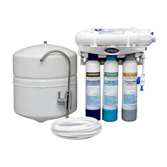
SECTION III: PREPARATION C. Determine System Location A. Major System Components The R.O. system can be located under a sink or in a basement depending on space availability and The following components comprise the R.O. drink- the customer’s preference. ing water system: If a basement installation is selected, additional 1) A reverse osmosis assembly consisting of the tubing, hardware and fittings may be needed and a... -
Page 6: Prepare The Area For Installation
5) Drain Connection - The drain saddle assembly is designed to fit around a standard 1-1/2" OD drain pipe. The drain saddle should always be installed above (before) the trap and on the vertical or horizontal tail piece. Never install the drain saddle close to the outlet of a garbage disposal or plugging of the RO drain line may occur. -
Page 7: Section Iv. Installation Steps
d) Clean up sharp edges with a file if SECTION IV. INSTALLATION STEPS necessary. All plumbing should be done in accordance with PORCELAIN/ENAMEL/CERAMIC ON SHEET state and local plumbing codes. METAL OR CAST IRON BASE: NOTE: Some codes may require installation by a Recommended tools: licensed plumber;... -
Page 8: Mount The Faucet
2. Mount the Faucet: compression nut, plastic ferrule and tube insert. Thread the quick connect fitting securely onto the threaded nipple and firmly insert the 1/4" tubing into the quick connect fitting. B. Install the Feed Water Valve and Tubing The saddle tapping valve supplied is designed for use with 3/8"... -
Page 9: Prefill And Sanitize The Storage Tank
RIGID METAL PIPE AND CPVC PLASTIC PIPE The drain saddle assembly is designed to fit around INSTALLATION: a standard 1-1/2" OD drain pipe. 1) Turn off cold water supply valve and drain the The drain saddle should always be installed above line to prevent spillage. -
Page 10: Install The Ro Membrane
E. Install the R.O. Membrane The tank may be oriented either vertically or horizontally. It is generally placed to the rear of the cabinet but can be set in the front center (between Disconnect the tubing from the end cap of the the sink basins) for ease of access if space permits. -
Page 11: Start Up The System
J. Start up the System 1) Double check that all connections are secure. 2) Open the feed water valve and check for leaks. If any leaks are noted, turn off valve and correct before proceeding. 3) Open the storage tank valve and open the faucet until a steady stream of water flows. -
Page 12: Section V: Operation & Maintenance
Use a drip pan to catch any water that may spill SECTION V. when the filter housings are removed: OPERATION & MAINTENANCE 1) Close plastic supply valve located on the inlet line of the system. A. Normal Operation 2) Close the valve on the inlet of the storage tank. -
Page 13: For Systems Equipped With Quick Connect Fittings
To fix a leak: Relieve pressure Release tubing Cut off at least ¼” from end Reattach tubing Confirm connection is leak free TO ATTACH TUBING... TO RELEASE TUBING... -
Page 14: Section Vi: Troubleshooting Guide
SECTION VI. TROUBLE SHOOTING GUIDE Problem Possible Cause Solution Low quantity of Product Feed water saddle valve is Open valve or unclog. Water from Storage Tank plugged or closed. Clogged sediment pre-filter or Replace filters. activated carbon pre-filter. Low water pressure Feed water pressure must be above 40 psig. - Page 15 Problem Possible Cause Solution High Total Dissolved Feed water pressure must be above Low water pressure. Solids (TDS) in the 40 psig. Product Water R.O. membrane is not fully seated Re-seat the R.O. membrane. in the bottom of the housing. R.O.
- Page 17 QCRO-50 Component Parts List REF # Part Number Description RO-DW-1 Luxury Long Reach Faucet, Non Air Gap, Chrome 4FC4 Faucet Connector, 1/4" tube x 7/16 UNF thread 4SE4 Stem Elbow, 1/4" tube x 1/4" stem IC10Q 2" x 10" Inline Filter, GAC, 1/4" Quick Connect 4SST4 Side Stem Tee, 1/4"...
-
Page 18: Limited Warranty
R.O. DRINKING WATER SYSTEM LIMITED WARRANTY What Does This Warranty Cover? This warranty covers any defects in materials and workmanship of the R.O. Drinking Water System when installed and operated within recommended parameters, with the exceptions stated below. How Long Does The Coverage Last? The manufacturer will warrant its R.O.
Need help?
Do you have a question about the QCRO-50 and is the answer not in the manual?
Questions and answers