
Subscribe to Our Youtube Channel
Related Manuals for Sterling DWSB-TFC-50


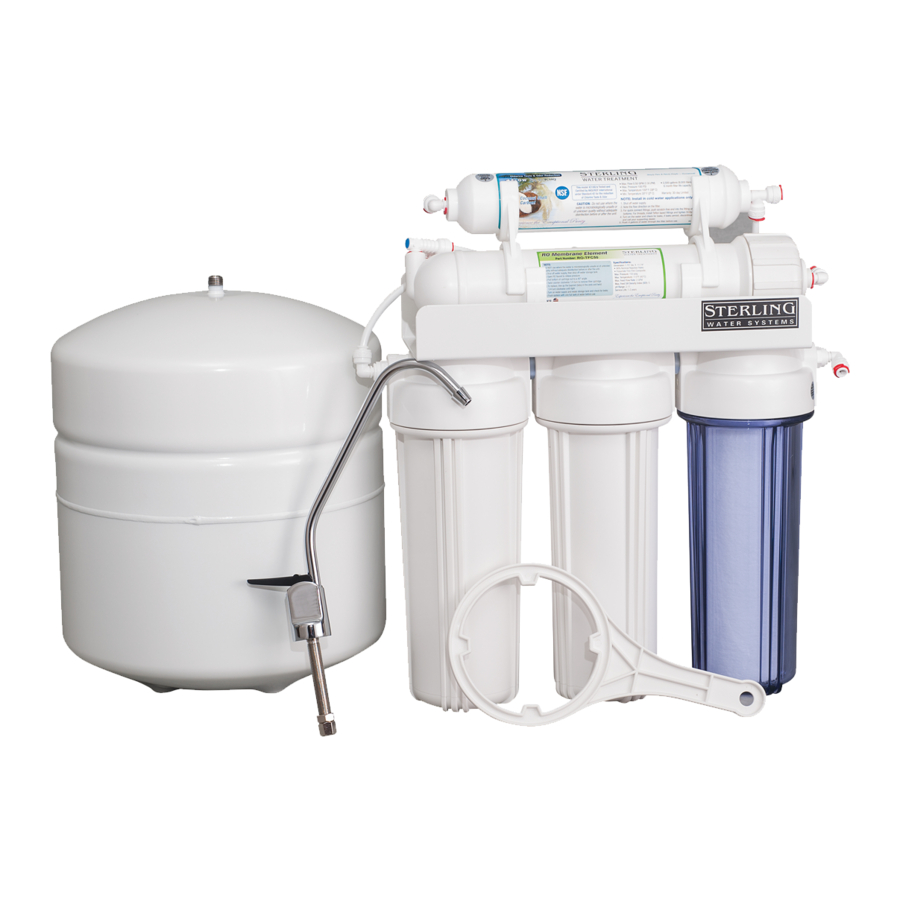
Summary of Contents for Sterling DWSB-TFC-50
- Page 1 INSTALLATION MANUAL DWSB-TFC-50 DWSB-50-PUMP 12630 US 33 N. Churubusco, IN 46723 Ph. (260)693-1972 Fax (260)693-0602 www.sterlingwatertreatment.com...
-
Page 2: Table Of Contents
TABLE OF CONTENTS: SECTION I. INTRODUCTION................3 SECTION II. SPECIFICATIONS..............3 SECTION III: PREPARATION.................4 Major System Components......................4 B. Tools Recommended for Installation..................4 C. Determine System Location......................4 D. Prepare the Area for Installation....................5 E. Prepare the Appliance for Installation..................5 SECTION IV. INSTALLATION STEPS............5 A. -
Page 3: Section I. Introduction
ACTIVATED CARBON PRE FILTERS - The first SECTION I. INTRODUCTION carbon filter contains granular activated carbon which removes chlorine and absorbs organics that Congratulations, you have just purchased one of can damage the membrane. The second carbon the finest Reverse Osmosis Drinking Water filter is a carbon block that has activated carbon Appliances available. -
Page 4: Section Iii: Preparation
TABLE B – RECOMMENDED OPERATING LIMITS FOR FEED WATER Specifications T.F.C. Membrane Water Pressure 40-100 psig (280-690 kPa) 2000 ppm (also mg/l) max. Temperature 40-100°F (4-38°C) 4-11 (optimum rejection at pH 7.0 – 7.5) Hardness Less than 7 gpg (120 mg/l) or soften Iron Less than 0.1 ppm (also mg/l) Manganese... -
Page 5: Prepare The Area For Installation
1) Faucet - The faucet should be placed near arrival. Otherwise, remove supplies from under the the sink where drinking water is normally sink and stack them neatly away from the working obtained. Convenience of use (filling of area. Arrange a light for the work area, if water pitchers and glasses), and an open necessary. -
Page 6: Install The Faucet
A. Install the Faucet b) Slowly drill the required pilot hole for the chassis punch. c) Set up the chassis punch per instructions See Figure 1 for Faucet Installation Diagram and tighten nut to cut the desired hole size. The customer should be consulted before d) Clean up sharp edges with a file if determining faucet location. -
Page 7: Mount The Faucet
2. Mount the Faucet: SOFT COPPER TUBING INSTALLATION: a) Familiarize yourself with all components shown in faucet diagram. 1) Turn off cold water valve under the sink, or b) Disassemble hardware from the threaded main valve for the house. nipple, except for chrome base plate and 2) Before installing saddle tapping valve, make rubber washer. -
Page 8: Install The Drain Connection
require filling with water for 15 minutes to be completely sanitized. It is important to use a sanitizer when pre-filling tank so the solution can sanitize the tubing, fittings, and faucet at the time of installation and startup. 1) Insert free end of feed water tubing into the fitting on the storage tank. -
Page 9: Make Initial Tubing Connections
F. Make Initial Tubing Connections I. Install Ice Maker Hookup (optional) It is advantageous to make some of the tubing connections at this time, since the under-sink work Note: Check with refrigerator manufacturer for area is not so cramped and access to the compatibility with your refrigerator model. -
Page 10: Section V: Operation & Maintenance
Proceed to check reject flow rate by the system is not used for 3-4 weeks or longer, it is disconnecting tubing at drain connection a good idea to re-sanitize the system and to and measure as per above. The ratio change the Activated Carbon and Sediment Filters. - Page 11 h) At the end of the 15 minutes, in the drops of bleach (this is ½ tsp. or 3 ml) into following order, close the saddle tapping the tubing and reconnect it. valve, close the holding tank valve, and k) Slowly open the saddle tapping valve. When open the dispensing faucet to release the water begins dripping out of the dispensing pressure.
-
Page 12: For Systems Equipped With Quick Connect Fittings
TO ATTACH TUBING... C. For System Equipped with Quick Connect Fittings Your new Reverse Osmosis Drinking Water Appliance may be outfitted with new generation of user-friendly quick connect push-in fittings. Proper use of the fittings is shown in the diagrams. It is important that the tubing selected for use with these connectors be of high quality exact size and roundness, and with no surface nicks or scratches. -
Page 13: Section Vi: Troubleshotting Guide
SECTION VI. TROUBLE SHOOTING GUIDE Problem Possible Cause Solution Low quantity of Product Feed Water Saddle Valve is Open Valve or unclog. Water from Holding Tank plugged or closed. Clogged Sediment Prefilter or Replace filters. Activated Carbon Prefilter. Low water pressure Feed Water pressure must be above 40 psig. - Page 14 Problem Possible Cause Solution High Total Dissolved The Product Water and Drain Correct plumbing. Solids (TDS) in the Water lines are reversed. Product Water (continued) No drain flow, Drain Restrictor is Clear or replace Drain Restrictor. clogged. No drain flow, the drain orifice in Clear or replace Dispensing Faucet.
-
Page 15: Limited Warranty
R.O. DRINKING WATER SYSTEM LIMITED WARRANTY What Does This Warranty Cover? This warranty covers any defects in materials and workmanship of the R.O. Drinking Water System when installed and operated within recommended parameters, with the exceptions stated below. How Long Does The Coverage Last? The manufacturer will warrant its R.O.
Need help?
Do you have a question about the DWSB-TFC-50 and is the answer not in the manual?
Questions and answers