Table of Contents
Advertisement
Quick Links
™
™
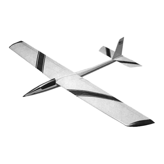
•Hand-launch sailplane for thermal or slope flying
•Flat wing with ailerons for ultimate maneuverability
•Rugged, lightweight balsa/ply construction
•Optional V-tail version
READ THROUGH THE PRELIMINARY INFORMATION BEFORE YOU START
BUILDING. IT CONTAINS IMPORTANT INSTRUCTIONS, WARNINGS, AND
INFORMATION CONCERNING THE BUILDING AND USE OF THIS MODEL.
Instruction Manual
WARRANTY
Dynaflite guarantees this kit to be free from defects in both material and workmanship at
the date of purchase. This warranty does not cover any component parts damaged by use
or modification. In no case shall Dynaflite's liability exceed the original cost of the
purchased kit. Further, Dynaflite reserves the right to change or modify this warranty
without notice. In that Dynaflite has no control over the final assembly or material used for
final assembly, no liability shall be assumed nor accepted for any damage resulting from
the use by the user of the final user-assembled product. By the act of using the user-
assembled product, the user accepts all resulting liability. If the buyer is not prepared
to accept the liability associated with the use of this product, return this kit
immediately in new and unused condition to the place of purchase.
TALNP02 Printed in USA
© Copyright 2000 V:1.3
Advertisement
Table of Contents

Related Manuals for Dynaflite Talon


Summary of Contents for Dynaflite Talon
-
Page 1: Instruction Manual
Further, Dynaflite reserves the right to change or modify this warranty without notice. In that Dynaflite has no control over the final assembly or material used for final assembly, no liability shall be assumed nor accepted for any damage resulting from the use by the user of the final user-assembled product. -
Page 2: Table Of Contents
Make the stab mount ........9 Build the stab..........9 Prepare the stab and fin for joining to the fuse Your Talon is not a toy, but a sophisticated BUILD THE WING ........12 working model that functions like a full-size Build one wing panel ........12 sailplane. -
Page 3: Precautions
(stamped on the end of the carton) and have them ready when you call.We can also be reached by E-Mail at: PRECAUTIONS productsupport@dynaflite.com 1. You must assemble the model according to PREPARATIONS the instructions. Do not alter or modify the model, as doing so may result in an unsafe or unflyable model. -
Page 4: Required Building Supplies And Tools
5-1/2" Bar Sander (GPMR6169) 11" Bar Sander (GPMR6170) These are the building tools and supplies that 22" Bar Sander (GPMR6172) you will need to build your Talon. We 33" Bar Sander (GPMR6174) recommend Great Planes Pro™ CA and Epoxy 44" Bar Sander (GPMR6176) 11"... -
Page 5: Build The Fuselage
7 . Drill a 3/16" hole through the center of former is over a flat building board that you can stick 1. After your Talon is completed, this will allow pins into. Cover the top view of the fuse with you to add lead shot to the compartment in the Great Planes Plan Protector or wax paper. - Page 6 sides of the formers are on the left side of the fuse, glue the formers to the fuse bottom with thin CA. As you proceed, use a small building square to keep the formers perpendicular to your building board. 9. Position one of the die-cut 3/16" balsa upper fuse sides over the side view of the fuse plan, aligning the front where indicated on the plan.
-
Page 7: Finish Framing The Fuselage
18. Position the tail block between the upper 6. Glue the 1/8" x 1-1/4" x 30" balsa fuse top to fuse sides 4" aft of former 6. Make sure the notch the fuse with medium or thick CA. The aft edge of in the tail block is on the left side and glue it the fuse top should extend 1/2"... -
Page 8: Make The Hatch
2. Use a razor saw to cut the aft end of the hatch along the lines you previously marked. Cut the front of the hatch at an angle 11" from the aft end of the hatch. 11. Cut the front of the fuse until the 1/2" x 1/2" x 1/2"... -
Page 9: Build The Tail Surfaces
4. Use steel wool, sandpaper or a wire brush to BUILD THE TAIL SURFACES remove corrosion and clean the solder joint holding the horn to pre-bent stab joiner wire. If necessary, use a small file to true up the solder joint so both brass bushings can slide up close to the horn. - Page 10 3. Note the location of the arm portion of the joiner wire. This determines the true location of 1/16" x 1/4" Stab Spars the 1/8" x 1/8" balsa rib —not necessarily where it is shown on the plan. (You can see in the photo Trim how the rib on our model needed to be moved inward a bit).
-
Page 11: Prepare The Stab And Fin For Joining To The Fuse
4. Glue the balsa stab mounts together with the joiner wire in between. Make sure you have the joiner wire facing the right way and make sure you glue the bearing tubes to the mounts, but refrain from getting glue inside the bearing tubes. 9. -
Page 12: Build The Wing
desired thickness of the trailing edge of the 7. Remove the stab halves from the joiner wire. aileron. As shown in the photo, the guideline can Solder a metal clevis to the braided wire elevator be most easily drawn by laying your pen and the pushrod cable that came in your pushrod kit. - Page 13 11. Place the 1/8" x 3/8" x 24" balsa sub trailing edge (TE) up against the ribs over its location on the plan. Pin a straightedge to the plan tightly up against the sub TE to hold it in position. Trim any ribs as necessary to make sure the sub TE will remain straight.
-
Page 14: Finish The Wing Panel
19. Glue a die-cut 3/32" balsa gusset to both sides of rib 2 and the sub trailing edge. Glue an additional gusset to rib 9 and the sub trailing edge. This gusset is not shown on the plan and you’ll have to trim it to fit. 20. - Page 15 wing with masking tape until the glue dries (about an hour should be sufficient). 4. Use your razor plane followed by a bar sander with 80-grit sandpaper to blend the LE to the top and bottom skins. Do not round the LE until you are instructed to do so after you join the two halves together.
-
Page 16: Join The Wing
JOIN THE WING You may build your wing flat or with dihedral. CUT HINGE SLOT If you build the wing flat your Talon will have WITH HOBBY KNIFE more maneuverability. If you build your wing AND #11 BLADE with dihedral your Talon will have more stability. -
Page 17: Join The Wing
3. Test join your wing halves with your homemade wing joiner. Use your bar sander to sand the ends of 1/8" Notch the wing as necessary so they will fit at the correct angle. 4. Use a piece of wire or something similar to thoroughly apply 30-minute epoxy to the spars inside one wing half and to the top and bottom edges of one half of the wing joiner. -
Page 18: Mount The Wing To The Fuselage
CA but we prefer 30-minute epoxy. Whatever 6. After the epoxy from the previous step has adhesive you use, just make sure the cloth is fully cured, remove the wing. Glue the dowel to thoroughly saturated and is securely bonded to the the bottom of the wing with more epoxy. -
Page 19: Mount The Hatch
15. Cut a small, round hole in the fuse bottom to countersink the head of the nylon wing bolt. Hint: Use a 13/32" brass tube sharpened at one end to cut the hole. 10. Securely glue the bottom wing bolt block to the aft edge of former 2 and the bottom of the fuse. -
Page 20: Mount The Stab And Fin To The Fuselage
MOUNT THE STAB AND FINAL CONSTRUCTION FIN TO THE FUSE These following instructions apply to you V-tail MOUNT THE SERVOS builders, too. 1. Temporarily position the stab mount on the fuse with both stab halves. With the wing bolted to the fuse, view the model from the rear to make sure the stab aligns horizontally with the wing (it’ll be a little trickier to see the V-tail stab alignment with the wing, but it’s the same idea). -
Page 21: Cover Your Model
servo horn to your elevator servo and secure it Regular iron-on films intended for larger models with the screw. may shrink too much, damaging or warping your structure. 5. Position your elevator servo in the fuselage. Make servo holders for the elevator servo as Fuse covering sequence shown on the plan from leftover 1/8"... -
Page 22: Get Your Model Ready To Fly
TO KEEP HINGE CENTERED 2. Join the aileron to the wing with the hinges. 3. Lift your Talon at the balance point (or place it If you cannot get the hinges to remain centered, on a Great Planes C.G. Machine ™... -
Page 23: Mount Your Receiver And Battery
Remember to adjust your charge rate for smaller battery packs. FLYING Since the Talon is a model intended for modelers with previous R/C experience in slope soaring or GROUND CHECK YOUR hand launching, we will assume you already have the knowledge necessary to fly this model and won’t... - Page 24 After Once you have your Talon trimmed and the C.G. your model is C.G.’d correctly and ready to fly, is set, you’re ready for the slopes! take it out to your flying field. Turn your transmitter and receiver on and toss your Talon at a level attitude straight into the wind.
Need help?
Do you have a question about the Talon and is the answer not in the manual?
Questions and answers