Table of Contents
Advertisement
8 8
4 4
" "
F F
8 8
4 4
" "
F F
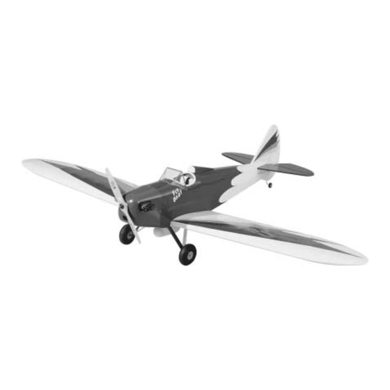
• HUGE, 84" WINGSPAN (IMAA Legal)
• 1/4 SCALE MODEL
READ THROUGH THIS INSTRUCTION MANUAL FIRST. IT CONTAINS
IMPORTANT INSTRUCTIONS AND WARNINGS CONCERNING THE ASSEMBLY
AND USE OF THIS MODEL.
Dynaflite guarantees this kit to be free from defects in both material and workmanship at the date of
purchase. This warranty does not cover any component parts damaged by use or modification. In no
case shall Dynaflite's liability exceed the original cost of the purchased kit. Further, Dynaflite reserves
the right to change or modify this warranty without notice. In that Dynaflite has no control over the
final assembly or material used for final assembly, no liability shall be assumed nor accepted for any
damage resulting from the use by the user of the final user-assembled product. By the act of using
the user-assembled product, the user accepts all resulting liability. If you are not prepared to accept
the liability associated with the use of this product, return this kit immediately in new and unused
condition to the place of purchase.
FLYBP03 for DYFA3030 Printed in USA
™
u u
n n
S S
c c
u u
n n
S S
c c
• REALISTIC FUN SCALE MODEL
WARRANTY
™
a a
l l
e e
F F
a a
l l
e e
F F
• BUILDS QUICKLY
Instruction Manual
l l
y y
B B
a a
l l
y y
B B
a a
Entire Contents © Copyright 1997
b b
y y
b b
y y
Advertisement
Table of Contents

Related Manuals for Dynaflite DYFA3030


Summary of Contents for Dynaflite DYFA3030
-
Page 1: Instruction Manual
Instruction Manual WARRANTY Dynaflite guarantees this kit to be free from defects in both material and workmanship at the date of purchase. This warranty does not cover any component parts damaged by use or modification. In no case shall Dynaflite's liability exceed the original cost of the purchased kit. Further, Dynaflite reserves the right to change or modify this warranty without notice. -
Page 2: Table Of Contents
Build the Rudder..........8 Build the Stabilizer ..........9 At Dynaflite we take pride in offering kits that are Build the Elevators ..........9 simple and straightforward to build and provide Build the Wing............9 value for your modeling dollar. -
Page 3: Precautions
PRECAUTIONS PROTECT YOUR MODEL, YOURSELF & OTHERS... FOLLOW THIS IMPORTANT 1. You must assemble the plane according to the instructions. Do not alter or modify the model, as SAFETY PRECAUTION doing so may result in an unsafe or unflyable model. In a few cases the instructions may differ slightly from the photos or plan. -
Page 4: Preparations
SUGGESTED SUPPLIES PREPARATIONS We recommend Great Planes Pro CA and Epoxy ™ 4 oz. Thin CA Adhesive - (GPMR6004) REQUIRED ITEMS 4 oz. Medium CA Adhesive (GPMR6010) 2 oz. Thick CA Adhesive - (GPMR6015) These are the items “not included“ with your kit; you CA Accelerator - (GPMR6035) will need to purchase them separately. -
Page 5: Building Notes
Epoxy - 6-minute epoxy cures the fastest; it sets BUILDING NOTES within six minutes but is not fully cured for one hour or more. 30-minute epoxy is the strongest as it allows the epoxy to soak into the wood • When you see the term “cut and fit” in the thoroughly. -
Page 6: Die Patterns
DIE-PATTERNS... -
Page 7: Die Patterns
DIE-PATTERNS... -
Page 8: Build The Tail Group
BUILD THE RUDDER BUILD THE TAIL GROUP BUILD THE FIN 1. Laminate the two 1/8" die-cut rudder TE1 pieces together. Do the same for the TE2 pieces. Glue the TE1 and TE2 pieces together over the plan. After they are dry remove them from the plan. 2. -
Page 9: Build The Stabilizer
BUILD THE STABILIZER BUILD THE ELEVATORS 1. Laminate two of the 1/8" die-cut balsa elevator trailing edge pieces together for each elevator. 1. Place the stab and elevator plan on your work surface and cover it with wax paper. 2. From a 3/8"x 5/8"x 30" balsa stick, cut the elevator leading edge and also the root end of the 2. - Page 10 7. Glue the 1/4" x 3/8" x 36" basswood top spar into place. 2. Glue the die-cut 1/8" ply W1D and W2D doublers to four W3 ribs with 6-minute epoxy as shown in the photo. NOTE: The W1D landing gear notch is deeper than the notch in W2D.
- Page 11 17. Fit and glue the 3/32" x 1/2" x 36" 12. Glue WTR1 and W5 to the spars keeping balsa TE spar sheeting onto the bottom of the ribs WTR1 down against the 1/2" shim. It will be from W1 to W5. necessary to squeeze and hold the spars together until the glue cures.
- Page 12 21. Fit and glue the 3/32" x 1/2" x 36" balsa TE spar sheeting onto the top of the ribs and the rear webs from rib W1 to rib W5 using medium CA. 22. Taper the lower TE sheeting to the contour of the top of the ribs.
- Page 13 30. Fit and glue the laminated WT1 to the center of rib W5 and in the notches of W6 and 33. From a 3/32" x 3/8" x 30" balsa stick, WTR1. cut, fit and glue the cap strips to rib W6 and WTR1 between ribs W5 and W6.
-
Page 14: Join The Wing Halves
3. Without using any glue, join the wing halves with the dihedral braces. Place the wing on the support block upside down. The tops of the W5 ribs should just touch the building board. Make adjustments as necessary. 36. Glue the 1/8" die-cut ply dowel support in place to the back of the leading edge between NOTE: The dihedral angle is 3-1/2 degrees for each ribs W1 and W2. - Page 15 6. Use two 21" x 4" pieces of paper to roll into paper tubes. Slip these into the holes in the wing ribs to form a conduit for the servo wires. 9. Glue the hardwood landing gear block into place with 6-minute epoxy. 10.
-
Page 16: Build The Ailerons
4. Fit and glue the hinge blocks in place using BUILD THE AILERONS leftover 1/4" x 3/4" balsa. 1. Shape the LE of the aileron from a 1/4" x 3/4" x 24" balsa stick using the TE of the wing as a 5. - Page 17 2. Glue F2D to F2 with medium CA. 5. Locate the two 1/8" x 1/2" x 42" balsa top longerons. Glue one to the inside of the left fuse side along the top edge beginning 3/8" back from the 3. Laminate the three F1 firewalls with 30-minute epoxy. front.
- Page 18 12. From the 1/4" x 3/8" x 36" basswood stick, cut and glue doublers in place behind the firewall using 30-minute epoxy. After the epoxy has cured you may want to pin the firewall to the fuselage with small dowels or toothpicks for additional security. Drill several small holes through the sides and into the firewall.
- Page 19 earlier, glue formers F4, F5, F6 and F7 into place. Check to insure that the fuselage remains straight and square. 16. Note the angle of the instrument panel on the plan and glue it into place. 21. Using the 1/8" x 3" x 24" balsa sheets, sheet the front top of the fuselage as shown in the photo.
-
Page 20: Final Assembly
30-minute epoxy. Glue some doublers to the blocks and fuselage sides using leftover 1/4" x 3/8" basswood. 26. Two 1/8" x 1/4" x 36" balsa sticks are included with the kit. If desired, these can be glued to the flat fuselage sides as stringers so that the covering will give the fuselage a more rounded appearance. - Page 21 10. Glue the 3/4" x 1" x 6" basswood landing gear block into place with 30-minute epoxy. Make sure it is glued to former F2. 6. Align the wing squarely on the fuselage. This is easily done using a piece of string as a guide. Put a pin in the tail of the fuselage at the centerline.
- Page 22 14. Use the remainder of the 3/8" x 15/16" stick to make a fairing between the bottom of the wing and former F2. 15. You can now glue the stab and fin to the fuselage. To increase the gluing area, glue some leftover 3/8"...
- Page 23 using CA to hold them in place. Apply glass cloth to glass the fairings to the wire and to each other as shown. Use Bondo filler to blend the assembly. The ® gear should be ready to prime and paint but hold off until the cowl is ready.
-
Page 24: Finishing
strip of plastic that is used to reinforce the joint on balance. If not you may want to consider putting the the inside. Thin CA works well for this. Fill in the radio in the tail. With other engines place the servos joints with Bondo or a similar filler. -
Page 25: Set The Control Throws
If the servos are mounted just aft of the firewall, you 5. Mount the wheels. will need a pushrod system 42" long. If the servos are mounted at the TE of the wing, you will need a 6. Hinge the rudder, elevators and ailerons with the pushrod system 28"... -
Page 26: Balance The Model
BALANCE THE MODEL PREFLIGHT This section is important and must not be omitted. A AT HOME model that is not properly balanced will be unstable and possibly unflyable. Balance Your Propellers Balancing the propeller seems like one of those 1. Check the balance point with all components things that you can skip, but many problems are the installed in the model and the fuel tank empty. -
Page 27: Engine Safety Precautions
Keep loose clothing, shirt sleeves, ties, scarfs, long thing you always must do is make sure no one else is on your frequency (channel). Most model flying hair or loose objects away from the prop. Be fields utilize frequency control so familiarize yourself conscious of pencils, screwdrivers or other objects with their system. -
Page 28: Takeoff
parks, school yards, office building lawns, etc. that FLYING may attract unrestrained observers (wild kids). If you are a beginner, you are busy enough concentrating on The design of the Fly Baby aircraft originated in your model without having to answer lots of questions model aviation of the early 1930’s, an era when and performing crowd control.
Need help?
Do you have a question about the DYFA3030 and is the answer not in the manual?
Questions and answers