Table of Contents
Advertisement
Quick Links
READ THROUGH THIS INSTRUCTION MANUAL FIRST. IT CONTAINS
IMPORTANT INSTRUCTIONS AND WARNINGS CONCERNING THE ASSEMBLY
AND USE OF THIS MODEL.
Dynaflite guarantees this kit to be free from defects in both material and workmanship at the
date of purchase. This warranty does not cover any component parts damaged by use or
modification. In no case shall Dynaflite's liability exceed the original cost of the purchased kit.
Further, Dynaflite reserves the right to change or modify this warranty without notice. In that
Dynaflite has no control over the final assembly or material used for final assembly, no liability
shall be assumed nor accepted for any damage resulting from the use by the user of the final
user-assembled product. By the act of using the user-assembled product, the user accepts all
resulting liability. If the buyer is not prepared to accept the liability associated with the use of
this product, return this kit immediately in new and unused condition to the place of purchase.
CHPGP03 Printed in USA V1.0
• BUILDS QUICKLY
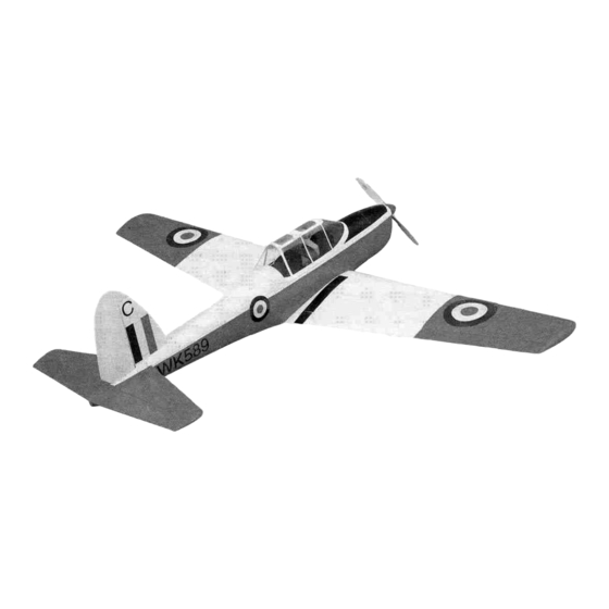
• REALISTIC FUN SCALE® MODEL
• HUGE, 89" WINGSPAN (IMAA Legal)
WARRANTY
Instruction Manual
Entire Contents © Copyright 2000
Advertisement
Table of Contents

Subscribe to Our Youtube Channel
Related Manuals for Dynaflite CHIPMUNK


Summary of Contents for Dynaflite CHIPMUNK
-
Page 1: Instruction Manual
Instruction Manual WARRANTY Dynaflite guarantees this kit to be free from defects in both material and workmanship at the date of purchase. This warranty does not cover any component parts damaged by use or modification. In no case shall Dynaflite's liability exceed the original cost of the purchased kit. -
Page 2: Table Of Contents
R/C pilot. Congratulations on your choice of this kit for Remember: Take your time and follow your next project. The Chipmunk is a Fun Scale® model of a true classic aircraft. It has the instructions to end up with a well-built presence that only a big model can carry off. -
Page 3: Preparations
To make your R/C modeling experience totally enjoyable, get assistance with assembly and your first flights from an Your Chipmunk is not a toy, but a sophisticated working model that functions very much like an experienced, knowledgeable modeler. -
Page 4: Optional Accessories
convenience. GPM is the Great Planes® brand, -(5) 4-40 Metal Solder Clevis (Seven with TOP is the Top Flite® brand and HCA is the Flaps) (GPMQ3814) Hobbico® brand. - (5) 4-40 Hex Nuts (Seven with Flaps) (GPMQ3304) 4-6 Channel Radio with One Standard Servo - (2) 4-40 x 12"... -
Page 5: Building Notes
the pieces as you cut them for later reference. By doing this now, you won't have to splice pieces together later. ADHESIVES This kit is built with three types of glue. Cyanoacrylate: CA glues cure almost instantaneously and are moderately strong. There are different A flat, durable, easy-to-handle sanding tool is a viscosities of CA's intended for different necessity for building model airplanes. -
Page 6: Common Abbreviations
minute epoxy is the strongest as it allows the the parts to be glued with accelerator, join them, then add the CA. This way the CA is epoxy to soak into the wood thoroughly. While guaranteed cure immediately. This itsets within 30 minutes, it is not fully cured for prepriming is especially handy when you use two or more hours. -
Page 7: Die-Cut Patterns
Die-Cut Pattern Note: If you will be building functional flaps for your Chipmunk, glue in the lightening holes in ribs W4 and W5. CHPGIPW06 1 REQ. Note: This page shows the location of the die-cut parts for the wing. Not all parts are marked on the die sheets. -
Page 8: Die-Cut Patterns
Die-Cut Pattern CHPGF05 1 REQ. 1/8" X 3" X 36" BALSA CHPGF04 2 REQ. 1/8" X 3" X 36" BALSA CHPGF03 1 REQ, 1/8" X 6-3/8" X 25-1/4" PLY CHPGF02 1 REQ. TOP DECK 1/8" X 6-3/8" X 25-1/4" PLY CHPGF01 2 REQ. -
Page 9: Build The Stabilizer & Elevators
STAB SHEETING 1/16"X3"X30" USE LEFTOVER BALSA SHEETING FOR FIN SHEETING 1. Cut the stabilizer drawing from the fuselage plan and place it on your building board. Cover the plan with Great Planes Plan Protector. Q7. Sheet the stab with 1/16" x 3" x 30" balsa on both the top and bottom. -
Page 10: Build The Vertical Fin & Rudder
Q 16. Notch the LE of both elevators where shown on the plan and fit and glue the die-cut 1/8" ply horn bases into place. Q 17. Remove the elevators from the plan and rough sand them to the shape shown in the cross-section. - Page 11 5. Cut and fit the ribs from the remainder of Q 10. Cut the rudder base from the rest of the the 3/16" x 3/8" x 24" balsa. Cut the longer ribs 1/2" x 15/16" balsa. Glue and pin it into place. first.
-
Page 12: Build The Fuselage
Q 1.The fuselage plan is in two pieces. Cut the plan as indicated and tape the two parts together. Cut the fuselage top view from the plan. Cut the drawings for bulkheads B, C, D, F and H from the plan. Place the bulkhead [-I 3. - Page 13 CUT ALONG EMBOSSED LINE RIGHT FUSE SIDE [-] 7. Locate one of the die-cut 1/8" ply forward I-J10. Place the right fuselage side over the plan fuselage sides. Cut off the front end of this side along the embossed line.This will establish two and mark the locations of bulkheads B, C, D, E, degrees of right thrust.
- Page 14 t_] 15. Lightly sand the sides of bulkheads F and H to match the slope of the sides. Install them in their proper locations in the fuselage sides and hold them in position with pins. Do NOT glue until later. Q 12.
- Page 15 fuselage side view as a guide. These mount Q 19. Cut a stringer from 1/8" x 1/4" x 31" blocks are glued to the bottom longeron at an basswood to length and glue into place to the angle to conform to the curve on bottom bottom of formers AB and BB.The remainder of formers HTW and JTW.
- Page 16 you will be using the Great Planes Isolation Mount™ you will need to reposition the Mounting Grommets as shown on the plan. Note: Depending on the type of engine you are installing, you may need to add spacers between the engine mount and firewall. Layers of aircraft grade 1/4"...
- Page 17 Note: If you will be entering your Chipmunk in IMAA events you need review their requirements for servo and control linkage sizes. They require high-torque servos on control surfaces and 4-40 size control linkages, with metal clevises. Q 33, Glue the die-cut 1/8" ply and balsa top bulkhead formers AT, BT, IP, (2) CT and (2) DT into position.
- Page 18 1-1 37. Glue two sheets of 1/8" x 3" x 24" balsa Q 40. Use some more leftover 1/8" balsa together to form a sheet 6" wide. Sand the outer sheeting to cut, fit and glue filler strips between side of this sheet flat and smooth. Cut, fit and the side sheeting and the ply fuselage sides at glue this sheet into position to the left fuselage the wing saddle area.
-
Page 19: Build The Wing
Check the fit of the spar to the spar notches in each rib. Note: If you will be building functional flaps for your Chipmunk, glue in the rear lightening holes in ribs W4 and W5. TOP WING SKIN 3/32"... - Page 20 plan. There are two doublers for W2. The one Q Q 9. Glue the 1/4" x 3/8" x 44" basswood top with the long cutout is glued to the side facing spar to the ribs. the wing root. This cutout will lock in the landing gear stub (torque) block.
- Page 21 Q Q 16. Glue a 3/32" x 15/16" x 24" balsa TE 13. Glue the 1/4" x 1/2" x 48" balsa leading sheet to the inner TE and ribs using aliphatic edge stick to the front of the ribs. Align the top of the LE even with the tops of the ribs.
- Page 22 1—1 19. Glue the leading edge skin that you Ql [-1 24. Glue the landing gear's 5/8" x 1" x 1" prepared in step 2 to the top spar, ribs and LE maple stub block to W2 using 30-minute epoxy. using aliphatic resin.
-
Page 23: Join The Wing Panels
U U 27. Using a 1/4" bit, drill a hole through the landing gear rail into the stub block. Radius the top of the hole to fit the bend in the 1/4" landing gear wire. (See the photo at step 26.) U U 1. - Page 24 but it is a bit harder to install this way. Do not sheet the bottom center section at this time. Q 6. Glue the die-cut 1/8" ply LE doublers to the rear of the LE between W1 andW2 on both wing panels.
- Page 25 3/32" x 3" balsa.This gives the covering a place to adhere to. Oil-] 17. If you are installing flaps on your Chipmunk, Q 13. Using the leading edge wing skins you prepared earlier, sheet the bottom LE of both build the flap servo mount between ribsW4 and wing panels.
-
Page 26: Build The Ailerons
plan as a guide to cut the sheeting to the proper Q Q 3. Cut the LE from 1/4" x 3/4" x 24" balsa. size. Glue this piece to the tops of the ribs. Sand the bottom of the LE to match the angle of the aileron ribs at their LE. -
Page 27: Build The Flaps
[-I Q 12. Cut four additional hinge blocks from Q [-I 7. Remove the flap from the plan. Carve the 1/4" x 1/2" balsa. Glue these into position in and sand the top of the LE to match the contour theTE of the wing opposite the position of the of the ribs. -
Page 28: Mount The Wing To The Fuselage
Q Q 12. Cut four additional hinge blocks from the 1/4" x 1/2" balsa. Glue these into position in theTE of the wing opposite the position of the blocks in the flap. Q 13. Return to step one (1) and build the left flap. [-.I 2. -
Page 29: Finish The Fuselage
[-I 12. Glue doubler DB to the front of bulkhead Q 5. Fit the two die-cut 1/8" ply wing bolt plates D. Align DB 3/32" above (towards the top of the for the wing bolt holes onto the bottom of the wing. - Page 30 SIDE SHEETING 1.1/4" 5" 13-1/2" 2-1/2" 31" 3" 36"" Q 2. Add a stringer to the fuselage from former DT to HT. Use the supplied 3/16" x 3/16" x 24" balsa sticks. Cut notches in top formers DT, ET, FT, GT and HT, and add a stringer to each side as shown in the photo above.
- Page 31 clevis (GPMQ3814) at the rudder end and a 4-40 metal threaded clevis (GPMQ3794) at the servo end with a 4-40 hex nut. CJ 11. Fit the horizontal stab to the fuselage. To do this you will need to cut a slot in the stab for the rudder torque rod.
- Page 32 room table for the next steps. Just make sure to Q 18. When the epoxy has cured remove the cover the table so you don't scratch it or get wing. Bring the model back to your workbench glue on it, lest - well, you get the idea. with thanks for the use of the table.
-
Page 33: Final Assembly
Q 1. Finish the cockpits. The cockpit area was designed to be structure free so you can add as much detail as desired.The simplest is to glue a couple of Williams Brothers pilots to the top deck. The kit includes two instrument panel decals which can be positioned on the front instrument panel and rear former CT, or you can fashion separate instrument panels. - Page 34 DRILL A 3/32" HOLE CUT HINGE SLOT 1/2" DEEP, IN CENTER WITH HOBBY KNIFE OF HINGE SLOT AND #11 BLADE D. Use a hobby knife with a #11 blade to B. Drill a 3/32" hole in the center of all the make the hinge slots.The first cut should hinge slots to allow the CA to fully be a shallow slit to establish the hinge...
-
Page 35: Finishing
to wipe away excess CA. If you spill a few While this is a large aircraft, it does not fly very drops of CA on the MonoKote® film you fast. We have found that the above installation can use CA Debonder (GPMR6039) to remove has worked very well. -
Page 36: Set The Control Throws
Q 9. Mount the landing gear and 4" wheels (ROBQ1537). Note: Optional landing gear struts are available from Robart that fit this model. These struts not Measure the throws at the widest part of the only add a nice touch to the model but help trailing edge of the rudder, elevator, flaps and absorb landing stresses as well. -
Page 37: Balance The Model Laterally
We use a tail of the Chipmunk to achieve balance, use Great Top Flite Precision Magnetic Balancer'" (TOPQ5700) Planes Self Adhesive Lead Weights (GPMQ4485). -
Page 38: At The Flying Site
arm onto the servos and the servo cords are securely connected to the receiver. If you are not thoroughly familiar with R/C models, ask an experienced modeler to inspect your radio installation and make sure the control surfaces Note: Failure to follow these safety precautions respond correctly. -
Page 39: Ama Safety Code (Excerpt)
Make all engine adjustments from behind the 9. I will not operate models with pyrotechnics rotating propeller. (any device that explodes, burns, or propels a projectile of any kind). The engine gets hot! Do not touch the engine RADIO CONTROL during or immediately after you operate it. -
Page 40: Takeoff
An experienced modeler can accelerated to a safe flying speed. Make your take your Chipmunk up for the first time and first turn away from the spectator and pit area. make sure it performs correctly, then give you valuable flight instruction. - Page 41 Center Pull...
- Page 42 TWO VIEW DRAWING Use copies of this page to plan your trim scheme -Out Page...
Need help?
Do you have a question about the CHIPMUNK and is the answer not in the manual?
Questions and answers