Advertisement
Quick Links
READ THROUGH THIS INSTRUCTION MANUAL FIRST. IT CONTAINS
IMPORTANT INSTRUCTIONS AND WARNINGS CONCERNING THE ASSEMBLY
AND USE OF THIS MODEL.
Instruction Manual
Dynaflite guarantees this kit to be free from defects in both material and workmanship at the date of
purchase. This warranty does not cover any component parts damaged by use or modification. In no
case shall Dynaflite's liability exceed the original cost of the purchased kit. Further, Dynaflite reserves
the right to change or modify this warranty without notice. In that Dynaflite has no control over the
final assembly or material used for final assembly, no liability shall be assumed nor accepted for any
damage resulting from the use by the user of the final user-assembled product. By the act of using
the user-assembled product, the user accepts all resulting liability. If you are not prepared to accept
the liability associated with the use of this product, return this kit immediately in new and unused
condition to the place of purchase.
WANDP03 Printed in USA
TM
• Simple Entry Level Construction
• Stable Flight Characteristics
• Excellent R/C Trainer
WARRANTY
TM
MADE IN
Advertisement

Subscribe to Our Youtube Channel
Related Manuals for Dynaflite Wanderer


Summary of Contents for Dynaflite Wanderer
-
Page 1: Instruction Manual
AND USE OF THIS MODEL. Instruction Manual WARRANTY Dynaflite guarantees this kit to be free from defects in both material and workmanship at the date of purchase. This warranty does not cover any component parts damaged by use or modification. In no MADE IN case shall Dynaflite's liability exceed the original cost of the purchased kit. -
Page 2: Table Of Contents
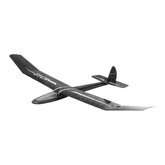
The 72" version of the Wanderer was developed by Mark Smith as a first-time building and flying project. Since its introduction in 1975, over 85,000 kits have been produced. Over the years the Introduction............2 Wanderer has been updated with many changes Precautions............3... -
Page 3: Required Items
3. You must install all R/C and other components so Flite® brand, HCA is the Hobbico® brand and DYN that the model operates properly on the ground and is the Dynaflite™ brand. in the air. 2 - 4 channel radio with two standard servos. - Page 4 SUGGESTED BUILDING SUPPLIES, CON'T. Hobby Knife (HCARO 105) #11 Blades Pliers (Common and Needle Nose) Screw driver (Phillips) T-pins(HCAQ5150) 60" Retractable Tape Measure (HCAR0478) Great Planes Easy-Touch Bar Sanders are made Straightedge With Scale from lightweight extruded aluminum and can be found at most hobby shops.
-
Page 5: Preparations
• Whenever the instructions tell you to glue pieces together, thin CA should be used. When a specific type of glue is required, the instructions will state the type of glue that is highly recommended. When 30-minute epoxy is specified, it is highly recommended that you Airfoil: A curved structure designed to create lift by use only 30-minute (or slower) epoxy because the reaction to air moving over its surface. - Page 6 Sailplane: An airplane which flies without an engine. Sailplanes are designed to ride on warm, rising air currents, called thermals. Sailplanes are launched by several methods: a giant sling shot called a high-start; a winch which pulls the sailplane up like a kite; or with the assistance of a small engine or electric motor.
- Page 7 Die-Cut Layout INNER PANEL GUSSETS OUTER PANEL GUSSETS NOTES ON REMOVAL OF DIE CUT PARTS FROM THE SHEET 1. Sand both sides of all die cut sheets enough to remove loose wood Fibers. 2. Bend each sheet slightly, along the direction of the grain, to identify the side that is not cut completely through.
- Page 8 1. Unroll the plan sheet. Roll the plans inside out to make them lie flat. Wax paper or Great Planes Plan Protector placed over the plan will prevent glue from sticking to the plan. LJ 6. From the remaining 3/16" x 15/16" balsa stick, cut and fit stabilizer center sections between the leading edges and trailing edge.
-
Page 9: And Elevator
Q 14. For a more secure fit, file or grind four or five notches in each arm of the elevator joiner wire. Thoroughly clean the joiner wire with isopropyi alcohol. Q 10. Drill 1/16" holes, 9/16" deep, in the leading edge of the elevators at the marked locations. - Page 10 Q 18. Sand the top and bottom of the stabilizer smooth. Sand a radius on the leading edge and tips of the stabilizer and the tips of the elevator using the stabilizer view as a guide. DRILL A 3/32" HOLE 1/2"...
-
Page 11: Install The Hinges
Ul 5. Sand a radius on the leading edge of the fin NOTE: The control horn in the photo was painted for as shown on the cross section view. clarity (The control horns in the kit are made of while plastic). - Page 12 Qi 5. Use thick CA to glue the fuselage doublers U 8. Pin the right fuselage side to the fuselage onto the fuselage sides, aligning the top and front plan. Use a straightedge to draw vertical lines on edges. Make sure to glue the doublers to the sides the fuselage doubler and fuselage side at stations with the right and left written on them.
- Page 13 LJ 17. Place a leftover piece of 3/16" balsa over 13. From the remaining 3/16" square balsa the fuselage top view in front of the tail post. With stick used on the stabilizer, cut two 1" long tail the fuselage sides inverted, align the sides with the posts.
- Page 14 Q 21. Test fit the two 1/4" x 1/2" x 2-1/4" [-] 24. From the 1/8" x 1/4" x 10" balsa stick, cut basswood tow hook blocks in the notches of the and glue the bottom cross brace between the plywood fuselage doubler.
- Page 15 a 21. Test fit the two 1/4" x 1/2" x 2-1/4" Q 24. From the 1/8" x 1/4" x 10" balsa stick, cut basswood tow hook blocks in the notches of the and glue the bottom cross brace between the plywood fuselage doubler.
- Page 16 Q 29. Glue the 3/32" x 3" x 15" balsa aft Q 4. Drill a 1/16" hole through the center of the 1/4" x 1/2" x 1-1/2" basswood hatch hold- fuselage top from former F-4 to the front of the stabilizer base.
- Page 17 d 16. Sand the bottom of the fuselage, blending the 3/16" bottom forward sheeting into the 3/32" bottom aft sheeting. Use the cross sections shown on the plan as a guide to sand a radius on the corners. Be careful not to sand the corners too thin and weaken the structure.
- Page 18 overhang the wing plan slightly. Also/ the 90° edge Q Q 9. Pin the 1/4" x 3/8" x 10" basswood root on the trailing edge goes against the building spar in position. board. See the cross section on the left wing plan. Q Q 10.
- Page 19 Qi Q 15. Glue the two remaining W-1 ribs/ the inboard end of the leading edge so that it butts against the root panel leading edge. Place the W-11 three W-2 ribs and the five W-3 ribs in place/ rib in position and pin the leading edge in place, perpendicular to the building board.
- Page 20 The correct shape of the leading edge is very important to the flight characteristics of the Wanderer. LI Q 10. After checking that both panels fit together correctly, use aliphatic resin or 30-minute Q Q 17.
- Page 21 Ql Q 19. Use a sanding bar to carefully sand the Q 4. Handle wing with care. The center section has top and bottom of the wing ribs, spars, center little strength at this point. sheeting and leading and trailing edges flush. Do not alter the shape of the ribs while sanding.
- Page 22 Set the wing on the been sanded to remove any irregularities. The fuselage and secure it by hooking a couple of Dynaflite Wanderer can be covered with Top Flite® rubber bands (not included) over the forward MonoKote® or EconoKote® film, using the suggested dowel/ stretching the rubber bands over the wing covering sequence that follows.
- Page 23 end of the wing tip. While holding the wing leading the fit, glue the fin to the stabilizer with 30-minute edge and trailing edge at rib W-4 firmly against the epoxy or aliphatic resin. Make sure the fin is 90° to flat surface, shrink the covering.
- Page 24 leaving only a small portion of the hinge in the control surface. To avoid this, you may insert a small pin through the center of each hinge before installing. This pin will keep the hinge centered while you install the control surfaces. Q 8.
- Page 25 Q 3. Place a spacer made from leftover 3/32" balsa sheet between the rudder and elevator servos. Mount the servos on the servo rails using the screws provided with the radio system. Remove the spacer after the servos are mounted. Wrap the receiver and receiver battery in foam rubber and place them in front of the servos.
-
Page 26: Install The Hatch
Q 7. Make a 90° bend 1 /4" from the end of both leftover metal rods. Insert the metal rods in the grooves of the balsa pushrods and use thread and epoxy to secure them using the same procedure as before. Q 8. - Page 27 Wanderer flies best. Please set up your model to the specifications listed above. If, after you become comfortable with your Wanderer, you would like to adjust the throws to suit your tastes, that's fine. Too much throw can RUDDER MOVES RIGHT force the sailplane into a stall, so remember, "more...
-
Page 28: Balance Your Model
After initial trim flights and when you model. If the nose drops, it is "nose heavy" and you become more acquainted with your Wanderer, you must add weight to the tail to balance the model. may wish to experiment by shifting the balance up to 3/16"... -
Page 29: Range Check Your Model
A Dynaflite Hi-Start and 800' of clear launch area are gently hand launch the Wanderer a few times to get all you need to send your sailplane rocketing up to 500' the sailplane trimmed out for a smooth glide. Get in the air! Easy to lay out and retrieve, Hi-Starts include the feel of the controls.
Need help?
Do you have a question about the Wanderer and is the answer not in the manual?
Questions and answers