Table of Contents
Advertisement
Quick Links
• HUGE, 89" WINGSPAN (IMAA Legal)
READ THROUGH THIS INSTRUCTION MANUAL FIRST. IT CONTAINS
IMPORTANT INSTRUCTIONS AND WARNINGS CONCERNING THE ASSEMBLY
AND USE OF THIS MODEL
Dynaflite guarantees this kit to be free from defects in both material and workmanship at the date of
purchase. This warranty does not cover any component parts damaged by use or modification. In no
case shall Dynaflite's liability exceed the original cost of the purchased kit. Further, Dynaflite reserves
the right to change or modify this warranty without notice. In that Dynaflite has no control over the
final assembly or material used for final assembly, no liability shall be assumed nor accepted for any
damage resulting from the use by the user of the final user-assembled product. By the act of using
the user-assembled product, the user accepts all resulting liability. If the buyer is not prepared to
accept the liability associated with the use of this product, return this kit immediately in new and
unused condition to the place of purchase.
©Copyright 1997
TM
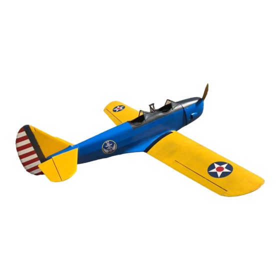
PT-19
• BUILDS QUICKLY
• REALISTIC FUN SCALE MODEL
WARRANTY
PT19P03 Printed in USA
Advertisement
Table of Contents

Subscribe to Our Youtube Channel
Related Manuals for Dynaflite PT-19


Summary of Contents for Dynaflite PT-19
- Page 1 AND USE OF THIS MODEL WARRANTY Dynaflite guarantees this kit to be free from defects in both material and workmanship at the date of purchase. This warranty does not cover any component parts damaged by use or modification. In no case shall Dynaflite's liability exceed the original cost of the purchased kit.
- Page 2 Build the Fuselage ..........8 Build the Wing .............12 Build theAilerons ............16 Your PT-19 is not a toy, but a sophisticated working Build the Stabilizer & Elevators ......17 model that functions like a full-size airplane. Because Build the Vertical Fin & Rudder ......19 of its performance, if you do not assemble and Mount the Wing to the Fuselage ......20...
- Page 3 These are the adhesives and supplies that you will need to build your Pt-19. We recommend Great Planes Pro™ CA and Epoxy Please inventory and inspect all parts carefully 4 oz.
- Page 4 IMPORTANT: During construction you will be using a number of balsa sticks to frame various assemblies. Ample material is included but you should study the plans, then make an effort to cut the longest pieces you will need first. Label the pieces as you cut them for later reference.
- Page 5 Never point the tip of a CA bottle toward your face and be especially careful when you unclog a CA tip. Hobbico CA Applicator Tips (HCAR3780) are highly recommended and will help keep the bottle from Fuse = Fuselage Stab = Horizontal Stabilizer Ply = Plywood clogging.
- Page 6 DIE PATTERNS...
- Page 7 DIE PATTERNS...
- Page 8 1. Place the fuselage drawing on your workbench and cover it with wax paper from bulkhead D aft. Begin construction by building the right rear side structure. 6. Place the right fuselage side over the plans and mark the locations of bulkheads B, C, D, E, F, and G on the side.
- Page 9 you made earlier. Before the glue cures, sight across 12. Glue bulkhead C to the fuselage sides with the top of both sides to double check the alignment. 6-minute epoxy. The bulkhead is slightly large so as not to bind on the sides. Use leftover 1/8" x 1/4" balsa sticks to reinforce the bulkhead/fuselage joint as shown in the photo.
- Page 10 needed, to get the center of each bulkhead to align properly. When you are satisfied that everything is aligned properly, glue the tail together. Also glue bulkhead F and G to the fuselage sides. 17. Glue the top ply part of bulkheads F and G into position.
- Page 11 cutting the sheeting to length as the leftover will be used in the next step. You will have to soak the sheeting with water to get it to bend properly. A small amount of ammonia or 50% alcohol added to the water will help to soften the wood fibers.
- Page 12 31. Glue the 1/4" x 1/2" x 42" balsa stringers 3. Pin the 1 /4" x 3/8" x 42" basswood lower to the fuselage sides. spar over the plan. Set the fuselage aside until later. It will be completed after the wing and stabilizer are built. 4.
- Page 13 LE even with the tops of the ribs. Use a long metal straightedge to get the LE as straight as possible. IMPORTANT: Use a straightedge along the sides of W1 and W11 to insure that they are straight and flat. 12.
- Page 14 23. Fit and glue the 1/8" die-cut ply webs to 16. Prepare the 1/4" x 3/4" LE that you the front of the landing gear rail using 30-minute installed in step 11 for sheeting. Carve and sand the epoxy. The webs should fit tightly between the ribs, LE to blend with the tops of the ribs.
- Page 15 27. After the glue has dried, turn the wing over and fit and glue a 3/32" x 15/16" x 24" sheet to the trailing edge between W5 and W11 with aliphatic resin. You will have to trim the 3/32" x 3" sheet installed in step 12.
- Page 16 39. Measure the distance under the left wing tip 35. Build the left wing panel. at the bottom of rib W11. If it is 8-3/4" you have exactly 6 degrees of dihedral in each panel. Don't be concerned if it is a little off as the dihedral angle is not at all critical.
- Page 17 12. Repeat steps 1 - 11 to build the left aileron. 2. Cut the lower TE sheet from a 3/32" x 3/4" x 24" balsa stick and pin it to the plan. 13. Cut six additional hinge blocks from the 1 /2" x 5/8"...
- Page 18 11. Cut the elevator tips from 5/8" x 15/16" x 6" balsa. Glue and pin them into position. 12. Glue and pin the shaped balsa elevator roots into position. 6. Cut and fit the ribs from 1/8" x 1/2" x 30" balsa.
- Page 19 3. Cut the fin post (trailing edge) from 3/8" x 15/16" x 30" balsa and pin it in position. 4. Cut the fin base from the 3/8" x 15/16" x 30" balsa and pin it into position. Glue all three pieces together.
- Page 20 12. Build three shims from leftover 3/32" and 1/16" balsa to create 5/32" thick shims. Place the shims into position over the plan and then glue and pin the TE into position. 13. Cut and fit the ribs from 3/16" x 1 /2" x 30" balsa.
- Page 21 12. Enlarge the wing bolt holes in only the wing with a 1/4" drill, drilling through the 1/16" ply plates as well. 8. Align the wing squarely on the fuselage. This is easily done using a piece of string as a guide. Put a pin in the tail of the fuselage on the centerline.
- Page 22 18. Sheet the bottom center of the wing. 25. Use leftover 1/8" ply to make a bulkhead where the leading edge of the wing meets the fuselage. First fit it to the bottom surface of the wing, 19. Attach a cap strip to the top and bottom of then use a pencil to draw the outline where it meets all the ribs using 3/32"...
- Page 23 2. Cut the stab mounts from 1/4" x 3/4" x 30 5. Cut two 10" pieces from a 3/8" x 3/4" x 24" balsa and glue them securely to the fuselage. balsa stick. These are the fairing blocks. Tack glue them into position on the shims and carve the assembly to shape.
- Page 24 Position the mount on the plans at the firewall then 8. Glue the fin and fin fairing blocks into position locate the engine on the mount to fit the front of the with 30-minute epoxy. Be sure the fin is cowl properly.
- Page 25 7. To drill the mounting holes in the cowl use the AFTER you have completely covered and finished cardboard technique again. Tape some cardboard your model, perform the following: to the fuselage side and mark the center of the mounting blocks. Slip the cowl into position and mark the location of the holes.
- Page 26 TEMPORARY PIN TO KEEP HINGE CENTERED You may cover and finish your model now if you desire. We prefer to install the radio before finishing so we don't add any hanger rash to our finished model. Our radio installation consisted of the following: C.
-
Page 27: Balance Your Propellers
We recommend the following control surface throws: PT-19 to achieve balance use Great Planes adhesive lead weights (GPMQ4485). An alternate to stick-on Elevator 1 -1 /8" up and down... - Page 28 sure the control surfaces respond correctly. The Get help from an experienced modeler when you engine must be "broken-in" according to the engine learn to operate engines. manufacturer's recommendations for break-in. Refer to the Engine Safety Precautions on the next page Use safety glasses when you operate model engines.
- Page 29 PT-19 up for the first time and make sure it performs correctly, then The full size PT-19 was a trainer for Army Air Corps give you valuable flight instruction. He can hand you Pilots. It was designed to teach takeoffs, landings, the transmitter when the PT-19 has climbed to a safe turns, stalls, spins and gentle aerobatics.
- Page 30 Here is a short list of terms and definitions so you'll Charge Jack -The plug receptacle of the switch know what they're talking about at the flying field. harness into which the charger is plugged to charge the airborne battery. An expanded scale voltmeter (ESV) can also be plugged into it to check battery Ailerons -Hinged control surfaces located on the voltage between flights.
- Page 31 Epoxy -A two-part resin/hardener glue that is Fuselage -The body of an airplane. extremely strong. It is generally available in 6 and 30-minute formulas. Used for critical points in the Glow Plug -The heat source for igniting the fuel/air aircraft where high strength is necessary. mixture in the engine.
- Page 32 NiCd -Nickel Cadmium battery. Rechargeable Slop -Unwanted, excessive free movement in a batteries which are typically used as power for radio control system. Often caused by a hole in a servo transmitters and receivers. arm or control horn that is too big for the pushrod wire or clevis pin.
Need help?
Do you have a question about the PT-19 and is the answer not in the manual?
Questions and answers