Table of Contents
Advertisement
Quick Links
Advertisement
Table of Contents

Related Manuals for ASROCK WRX80 CREATOR


Summary of Contents for ASROCK WRX80 CREATOR
- Page 2 (including damages for loss of profits, loss of business, loss of data, interruption of business and the like), even if ASRock has been advised of the possibility of such damages arising from any defect or error in the documentation or product.
- Page 3 If you require assistance please call ASRock Tel : +886-2-28965588 ext.123 (Standard International call charges apply) The terms HDMI®...
- Page 4 ES OF ANY KIND WHETHER UNDER THIS AGREEMENT OR OTHERWISE, EVEN IF INTEL HAS BEEN ADVISED OF THE POSSIBILITY OF SUCH DAMAGES. LICENSE TO USE COMMENTS AND SUGGESTIONS. This Agreement does NOT obligate Licensee to provide Intel with comments or suggestions regarding the Software. However, if Licensee provides Intel with comments or suggestions for the modification, correction, improvement or enhancement of (a) the Software or (b) Intel products or processes that work with the Software, Licensee grants to Intel a non-exclusive, worldwide,...
- Page 5 CE Warning This device complies with directive 2014/53/EU issued by the Commision of the European Community. This equipment complies with EU radiation exposure limits set forth for an uncontrolled environment. This equipment should be installed and operated with minimum distance 20cm between the radiator &...
-
Page 6: Table Of Contents
Contents Chapter 1 Introduction Package Contents Specifications Motherboard Layout I/O Panel 802.11ax Wi-Fi 6E Module and ASRock WiFi 2.4/5/6 GHz Antenna ASRock Thunderbolt™ 4 Module Chapter 2 Installation Installing the CPU Installing the CPU Cooler Installation of Memory Modules (DIMM) - Page 7 ASRock Motherboard Utility (A-Tuning) 3.2.1 Installing ASRock Motherboard Utility (A-Tuning) 3.2.2 Using ASRock Motherboard Utility (A-Tuning) ASRock Live Update & APP Shop 3.3.1 UI Overview 3.3.2 Apps 3.3.3 BIOS & Drivers 3.3.4 Setting ASRock Polychrome SYNC Chapter 4 UEFI SETUP UTILITY Introduction 4.1.1...
- Page 8 Tools Server Mgmt H/W Monitor Security Screen Boot Screen 4.10 Exit Screen...
-
Page 9: Chapter 1 Introduction
If you require technical support related to this mother- board, please visit our website for specific information about the model you are using. You may find the latest VGA cards and CPU support list on ASRock’s website as well. ASRock website http://www.asrock.com. -
Page 10: Specifications
• Supports AMD Socket sWRX8 for AMD Ryzen™ Threadripper™ PRO 5000WX and 3000WX Series Processors • Intersil Digital PWM • 8 Power Phase design • Supports ASRock Hyper BCLK Engine III • AMD WRX80 Chipset Memory • Eight Channel DDR4 Memory Technology • 8 x DDR4 DIMM Slots... - Page 11 WRX80 Creator Thunder- • Intel® JHL8540 Thunderbolt 4 Controller bolt • Supports Thunderbolt 4 interface with max. resolution of 5K (5120 x 2880) @ 60Hz for one display over a single cable connection • Supports Thunderbolt 4 interface with max. resolution of...
- Page 12 Wireless • 802.11ax Wi-Fi 6E Module • Supports IEEE 802.11a/b/g/n/ax • Supports Dual-Band 2x2 160MHz with extended 6GHz band* support * Wi-Fi 6E (6GHz band) will be supported by Microsoft® Windows® 11. The availability will depend on the different regulation status of each country and region. It will be activated (for supported countries) through Windows Update and software updates once available.
- Page 13 • 8 x SATA3 6.0 Gb/s Connectors • 1 x U.2 Connector * Supports NVMe SSD as boot disks * Supports ASRock U.2 Kit RAID • Supports RAID 0, RAID 1, RAID 5 and RAID 10 for SATA storage devices • Supports RAID 0, RAID 1 and RAID 5 for M.2 NVMe stor-...
- Page 14 • 3 x Chassis/Water Pump Fan Connectors (4-pin) (Smart Fan Speed Control) * The Chassis/Water Pump Fan supports the water cooler fan of maximum 2A (24W) fan power. * CPU_FAN2/WP, CHA_FAN1/WP, CHA_FAN2/WP and CHA_FAN3/WP can auto detect if 3-pin or 4-pin fan is in use. • 1 x 24 pin ATX Power Connector (Hi-Density Power Connector) * We recommend using a PSU with a max.
- Page 15 • ErP/EuP ready (ErP/EuP ready power supply is required) • CEC Tier II ready * For detailed product information, please visit our website: http://www.asrock.com Please realize that there is a certain risk involved with overclocking, including adjusting the setting in the BIOS, applying Untied Overclocking Technology, or using third-party overclocking tools.
-
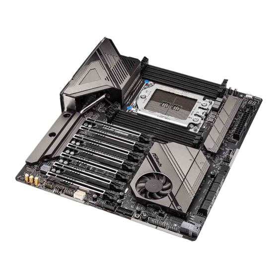
Page 16: Motherboard Layout
DDR4_E1 (64 bit, 288-pin module), White BIOS F_USB31_TC_1 DDR4_F1 (64 bit, 288-pin module), Blue DDR4_G1 (64 bit, 288-pin module), White M2_1 DDR4_H1 (64 bit, 288-pin module), Blue CHA_FAN2 PCIE1 WRX80 CREATOR PCIE2 M2_2 PCIE3 WRX80 PCIE4 ASPEED AST2500 PCIE5 PCIE6... - Page 17 WRX80 Creator No. Description VGA Header (VGA_CON1) 8 pin 12V Power Connector (ATX12V2) 8 pin 12V Power Connector (ATX12V1) 2 x 288-pin DDR4 DIMM Slots (DDR4_A1, DDR4_C1) 2 x 288-pin DDR4 DIMM Slots (DDR4_B1, DDR4_D1) CPU Fan Connector (CPU_FAN1) CPU / Waterpump Fan Connector (CPU_FAN2/WP)
- Page 18 No. Description Addressable LED Header (ADDR_LED1) Non Maskable Interrupt Button (NMI_BTN1) BMC SMBus Header (BMC_SMB1) Intelligent Platform Management Bus Header (IPMB1) COM Port Header (COM1) Right Angle Front Panel Audio Header (HD_AUDIO_RA1) Front Panel Audio Header (HD_AUDIO1)
-
Page 19: I/O Panel
WRX80 Creator 1.4 I/O Panel No. Description No. Description VGA Port 10G LAN RJ-45 Port (LAN1)** LAN RJ-45 Port (IPMI_LAN)* USB 3.2 Gen2 Ports (USB31_3_4) 10G LAN RJ-45 Port (LAN_2)** Mini DisplayPort Input Ports**** Central (Orange) USB 4.0 Thunderbolt 4 Type-C Ports... - Page 20 **There are two LEDs on each LAN port. Please refer to the table below for the LAN port LED indications. SPEED LED ACT/LINK LED SPEED LED ACT/LINK LED LAN Ports 10G LAN Port (LAN1, LAN_2) LED Indications Activity / Link LED Speed LED Status Description...
-
Page 21: Ax Wi-Fi 6E Module And Asrock Wifi 2.4/5/6 Ghz Antenna
WRX80 Creator 1.5 802.11ax Wi-Fi 6E Module and ASRock WiFi 2.4/5/6 GHz Antenna 802.11ax Wi-Fi 6E + BT Module This motherboard comes with an exclusive 802.11 a/b/g/n/ax Wi-Fi 6E + BT module (pre-installed on the rear I/O panel) that offers support for 802.11 a/b/g/n/ax Wi-Fi 6E connectivity standards and Bluetooth. -
Page 22: Asrock Thunderbolt™ 4 Module
• Size: 1.45-in x 1.65-in x 0.91-in, 3.7 cm x 4.2 cm x 2.3 cm Controller • Intel® JHL8540 Thunderbolt™ 4 Controller • Proprietary design for ASRock specific motherboard * Please note that plugging into other M.2 connector may damage the motherboard and this module • 2 x NGFF M Key Type M.2 Connectors... - Page 23 WRX80 Creator • PCI Express 3.0 x4 interface Interface • Supports Thunderbolt 4 interface with max. resolution of 5K (5120 x 2880) @ 60Hz for one display over a single cable connection Graphics • Supports Thunderbolt 4 interface with max. resolution of...
- Page 24 Step 2 Connect one end of the Mini DisplayPort to DisplayPort Adapter Cable to the Mini DisplayPort Input Port (A) on ASRock Thunderbolt 4 Module on I/O panel. Then connect the other end of the cable to the DisplayPort Output Port (B) on the...
- Page 25 2. Please choose regular Mini DisplayPort to DisplayPort Adapter Cables instead of right angled ones when you use two Mini DisplayPort Input Ports simultaneously. Step 4 Connect the Thunderbolt cable(s) from your Thunderbolt-enabled device(s) to the USB 4.0 Thunderbolt 4 Type-C Port(s) on ASRock Thunderbolt 4 Module on I/ O panel.
-
Page 26: Chapter 2 Installation
Chapter 2 Installation This is an EATX form factor motherboard. Before you install the motherboard, study the configuration of your chassis to ensure that the motherboard fits into it. Pre-installation Precautions Take note of the following precautions before you install motherboard components or change any motherboard settings. -
Page 27: Installing The Cpu
WRX80 Creator 2.1 Installing the CPU Unplug all power cables before installing the CPU. - Page 29 WRX80 Creator Carr ier Frame with CPU Rail Frame Please make sure that the carrier frame with CPU is closely attached to the rail frame while inserting it. Install the orange carrier frame with CPU. Don’t separate them.
-
Page 31: Installing The Cpu Cooler
WRX80 Creator 2.2 Installing the CPU Cooler After you install the CPU into this motherboard, it is necessary to install a larger heatsink and cooling fan to dissipate heat. You also need to spray thermal grease between the CPU and the heatsink to improve heat dissipation. Make sure that the CPU and the heatsink are securely fastened and in good contact with each other. -
Page 33: Installation Of Memory Modules (Dimm)
WRX80 Creator 2.3 Installation of Memory Modules (DIMM) This motherboard provides eight 288-pin DDR4 (Double Data Rate 4) DIMM slots and supports Eight Channel Memory Technology. 1. It is not allowed to install a DDR, DDR2 or DDR3 memory module into a DDR4 slot;... - Page 34 The DIMM only fits in one correct orientation. It will cause permanent damage to the motherboard and the DIMM if you force the DIMM into the slot at incorrect orientation.
-
Page 35: Expansion Slots (Pcie Slots)
WRX80 Creator 2.4 Expansion Slots (PCIe Slots) There are 7 PCIe slots on this motherboard. Before installing an expansion card, please make sure that the power supply is switched off or the power cord is unplugged. Please read the documentation of the expansion card and make necessary hardware settings for the card before you start the installation. -
Page 36: Jumpers Setup
2.5 Jumpers Setup The illustration shows how jumpers are setup. When the jumper cap is placed on the pins, the jumper is “Short”. If no jumper cap is placed on the pins, the jumper is “Open”. Clear CMOS Jumper Short: Clear CMOS (CLRCMOS1) Open: Default 2-pin Jumper... -
Page 37: Onboard Headers And Connectors
WRX80 Creator 2.6 Onboard Headers and Connectors Onboard headers and connectors are NOT jumpers. Do NOT place jumper caps over these headers and connectors. Placing jumper caps over the headers and connectors will cause permanent damage to the motherboard. System Panel Header... - Page 38 Auxiliary Panel Header This header supports multiple (18-pin AUX_PANEL1) functions on the front panel, (see p.8, No. 28) including the front panel SMB, internet status indicator and chassis intrusion pin. A. Front panel SMBus connecting pin (6-1 pin FPSMB) This header allows you to connect SMBus (System Management Bus) equipment. It can be used for communication between peripheral equipment in the system, which has slower transmission rates, and power management equipment.
- Page 39 WRX80 Creator Serial ATA3 Connectors These eight SATA3 Right Angle: connectors support SATA (SATA3_1: data cables for internal see p.8, No. 22)(Lower) storage devices with up to (SATA3_2: 6.0 Gb/s data transfer rate. see p.8, No. 22)(Upper) (SATA3_3: see p.8, No. 21)(Lower) (SATA3_4: see p.8, No.
- Page 40 Right Angle: Dummy IntA_PA_D+ (19-pin USB3_5_6) IntA_PB_D+ IntA_PA_D- IntA_PB_D- (see p.8, No. 18) IntA_PA_SSTX+ IntA_PB_SSTX+ IntA_PA_SSTX- IntA_PB_SSTX- IntA_PA_SSRX+ IntA_PB_SSRX+ IntA_PA_SSRX- IntA_PB_SSRX- Vbus Vbus Front Panel Type C USB There is one Front 3.2 Gen2 Header Panel Type C USB 3.2 (26-pin F_USB31_TC_1) Gen2 Header on this (see p.8, No.
- Page 41 WRX80 Creator Chassis Water Pump Fan This motherboard Connectors provides three 4-Pin water FAN_SPEED_CONTROL (4-pin CHA_FAN1/WP) cooling chassis fan CPU_FAN_SPEED FAN_VOLTAGE (see p.8, No. 33) connectors. If you plan to connect a 3-Pin chassis water cooler fan, please connect it to Pin 1-3.
- Page 42 ATX Power Connector This motherboard (24-pin ATXPWR1) provides a 24-pin ATX (see p.8, No. 12) power connector. *We recommend using a PSU with a max. current of 3A on +5VSB. ATX 12V Power This motherboard Connectors provides two 8-pin ATX (8-pin ATX12V1) 12V power connectors.
- Page 43 WRX80 Creator SPI_DQ3 SPI TPM Header This connector supports SPI SPI_PWR Dummy (13-pin TPM_BIOS_PH1) Trusted Platform Module (TPM) SPI_MOSI RST# (see p.8, No. 13) system, which can securely store TPM_PIRQ keys, digital certificates, pass- words, and data. A TPM system...
- Page 44 Non Maskable Interrupt Please connect a NMI device to Button Header this header. (NMI_BTN) CONTROL (see p.8, No. 35) RGB LED Header This RGB header is used to (4-pin RGB_LED1) connect RGB LED extension +12V G R (see p.8, No. 8) cable which allow users to choose from various LED lighting effects.
-
Page 45: Smart Switches
WRX80 Creator 2.7 Smart Switches The motherboard has three smart switches: Power Button, Reset Button and Clear CMOS Button, allowing users to quickly turn on/off the system, reset the system, clear the CMOS values or flash the BIOS. Power Button... -
Page 46: Dr. Debug
2.8 Dr. Debug Dr. Debug is used to provide code information, which makes troubleshooting even easier. Please see the diagrams below for reading the Dr. Debug codes. Code Description 0x10 PEI_CORE_STARTED 0x11 PEI_CAR_CPU_INIT 0x15 PEI_CAR_NB_INIT 0x19 PEI_CAR_SB_INIT 0x31 PEI_MEMORY_INSTALLED 0x32 PEI_CPU_INIT 0x33 PEI_CPU_CACHE_INIT... - Page 47 WRX80 Creator 0x63 DXE_CPU_INIT 0x68 DXE_NB_HB_INIT 0x69 DXE_NB_INIT 0x6A DXE_NB_SMM_INIT 0x70 DXE_SB_INIT 0x71 DXE_SB_SMM_INIT 0x72 DXE_SB_DEVICES_INIT 0x78 DXE_ACPI_INIT 0x79 DXE_CSM_INIT 0x90 DXE_BDS_STARTED 0x91 DXE_BDS_CONNECT_DRIVERS 0x92 DXE_PCI_BUS_BEGIN 0x93 DXE_PCI_BUS_HPC_INIT 0x94 DXE_PCI_BUS_ENUM 0x95 DXE_PCI_BUS_REQUEST_RESOURCES 0x96 DXE_PCI_BUS_ASSIGN_RESOURCES 0x97 DXE_CON_OUT_CONNECT 0x98 DXE_CON_IN_CONNECT...
- Page 48 0x99 DXE_SIO_INIT 0x9A DXE_USB_BEGIN 0x9B DXE_USB_RESET 0x9C DXE_USB_DETECT 0x9D DXE_USB_ENABLE 0xA0 DXE_IDE_BEGIN 0xA1 DXE_IDE_RESET 0xA2 DXE_IDE_DETECT 0xA3 DXE_IDE_ENABLE 0xA4 DXE_SCSI_BEGIN 0xA5 DXE_SCSI_RESET 0xA6 DXE_SCSI_DETECT 0xA7 DXE_SCSI_ENABLE 0xA8 DXE_SETUP_VERIFYING_PASSWORD 0xA9 DXE_SETUP_START 0xAB DXE_SETUP_INPUT_WAIT 0xAD DXE_READY_TO_BOOT 0xAE DXE_LEGACY_BOOT...
- Page 49 WRX80 Creator 0xAF DXE_EXIT_BOOT_SERVICES 0xB0 RT_SET_VIRTUAL_ADDRESS_MAP_BEGIN 0xB1 RT_SET_VIRTUAL_ADDRESS_MAP_END 0xB2 DXE_LEGACY_OPROM_INIT 0xB3 DXE_RESET_SYSTEM 0xB4 DXE_USB_HOTPLUG 0xB5 DXE_PCI_BUS_HOTPLUG 0xB6 DXE_NVRAM_CLEANUP 0xB7 DXE_CONFIGURATION_RESET 0xF0 PEI_RECOVERY_AUTO 0xF1 PEI_RECOVERY_USER 0xF2 PEI_RECOVERY_STARTED 0xF3 PEI_RECOVERY_CAPSULE_FOUND 0xF4 PEI_RECOVERY_CAPSULE_LOADED 0xE0 PEI_S3_STARTED 0xE1 PEI_S3_BOOT_SCRIPT 0xE2 PEI_S3_VIDEO_REPOST...
- Page 50 0xE3 PEI_S3_OS_WAKE 0x50 PEI_MEMORY_INVALID_TYPE 0x53 PEI_MEMORY_NOT_DETECTED 0x55 PEI_MEMORY_NOT_INSTALLED 0x57 PEI_CPU_MISMATCH 0x58 PEI_CPU_SELF_TEST_FAILED 0x59 PEI_CPU_NO_MICROCODE 0x5A PEI_CPU_ERROR 0x5B PEI_RESET_NOT_AVAILABLE 0xD0 DXE_CPU_ERROR 0xD1 DXE_NB_ERROR 0xD2 DXE_SB_ERROR 0xD3 DXE_ARCH_PROTOCOL_NOT_AVAILABLE 0xD4 DXE_PCI_BUS_OUT_OF_RESOURCES 0xD5 DXE_LEGACY_OPROM_NO_SPACE 0xD6 DXE_NO_CON_OUT 0xD7 DXE_NO_CON_IN...
- Page 51 WRX80 Creator 0xD8 DXE_INVALID_PASSWORD 0xD9 DXE_BOOT_OPTION_LOAD_ERROR 0xDA DXE_BOOT_OPTION_FAILED 0xDB DXE_FLASH_UPDATE_FAILED 0xDC DXE_RESET_NOT_AVAILABLE 0xE8 PEI_MEMORY_S3_RESUME_FAILED 0xE9 PEI_S3_RESUME_PPI_NOT_FOUND 0xEA PEI_S3_BOOT_SCRIPT_ERROR 0xEB PEI_S3_OS_WAKE_ERROR...
-
Page 52: M.2_Ssd (Ngff) Module Installation Guide (M2_1)
2.9 M.2_SSD (NGFF) Module Installation Guide (M2_1) The M.2, also known as the Next Generation Form Factor (NGFF), is a small size and versatile card edge connector that aims to replace mPCIe and mSATA. The Hyper M.2 Socket (M2_1, Key M) supports type 2260/2280/22110 SATA3 6.0 Gb/s & PCIe Gen4x4 (64 Gb/s) modes. - Page 53 WRX80 Creator Step 3 Before installing a M.2 (NGFF) SSD module, please loosen the screws to remove the M.2 heatsink. *Please remove the protective films on the bottom side of the M.2 heatsink before you install a M.2 SSD module.
- Page 54 Step 6 Tighten the screw with a screwdriver to secure the M.2 heatsink into place. Please do not overtighten the screw as this might damage the module and M.2 heatsink.
- Page 55 WRX80 Creator M.2_SSD (NGFF) Module Support List Vendor Interface SanDisk PCIe SanDisk-SD6PP4M-128G( Gen2 x2) Intel PCIe INTEL 6000P-SSDPEKKF256G7 (nvme) Intel PCIe INTEL 6000P-SSDPEKKF512G7 (nvme) Intel PCIe SSDPEKKF512G7 NVME / 512GB Intel SATA 540S-SSDSCKKW240H6 / 240GB Kingston PCIe Kingston SHPM2280P2 / 240G (Gen2 x4)
-
Page 56: M.2_Ssd (Ngff) Module Installation Guide (M2_2)
2.10 M.2_SSD (NGFF) Module Installation Guide (M2_2) The M.2, also known as the Next Generation Form Factor (NGFF), is a small size and versatile card edge connector that aims to replace mPCIe and mSATA. The Hyper M.2 Socket (M2_2, Key M), supports type 2260/2280 PCIe Gen4x4 (64 Gb/s) mode. Installing the M.2_SSD (NGFF) Module Step 1 This motherboard supports M.2_SSD... - Page 57 WRX80 Creator Step 3 Before installing a M.2 (NGFF) SSD module, please loosen the screws to remove the M.2 heatsink. *Please remove the protective films on the bottom side of the M.2 heatsink before you install a M.2 SSD module.
- Page 58 Step 6 Tighten the screw with a screwdriver to secure the M.2 heatsink into place. Please do not overtighten the screw as this might damage the module and M.2 heatsink.
- Page 59 WRX80 Creator M.2_SSD (NGFF) Module Support List Vendor Interface SanDisk PCIe SanDisk-SD6PP4M-128G( Gen2 x2) Intel PCIe INTEL 6000P-SSDPEKKF256G7 (nvme) Intel PCIe INTEL 6000P-SSDPEKKF512G7 (nvme) Intel PCIe SSDPEKKF512G7 NVME / 512GB Kingston PCIe Kingston SHPM2280P2 / 240G (Gen2 x4) Samsung PCIe...
-
Page 60: Chapter 3 Software And Utilities Operation
Chapter 3 Software and Utilities Operation 3.1 Installing Drivers The Support CD that comes with the motherboard contains necessary drivers and useful utilities that enhance the motherboard’s features. Running The Support CD To begin using the support CD, insert the CD into your CD-ROM drive. The CD automatically displays the Main Menu if “AUTORUN”... -
Page 61: Asrock Motherboard Utility (A-Tuning)
3.2.1 Installing ASRock Motherboard Utility (A-Tuning) ASRock Motherboard Utility (A-Tuning) can be downloaded from ASRock Live Update & APP Shop. After the installation, you will find the icon “ASRock Mother- board Utility (A-Tuning)“ on your desktop. Double-click the “ASRock Motherboard Utility (A-Tuning)“... - Page 62 OC Tweaker Configurations for overclocking the system. System Info View information about the system. *The System Browser tab may not appear for certain models.
- Page 63 Settings Configure ASRock ASRock Motherboard Utility (A-Tuning). Click to select "Auto run at Windows Startup" if you want ASRock Motherboard Utility (A-Tuning) to be launched when you start up the Windows operating system.
-
Page 64: Asrock Live Update & App Shop
Double-click on your desktop to access ASRock Live Update & APP Shop utility. *You need to be connected to the Internet to download apps from the ASRock Live Update & APP Shop. 3.3.1 UI Overview Category Panel Hot News... -
Page 65: Apps
WRX80 Creator 3.3.2 Apps When the "Apps" tab is selected, you will see all the available apps on screen for you to download. Installing an App Step 1 Find the app you want to install. The most recommended app appears on the left side of the screen. The other various apps are shown on the right. - Page 66 Step 3 If you want to install the app, click on the red icon to start downloading. Step 4 When installation completes, you can find the green "Installed" icon appears on the upper right corner. To uninstall it, simply click on the trash can icon *The trash icon may not appear for certain apps.
- Page 67 WRX80 Creator Upgrading an App You can only upgrade the apps you have already installed. When there is an available new version for your app, you will find the mark of "New Version" appears below the installed app icon. Step 1 Click on the app icon to see more details.
-
Page 68: Bios & Drivers
3.3.3 BIOS & Drivers Installing BIOS or Drivers When the "BIOS & Drivers" tab is selected, you will see a list of recommended or critical updates for the BIOS or drivers. Please update them all soon. Step 1 Please check the item information before update. Click on to see more details. -
Page 69: Setting
WRX80 Creator 3.3.4 Setting In the "Setting" page, you can change the language, select the server location, and determine if you want to automatically run the ASRock Live Update & APP Shop on Windows startup. -
Page 70: Asrock Polychrome Sync
3.4 ASRock Polychrome SYNC ASRock Polychrome SYNC is a lighting control utility specifically designed for unique indi- viduals with sophisticated tastes to build their own stylish colorful lighting system. Simply by connecting the LED strip, you can customize various lighting schemes and patterns, including Static, Breathing, Strobe, Cycling, Music, Wave and more. - Page 71 WRX80 Creator Connecting the Addressable RGB LED Strip Connect your Addressable RGB LED strip to the Addressable LED Headers (ADDR_LED1, ADDR_LED2) on the motherboard. ADDR_LED2 DO_ADDR VOUT ADDR_LED1 WRX80 CREATOR DO_ADDR VOUT 1. Never install the RGB LED cable in the wrong orientation; otherwise, the cable may be damaged.
- Page 72 ASRock Polychrome SYNC Utility Now you can adjust the RGB LED color through the ASRock Polychrome SYNC Utility. Download this utility from the ASRock Live Update & APP Shop and start coloring your PC style your way! Drag the tab to customize your preference.
-
Page 73: Chapter 4 Uefi Setup Utility
WRX80 Creator Chapter 4 UEFI SETUP UTILITY 4.1 Introduction This section explains how to use the UEFI SETUP UTILITY to configure your system. You may run the UEFI SETUP UTILITY by pressing <F2> or <Del> right after you power on the computer, otherwise, the Power-On-Self-Test (POST) will continue with its test routines. -
Page 74: Navigation Keys
4.1.2 Navigation Keys Use < > key or < > key to choose among the selections on the menu bar, and use < > key or < > key to move the cursor up or down to select items, then press <Enter>... -
Page 75: Main Screen
WRX80 Creator 4.2 Main Screen When you enter the UEFI SETUP UTILITY, the Main screen will appear and display the system overview. -
Page 76: Oc Tweaker Screen
4.3 OC Tweaker Screen In the OC Tweaker screen, you can set up overclocking features. Because the UEFI software is constantly being updated, the following UEFI setup screens and descriptions are for reference purpose only, and they may not exactly match what you see on your screen. - Page 77 WRX80 Creator Bixby Spread Spectrum Enable Bixby Spread Spectrum to reduce electromagnetic interference for passing EMI tests. Disable to achieve higher clock speeds when overclocking. FCH Spread Spectrum Enable FCH Spread Spectrum to reduce electromagnetic interference for passing EMI tests. Disable to achieve higher clock speeds when overclocking.
- Page 78 DRAM Timing Configuration Voltage Configuration Voltage Mode [OC] If this option is selected, there is larger range voltage for overclocking. [Stable] If this option is selected, there is smaller range voltage for stable system. CPU Vcore Voltage Configure the voltage for the CPU Vcore. CPU Vcore Load-Line Calibration CPU Load-Line Calibration helps prevent CPU voltage droop when the system is under heavy loading.
- Page 79 WRX80 Creator VPPM_ABCD Configure the voltage for the VPPM_ABCD. VPPM_EFGH Configure the voltage for the VPPM_EFGH. VDDCR_SOC_S5 Configure the voltage for the VDDCR_SOC_S5. CPU VDD +1.8 V Configure the voltage for the CPU VDD 1.8 PROM. +1.8VSB Voltage Configure the voltage for the +1.8VSB.
-
Page 80: Advanced Screen
4.4 Advanced Screen In this section, you may set the configurations for the following items: CPU Configuration, Onboard Devices Configuration, Storage Configuration, ACPI Configuration, Super IO Configuration, Serial Port Console Redirection, Trusted Computing and AMD Mem Configuration. Setting wrong values in this section may cause the system to malfunction. UEFI Configuration Active Page on Entry Select the default page when entering the UEFI setup utility. -
Page 81: Cpu Configuration
WRX80 Creator 4.4.1 CPU Configuration SVM Mode When this is set to [Enabled], a VMM (Virtual Machine Architecture)can utilize the additional hardware capabilities provided by AMD-V. The default value is [Enabled]. Coniguration options: [Enabled] and [Disabled]. SMT Mode This item can be used to disable symmetric multithreading. -
Page 82: Onboard Devices Configuration
4.4.2 Onboard Devices Configuration Primary Graphics Adapter Select a primary VGA. *To ensure better graphics compatibility, the default is set to [Onboard] (boot from onboard VGA). Onboard VGA Enable/disable the Onboard VGA. SR-IOV Support Enable/disable the SR-IOV (Single Root IO Virtualization Support) if the system has SR-IOV capable PCIe devices. - Page 83 WRX80 Creator WAN Radio Configure the WiFi module's connectivity. BT On/Off Enable/disable the bluetooth. Power Button LED Enable/disable the Power Button LED.
-
Page 84: Storage Configuration
4.4.3 Storage Configuration SATA Controller(s) Enable/disable the SATA controllers. SATA Mode AHCI: Supports new features that improve performance. RAID: Combine multiple disk drives into a logical unit. -
Page 85: Acpi Configuration
WRX80 Creator 4.4.4 ACPI Configuration Suspend to RAM It is recommended to select auto for ACPI S3 power saving. Deep Sleep Configure deep sleep mode for power saving when the computer is shut down. -
Page 86: Super Io Configuration
4.4.5 Super IO Configuration Serial Port 1 Configuration Enable or disable the Serial port 1. -
Page 87: Serial Port Console Redirection
WRX80 Creator 4.4.6 Serial Port Console Redirection COM0 Console Redirection Use this option to enable or disable Console Redirection. If this item is set to Enabled, you can select a COM Port to be used for Console Redirection. Console Redirection Settings Use this option to configure Console Redirection Settings, and specify how your computer and the host computer to which you are connected exchange information. - Page 88 transmission speed. The options include [9600], [19200], [38400], [57600] and [115200]. Data Bits Use this item to set the data transmission size. The options include [7] and [8] (Bits). Parity Use this item to select the parity bit. The options include [None], [Even], [Odd], [Mark] and [Space].
- Page 89 WRX80 Creator Serial Port for Out-of-Band Management/Windows Emergency Management Services (EMS) Console Redirection Use this option to enable or disable Console Redirection. If this item is set to Enabled, you can select a COM Port to be used for Console Redirection.
-
Page 90: Trusted Computing
4.4.7 Trusted Computing NOTE: Options vary depending on the version of your connected TPM module. Security Device Support Use this item to enable or disable BIOS support for security device. O.S. will not show Security Device. TCG EFI protocol and INT1A interface will not be available. Active PCR banks This item displays active PCR Banks. - Page 91 WRX80 Creator Platform Hierarchy Use this item to enable or disable Platform Hierarchy. Storage Hierarchy Use this item to enable or disable Storage Hierarchy. Endorsement Hierarchy Use this item to enable or disable Endorsement Hierarchy. Physical Presence Spec version Select this item to tell OS to support PPI spec version 1.2 or 1.3. Please note that some HCK tests might not support version 1.3.
-
Page 92: Amd Mem Configuration
4.4.8 AMD Mem Configuration To display memory configuration (initialized by ABL) status. - Page 93 WRX80 Creator 4.5 Tools NVME Sanitization Tool After you sanitize SSD, all user data will be permantly destroyed on the SSD and cannot be recovered. Instant Flash Save UEFI files in your USB storage device and run Instant Flash to update your...
- Page 94 4.6 Server Mgmt BMC Support Use this item to enable or disable interfaces to communicate with BMC. IPMI Interface Type Use this item to select IPMI Interface Type. Wait For BMC Wait For BMC response for specified time out. BMC starts at the same time when BIOS starts during AC power ON.
- Page 95 WRX80 Creator 4.6.1 BMC Network Configuration BMC Out of Band Access Use this item to enable or disable BMC Out of band Access. Manual Setting IPMI LAN If [No] is selected, the IP address is assigned by DHCP. If you prefer using a static IP address, toggle to [Yes], and the changes take effect after the system reboots.
- Page 96 The default login information for the IPMI web interface is: Username: admin Password: admin For more instructions on how to set up remote control environment and use the IPMI man- agement platform, please refer to the IPMI Configuration User Guide or go to the Support website at: http://www.asrockrack.com/support/faq.asp VLAN Enabled/Disabled Virtual Local Area Network.
- Page 97 WRX80 Creator 4.6.2 System Event Log SEL Components Change this to enable ro disable event logging for error/progress codes during boot. Erase SEL Use this to choose options for earsing SEL. When SEL is Full Use this to choose options for reactions to a full SEL.
- Page 98 4.6.3 BMC Tools Load BMC Default Settings Use this item to Load BMC Default Settings KCS Control Select this KCS interface state after POST end. If [Enabled] us selected, the BMC will remain KCS interface after POST stage. If [Disabled] is selected, the BMC will disable KCS interface after POST stage...
- Page 99 WRX80 Creator 4.7 H/W Monitor In this section, it allows you to monitor the status of the hardware on your system, includ- ing the parameters of the CPU temperature, motherboard temperature, CPU fan speed, chassis fan speed, and the critical voltage.
- Page 100 CHA_FAN2/WP Select a fan mode for CHA_FAN2/WP. Fan4 Control Mode If [Auto] is selected, the fan speed will controlled by BMC. CHA_FAN3/WP Select a fan mode for CHA_FAN3/WP. Fan5 Control Mode If [Auto] is selected, the fan speed will controlled by BMC. SB_FAN1 Setting Select a fan mode for SB_FAN1.
- Page 101 WRX80 Creator 4.8 Security Screen In this section you may set or change the supervisor/user password for the system. You may also clear the user password. Supervisor Password Set or change the password for the administrator account. Only the administrator has authority to change the settings in the UEFI Setup Utility.
- Page 102 4.9 Boot Screen This section displays the available devices on your system for you to configure the boot settings and the boot priority. Boot From Onboard LAN Allow the system to be waked up by the onboard LAN. Setup Prompt Timeout Configure the number of seconds to wait for the setup hot key.
- Page 103 WRX80 Creator 4.10 Exit Screen Save Changes and Exit When you select this option the following message, “Save configuration changes and exit setup?” will pop out. Select [OK] to save changes and exit the UEFI SETUP UTILITY. Discard Changes and Exit When you select this option the following message, “Discard changes and exit...
- Page 104 Contact Information If you need to contact ASRock or want to know more about ASRock, you’re welcome to visit ASRock’s website at http://www.asrock.com; or you may contact your dealer for further information. For technical questions, please submit a support request form at https://event.asrock.com/tsd.asp...
- Page 105 13848 Magnolia Ave, Chino, CA91710 Phone/Fax No: +1-909-590-8308/+1-909-590-1026 hereby declares that the product Product Name : Motherboard WRX80 Creator Model Number : Conforms to the following speci cations: FCC Part 15, Subpart B, Unintentional Radiators Supplementary Information: is device complies with part 15 of the FCC Rules. Operation is subject to the...
- Page 106 EU Declaration of Conformity For the following equipment: Motherboard (Product Name) WRX80 Creator / ASRock (Model Designation / Trade Name) ASRock Incorporation (Manufacturer Name) 2F., No.37, Sec. 2, Jhongyang S. Rd., Beitou District, Taipei City 112, Taiwan (Manufacturer Address) Radio Equipment Directive - 2014/53/EU Article 3.1(b)
- Page 107 EU Declaration of Conformity Product: Product Motherboard Model / Brand / SN. WRX80 Creator / ASRock Authorized Representative (UK-GB): Name: Gary Tsui Address: Bijsterhuizen 11-11, 6546 AR Nijmegen,The Netherlands Contact person: Gary Tsui This declaration is issued under the sole responsibility of the mentioned Manufacturer.
Need help?
Do you have a question about the WRX80 CREATOR and is the answer not in the manual?
Questions and answers