Table of Contents
Advertisement
Advertisement
Table of Contents

Related Manuals for Aruba AP 70


Summary of Contents for Aruba AP 70
-
Page 1: Access Point
Aruba AP 70 Access Point Installation Guide... - Page 2 Cisco or Nortel VPN client devices constitutes complete acceptance of liability by that individual or corporation for this action and indemnifies, in full, Aruba Wireless Networks, Inc. from any and all legal actions that might be taken against it with respect to infringement of copyright on behalf of Cisco Systems or Nortel Networks.
-
Page 3: Table Of Contents
....... Setting Aruba AP 70 Parameters AP Deployment......... - Page 4 ........Aruba AP 70 Access Point .
-
Page 5: Chapter 1 Introduction
IEEE 802.11a or IEEE 802.11b/g wireless adapters) and the wired LAN. As a wireless Air Monitor (AM), a feature unique to Aruba products, the Aruba AP 70 enhances wireless networks by collecting statistics, monitoring traffic, detecting intrusions, enforcing security policies, balancing wireless traffic load, self-healing coverage gaps, and more. -
Page 6: Front View
Introduction Chapter 1 Front View Aruba AP 70 Front View IGURE Aruba AP 70 0500159 Installation Guide November 2005... - Page 7 ENET1 LED on Aruba AP 70 rev D and earlier models configured for 10Base-T traffic does not illuminate, but traffic is processed normally. The ENET1 LED on Aruba AP 70 rev E and later models (circa March, 2005 and lat- er) illuminates when configured for 10Base-T traffic.
- Page 8 RFID tracking or spectrum analysis. DC Power Socket This socket is used to connect the optional AC power adapter (not included). If POE is being used to supply power to the Aruba AP 70, the power adapter is not necessary. B/G Antenna Jack Not used.
-
Page 9: Back View
Introduction Chapter 1 Back View Aruba AP 70 Back View IGURE Aruba AP 70 Installation Guide... -
Page 10: The Aruba Ap Setup Process
Fold-Out Internal Antenna This fold-out antenna allows the Aruba AP 70 to be used upright on a table, shelf, ceiling, or wall. If you are configuring external antennas, the internal antenna can be left closed. -
Page 11: Chapter 2 Provisioning Access Points
Access Points must comply with local broadcast regulations. Specifically, Access Points must use channel assignment appropriate to the location in which the Access Point will be used. Aruba Networks, in compliance with governmental requirements, has designed the Aruba AP 70 such that only authorized network administrators can change these settings. -
Page 12: Aruba Discovery Protocol
ADP packets to the Aruba Mobility Controller. Once these discovery prerequisites are met, the Mobility Controller will respond to APs with the IP address of the Master Aruba switch. The APs can then obtain their image and configuration. To enable ADP on an Aruba Mobility Controller, enter:... -
Page 13: Ap Reprovisioning
This is the subnet from which the AP gets an IP during provisioning. (This is not the IP address the AP will use when deployed. Also, the provisioning subnet should be not be the same as an existing subnet on the Mobility Controller.) Aruba AP 70 Installation Guide... - Page 14 Enable Enter the required information and click .The Port Range screen displays. Port Range Screen IGURE Specify the Aruba AP 70-specific parameters. Complete the IPSec (optional), Master Discovery, and IP Settings and click Apply Aruba AP 70 0500159 Installation Guide...
- Page 15 State will have changed to P (Provisioned). Check that the configured parameters are reflected in the AP list entry. Aruba Networks recommends that you provision each AP for a unique location as suggested by site-survey planning. Label each AP with this location information and place the AP in its proper location.
-
Page 16: Manual Provisioning
4- or 8-conductor, Category 5 UTP , straight-through FE cable. 1. IEEE 802.3af-complaint devices like the Aruba AP 70 use the same wire pairs for data versus for power. Within the 802.3af standard, there are two sub-specifications on how wire pairs are assigned. -
Page 17: Connecting The Console Terminal
Manual provisioning requires this procedure. You must use the serial console breakout adapter cable to be able to access the serial console interface to the Aruba AP 70 while allowing the device to be powered by the AC adapter or POE (from an Aruba Mobility Controller). - Page 18 Provisioning Access Points Chapter 2 Connect the adapter’s “To AP” RJ-45 connector to the Aruba AP 70 FE Port. Connect the adapter’s DB-9 connector to the serial port on the console terminal. Connect the adapter’s “To Network” RJ-45 connector to the LAN.
- Page 19 Press <Enter> a few times to establish communication between the Aruba AP 70 and terminal. From the Aruba AP 70 console, access the apboot prompt. Depending on the Aruba AP 70 status, you will see one of the following on your terminal: Autoboot countdown—The countdown prompt allows you to interrupt the normal startup process and access the apboot prompt where provisioning is performed.
-
Page 20: Setting Aruba Ap 70 Parameters
Provisioning Access Points Chapter 2 TFTP time out—If the Aruba AP 70 cannot locate an Aruba Mobility Controller on its network port, the following type of output is repeatedly displayed: Loading FLASH image... Verifying checksum... passed BOOTP broadcast 1 DHCP IP address: 10.1.2.250... - Page 21 Otherwise, configure the AP with a static IP address using the following commands: apboot> setenv ipaddr <static IP address for the AP> apboot> setenv netmask <static IP address mask> apboot> setenv gatewayip <default gateway IP address> Aruba AP 70 Installation Guide...
- Page 22 Within any floor, a unique number (1-65534) is required for each access point or air monitor. If you performed the recommended site survey using the Aruba RF Plan tool, the location data for all access points and air monitors can be found on the tool’s deployment page (see the Aruba RF Plan User’s Guide).
- Page 23 Use the same fixed point and orientation for all floors in a building. Save the configuration and reboot the Aruba AP 70. apboot> save apboot> boot Once the Aruba AP 70 boots, disconnect it and mount it in its intended service location. Aruba AP 70 Installation Guide...
- Page 24 Provisioning Access Points Chapter 2 Aruba AP 70 0500159 Installation Guide November 2005...
-
Page 25: Chapter 3 Ap Deployment
This chapter explains how to mount and connect the Aruba AP 70. Mounting the Aruba AP 70 When provisioning is complete, mount the Aruba AP 70 at its intended service location. The Aruba AP 70 Access Points are intended only for installation in Environment A as defined in IEEE 802.3.af. -
Page 26: Free-Standing Placement
AP Deployment Chapter 3 The Aruba AP 70 can be mounted on a wall or suspended from above (not shown) using one of the optional mounting kits (dimensions vary) in the following ways: Aruba AP 70 Mounting Options IGURE For dimensions, see Appendix C, “Product... -
Page 27: Using The Built-In Mounting Slots
Chapter 3 Using the Built-In Mounting Slots The keyhole-shaped slots on the back of the Aruba AP 70 can be used to attach the device upright to an indoor wall or shelf. Do not use the mounting slots to hang the Aruba AP 70... -
Page 28: Using The Optional Mounting Kits
25). Using the Optional Mounting Kits Use the optional mounting kit to attach the Aruba AP 70 to a wall, shelf, or ceiling. For installation, see the Aruba AP 70 Mounting Kit Installation Notes (P/N 0500037-01) provided with each kit. -
Page 29: Connecting Required Cables
The maximum length for FE cables is 100 meters (325 feet). When the Aruba AP 70 is installed in an air-handling space, such as above suspended ceilings, as described in National Electrical Code (2002) Article 300.22(C), and Canadian Electrical Code, Sections 2-128, 12-010(3) and 12-100,... -
Page 30: Connecting Cables And Power
If local regulations and practices permit, connect the optional AC power adapter (not included) to the DC power socket on the Aruba AP 70 and plug it into an appropriate power outlet. To prevent personal injury or damage to equipment,... -
Page 31: Appendix A Troubleshooting
Serial Over Ethernet (SOE) interface or using Telnet from a remote management station. Direct SPOE Connection to Mobility Controller This method requires that the Aruba AP 70 is connected directly to an SPOE-compatible network port on the Mobility Controller (see “Connecting Required Cables”... -
Page 32: Direct Terminal Connection
[9600|19200|38400|57600|115200] connect <slot/port> exit (no args) soe> Connect to the Mobility Controller port to which the Aruba AP 70 is physically attached: connect <slot number>/<port number> soe> where slot number is the physical slot of the line card in the Mobility Controller, and port number is the physical port. -
Page 33: Ap Support
(Aruba 5000) (sap-config location b.f.d) # telnet {enable|disable} Using Telnet to Connect Use a Telnet client on your management workstation to connect to the Aruba AP 70’s individual IP address. The connection command may vary depending on the specific software used, but commonly appears as follows: >... -
Page 34: Privileged Commands
In addition to the user commands, the following commands are available upon successfully entering the privileged mode: show [config|stats|version] These commands should be used only as directed by Aruba Customer Support. Resetting the AP to Factory Defaults In the event you need to reboot the Access Point with the configuration shipped... -
Page 35: Appendix B Port Specifications
Port Specifications FE Port The 10/100 Mbps Ethernet (FE) port is located on the right-hand side of the Aruba AP 70 and has an RJ-45 female connector. The port pin-outs are shown in Figure B-1: AP70 RJ-45 Female 10/100 Mbps Ethernet... -
Page 36: Serial Breakout Adapter
Port Specifications Chapter B When the Aruba AP 70 is installed in an air-handling space, as described in NEC (2002) Article 300.22 (C), POE is required. Also, any FE cable installed in such spaces should be suitable under NEC Article 800.50 and marked accordingly for use in plenums and air-handling spaces with regard to smoke propagation, such as CL2-P , CL3-P , MPP or CMP . -
Page 37: Db-9 Specification
None None “To AP” Specifications The RJ-45 connector labeled “To AP” attaches to the Aruba AP 70 FE port either directly (if the AP is physically available) or indirectly (if the AP is already deployed). When connecting indirectly, use a straight-through FE coupler to attach the “To AP”... -
Page 38: Usb Port
Aruba serial breakout adapter. The maximum length for FE cables is 100 meters (325 feet). The Aruba AP 70 and serial breakout adapter are plenum rated. When is installed in an air-handling space, as described in NEC (2002) Article 300.22(C), the connecting FE cable should be suitable under NEC Article 800.50 and marked... -
Page 39: Appendix C Product Specifications
Industry Canada - Class A This digital apparatus does not exceed the Class A limits for radio noise emissions from digital apparatus as set out in the interference-causing equipment standard entitled “Digital Apparatus,” ICES-003 of the Department of Communications. Aruba AP 70 Installation Guide... - Page 40 Peut être utilisé dans des gaines transportant de l’air traité, conformément à la section 300-22(c) du National Electrical Code et aux articles 2-128, 12-010(3) et 12-100 du Code Canadien de l’électricité, Première partie, CSA C22.1. Aruba AP 70 0500159 Installation Guide...
-
Page 41: Certifications
12-010(3), and 12-100 Product Features Wireless dual-band transceiver Varied antenna options: The Aruba AP 70 has a built-in array with dual, tri-band, omnidirectional antennas for reception diversity. Protocol-independent networking functionality Supports IEEE 802.11a or IEEE 802.11b/g operation as an AP Supports IEEE 802.11a and IEEE 802.11b/g operation as an AM... -
Page 42: Ethernet Compatibility
LAN and remote workstations on the wireless infrastructure. Radio Characteristics The Aruba AP 70 can be configured to support IEEE 802.11a or IEEE 802.11b/g operation as an AP , and supports both IEEE 802.11a and IEEE 802.11b/g operation as an AM: 802.11a provides a high data rate and reliable wireless connectivity... -
Page 43: Physical Description
Product Specifications Chapter C The Aruba AP 70 also supports “inline” and “midspan” POE devices for normal operation. Inline power is POE that is integrated into FE ports and provides POE directly to devices. Non-POE ports can have POE added by means of a mid-span device that provides POE. -
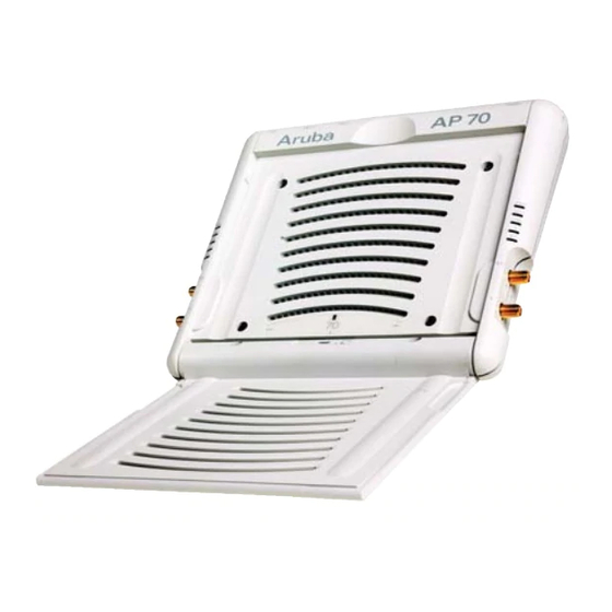
Page 44: Aruba Ap 70 Access Point
Product Specifications Chapter C Aruba AP 70 Access Point Part Number: AP-70 IGURE Aruba AP 70 0500159 Installation Guide November 2005... - Page 45 Product Specifications Chapter C Aruba AP 70 802.11 Specifications ABLE Description 802.11a 802.11b 802.11g Integral Dual, diversity supporting omni-directional, high gain as follows: Antenna 2.4-2.5 Ghz 4.46 dBi 5.150 Ghz 7.21 dBi 5.350 Ghz 6.49 dBi 5.850 Ghz 5.23 dBi Frequency 5.150 ~ 5.250...
- Page 46 Product Specifications Chapter C Aruba AP 70 802.11 Specifications (Continued) ABLE Description 802.11a 802.11b 802.11g Operating US & Canada: US & Canada: 11 US & Canada: 8 external Channels ETSI: 13 antenna ETSI: 13 Japan: 14 12 internal Japan: 14...
- Page 47 Product Specifications Chapter C Aruba AP 70 Characteristics (Continued) ABLE Description Physical Antenna Retracted: 167 x190 x 30 mm (6.57 x 7.48 x 1.18 in) (HxWxD): Antenna Deployed: 293 x 190 x 30 mm (11.54 x 7.48 x 1.18 in)
- Page 48 Aruba AP 70 Characteristics (Continued) ABLE Description Output Power 100 mW maximum (or lower as configured on the Aruba Mobility Controller to comply with local regulatory requirements) Environmental: Temperature: Operating: 0 to 50 C (32 to 122 Storage: 0 to 70...
-
Page 49: Related Documents
Product Specifications Chapter C Related Documents The following items are part of the complete documentation for the Aruba system: Aruba Quick Start Guide Aruba AP 70 Wireless Access Point Installation Guide (this document) Aruba Mobility Controller Installation Guide ArubaOS User Guide... - Page 50 { Item A | Item B } In the command examples, items within curled braces and separated by a vertical bar represent the available choices. Enter only one choice. Do not type the braces or bars. Aruba AP 70 0500159 Installation Guide November 2005...
-
Page 51: Contacting Aruba Networks
Support http://www.arubanetworks.com/support E-mail Sales sales@arubanetworks.com Support support@arubanetworks.com Telephone Numbers Main 408-227-4500 408-227-4550 Sales 408-754-1201 Support In the US: 800-WI-FI-LAN (800-943-4526)+ France: 33 (0) 170725559+44 (0) 2071275989+49 (0) Germany: 69380977228+ 00 1 All Other: 408-754-1200 Aruba AP 70 Installation Guide... -
Page 52: Proper Disposal Of Aruba Equipment
Specifically, restricted materials under the RoHS Directive are Lead (including Solder used in PCB's), Cadmium, Mercury, Hexavalent Chromium, and Bromine. Aruba declares compliance with the European Union (EU) WEEE Directive (2002/96/EC). For more information on WEEE, refer to: http://www.dti.gov.uk/sustainability/weee/...
Need help?
Do you have a question about the AP 70 and is the answer not in the manual?
Questions and answers