Alarm.Com ADC-T2000 Product Manual
Smart thermostat
Hide thumbs
Also See for ADC-T2000:
- Installation manual (16 pages) ,
- User manual (14 pages) ,
- Quick installation manual (2 pages)
Table of Contents
Advertisement
Advertisement
Table of Contents

Related Manuals for Alarm.Com ADC-T2000


Summary of Contents for Alarm.Com ADC-T2000
- Page 1 Smart Thermostat ADC-T2000 Product Manual...
- Page 3 Alarm.com Smart Thermostat Product Manual | 3 • Before installing or servicing the thermostat, • This thermostat should only be powered by 4 turn off power to the system at the circuit AA alkaline batteries or a listed class 2 power breaker.
-
Page 4: Box Contents
4 | Alarm.com Smart Thermostat Product Manual Box Contents: Thermostat Backplate Trim Plate (Optional) Drywall Screws (3) AA Batteries (4) Drywall Anchors (3) Wire Labels Recommended Tools: Needlenose Pliers Phillips Head Power Drill Pencil Screwdriver... -
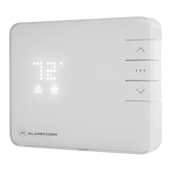
Page 5: Thermostat Overview
Alarm.com Smart Thermostat Product Manual | 5 Thermostat Overview MODE DOWN DISPLAY HEAT COOL RADIO Buttons Icons • UP ( ) Button – Adjust target temperature up. • HEAT ( ) Icon – Illuminated in HEAT or AUTO mode. • MODE ( ) Button –... -
Page 6: Location
6 | Alarm.com Smart Thermostat Product Manual Location If replacing an old thermostat, • Mount thermostat on an • Be aware of what is on the the new thermostat can be inside wall, approximately other side of the wall where the mounted in its place. -
Page 7: Preparation
Alarm.com Smart Thermostat Product Manual | 7 Preparation The Existing Thermostat CAUTION: DO NOT REMOVE the existing thermostat until power has been turned off 1. Test The System at the circuit breaker. Verify that the heating and/or cooling system is... - Page 8 8 | Alarm.com Smart Thermostat Product Manual TIP: Take another picture of the wires to • Disconnect all of the wires and remove the document connections for easy reference. Do existing thermostat. not disconnect wires before labeling them. TIP: Remember to secure the wires so they don’t fall into the wall.
-
Page 9: Install
Alarm.com Smart Thermostat Product Manual | 9 Install Your New Thermostat Install the Back Plate Wire Your New Thermostat • If you have R, connect it to RH. Use the bubble level provided Reconnect the wires to the • If you have RH & RC, remove on the back plate as a guide. -
Page 10: Insert Batteries
10 | Alarm.com Smart Thermostat Product Manual Insert Batteries Into the Thermostat The thermostat can be powered by battery or • Always replace the batteries at least once a year. 24 VAC. If a wall transformer is used to power This will protect the thermostat from damage and the thermostat, connect between C and RH. - Page 11 Alarm.com Smart Thermostat Product Manual | 11 Install Thermostat Body to Back Plate Verify that any excess wire is tucked back into the wall to allow room for the thermostat to sit flush against the back plate. Press the thermostat body firmly into the back plate mounted to the wall.
-
Page 12: Connect To The System
12 | Alarm.com Smart Thermostat Product Manual Connect the Thermostat to the System 1. Put the thermostat in OFF mode (No mode icons are lit). 2. Put the Z-Wave controller into inclusion mode. Refer to the controller documentation for more information. -
Page 13: Configure/Check The System
Alarm.com Smart Thermostat Product Manual | 13 Configure The System Check The System WARNING: Do not test the AC during cold The thermostat configuration will be done on weather or heat during hot weather. Wait your online account. Here you can configure the for mild weather to fully test the system. -
Page 14: Operation
14 | Alarm.com Smart Thermostat Product Manual Operation Display 5. Press the MODE ( ) button at any time to change the mode. 1. Press any button to wake the thermostat up. • The modes are HEAT ( ), COOL ( ), AUTO, 2. -
Page 15: Troubleshooting
Alarm.com Smart Thermostat Product Manual | 15 Troubleshooting Manual Configuration of HVAC System Heating or Cooling Doesn’t Turn On When on Thermostat the Set Point is Above or Below the Room Temperature If necessary, the system type (Normal or Heat... - Page 16 16 | Alarm.com Smart Thermostat Product Manual Exclude the Thermostat From the Z-Wave Batteries Drain Quickly Network If a thermostat is included using a “C” Wire, that If for some reason the thermostat must be information is saved in the network and cannot...
- Page 17 Alarm.com Smart Thermostat Product Manual | 17 Notices FCC NOTICE: This equipment has been tested and found to comply with the limits for a Class B digital This device complies with part 15 of the FCC device, pursuant to part 15 of the FCC Rules.
- Page 18 18 | Alarm.com Smart Thermostat Product Manual Notices IC NOTICE: Conformément à la réglementation d’Industrie Under Industry Canada regulations, this radio transmitter may only operate using an antenna Canada, le présent émetteur radio peut fonctionner of a type and maximum (or lesser) gain approved avec une antenne d’un type et d’un gain maximal...
- Page 20 Copyright © 2015 Alarm.com. All rights reserved. Alarm.com and the Alarm.com Logo are registered trademarks of Alarm.com.
Need help?
Do you have a question about the ADC-T2000 and is the answer not in the manual?
Questions and answers
Please tell me how to turn off the fan and control it manually. Thank you
To control the fan manually on the Alarm.com ADC-T2000 thermostat:
1. Put the thermostat in Off mode by pressing the button until no heating or cooling symbols are displayed. This means the system is not heating or cooling but still powered on.
2. Use the fan control option (available through the thermostat or Alarm.com app) to switch the fan mode. You can set it to:
- Auto: Fan runs only when heating or cooling is active.
- On: Fan runs continuously to circulate air.
To turn the fan off manually, set the fan mode to Auto and ensure the thermostat is in Off mode. This prevents the fan from running unless needed for heating or cooling.
This answer is automatically generated
How can I make it so that the thermostat doesn't constantly display the temperature?
To disable the constant temperature display on the Alarm.com ADC-T2000 thermostat, you need to operate it on battery power only. When running on battery power, the display will turn off after 5 seconds to conserve energy, while the thermostat continues to operate.
This answer is automatically generated