Table of Contents
Advertisement
Quick Links
Advertisement
Table of Contents

Related Manuals for AMC XA


Summary of Contents for AMC XA
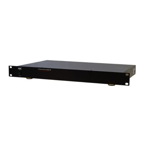
- Page 1 2/4 CHANNEL POWER AMPLIFIER...
-
Page 4: Installation Notes
1. Although the AMC XA is designed with high efficiency digital amplifiers, it still generates modest amounts of heat, adequate ventilation is required. We therefore recommend users not to place the XA amplifier on a soft surface such as a carpeted surface, etc. -
Page 5: Rear Panel
REAR PANEL CONNECTIONS/FRONT PANEL CONTROLS REAR PANEL 1. AC INLET 6. LOUDSPEAKER TERMINALS 2. 2CH/BRIDGE SWITCHES 7. AUDIO SENSE/ TRIGGER/ 3. INPUTS CONSTANT SWITCH 4. INPUT LEVEL CONTROLS 8. IR IN & IR OUT 5. RS232 Connector 9. FUSE FRONT PANEL 1. - Page 6 Each channel of the XA has its own, of loudspeakers to be connected. These independent level control. Before turning modes of operation are defined as on the XA for the first time, make sure follows;- that all level controls are set to their fully 2 CHANNEL MODE.
- Page 7 SWITCH installation. When the external trigger The remote power switch is located on voltage is set to 0V, the XA will be in the back panel of the AMC XA and standby mode and the voltage from the provides the following functions;...
- Page 8 IR signal from rooms or IR OUT of other units can be connected to the 3.5mm mini IR IN jack on the rear panel of XA. So, XA can be controlled by the IR remote control in each room through IR sensor. There is...
-
Page 9: Specifications
SPECIFICATIONS SPECIFICATIONS: BRIDGE MODE Power output into 8 ohms (20Hz~20KHz) ............90W With both channels driven Rated THD......................0.05% Damping factor ....................>100 Input sensitivity for 1W/90W into 8 ohm ..........110mV/1000mV 2 CHANNEL MODE Power output into 4 ohms (20Hz-20KHz) .............45W With all channels driven Rated THD. -
Page 10: Appendix I - Serial Communication Specifications
APPENDIX I - SERIAL COMMUNICATION System Commands SPECIFICATIONS Display unit identity: HARDWARE SPECIFICATION *RS232 asynchronous serial Display the brand name of this unit: communication *9600 bps, 8 bits, 1 stop bit, no parity BRAND<CR> *no flow control Display the model name of this unit: SOFTWARE SPECIFICATION Full command format: MODEL<CR>... -
Page 11: Safety Instruction
15. SERVICING stores, or National Fire Protection Association (Batterymarch Park, Quincy. MA 02269). The user should not attempt to service the appliance beyond that described in the operating instructions. All other servicing should be referred to qualified service personnel. AMC 21-3004... - Page 12 PN: 21-4081...
Need help?
Do you have a question about the XA and is the answer not in the manual?
Questions and answers