Advertisement
Table of Contents
- 1 Table of Contents
- 2 Overall Aspect
- 3 Safety Rules for All Tools
- 4 Features
- 5 Specification
- 6 Transportation & Install
- 7 Make Proper Tooth Selection
- 8 Minimum Room Space for Machine Operation
- 9 BI-Metal Speeds and Feeds
- 10 Use of Main Machine Parts
- 11 Maintaining
- 12 Trouble Shooting
- 13 Circuit Diagram
- 14 Parts Lists
- Download this manual
Advertisement
Table of Contents

Subscribe to Our Youtube Channel
Related Manuals for Hafco BS-13DS


Summary of Contents for Hafco BS-13DS
- Page 1 B030 30/7/09 HAFCO BS-13DS BANDSAW OPERATION PARTS MANUAL...
- Page 2 METAL CUTTING BAND SAW MACHINE MODEL: 330NAA INSTRUCTION MANUAL 330NAA-090728-R1...
- Page 3 WARNING Some dust created by power sanding, sawing, grinding, drilling, and other construction activities contains chemicals known to the State of California to cause cancer, birth defects or other reprodrctive harm. Some examples of these chemical are: ‧Lead from lead-based paints. ‧Crystalline silica from bricks, cement and other masonry products.
-
Page 4: Table Of Contents
Table Of Contents Page No 1 Overall Aspect ………………………………………………………………… 2 2 Safety Rules For All Tools …………………………………………………… 3 3 Specification …………………………………………………………………… 5 4 Features ……………………………………………………………………..… 5 5 Transportation & Install ……………………………………………………… 6 6 Minimum Room Space For Machine Operation …………………………… 7 7 Make Proper Tooth Selection ……………………………………………….. -
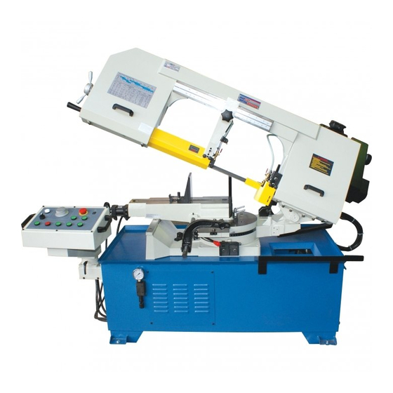
Page 5: Overall Aspect
Overall Aspect Control Panel Body Frame Change Speed Wheel Motor Cover Cutting Chip Move Vice Angle Sale Base... -
Page 6: Safety Rules For All Tools
WARNING: FAILURE TO FOLLOW THESE RULES MAY RESULT IN SERIOUS PERSONAL INJURY As with all machinery there are certain hazards involved with operation and use of the machine. Using the machine with respect and caution will considerably lessen the possibility of personal injury. However, if normal safety precautions are overlooked or ignored, personal injury to the operator may result. - Page 7 (8). DIRECTIONOF FEED. Feed work into a blade or cutter against the direction of rotation of the blade or cutter only. (9). ADJUST AND POSITION the blade guide arm before starting the cut. (10). KEEP BLADE GUIDE ARM TIGHT, A loose blade guide arm will affect sawing accuracy. (11).
-
Page 8: Specification
G. NOISE: A weighted sound pressure level : under80 dB. H. SAFETY DEVICE: Interlock switch on cutting area as soon as the cover of cutting area is open, machine will stop at once witch the function of this switch. Do not remove this switch from machine for any reason, and check its function frequently. -
Page 9: Transportation & Install
5.TRANSPORTATATION & INSTALLATION: 5-1.Unpacking 1. Transportation to desired location before unpacking, please use-lifting jack. (Fig. B) 2. Transportation after unpacking, please use heavy duty fiber belt to lift up the machine. Fig. B ALLWAYS KEEP PROPER FOOTING & BALANCE WHILE MOVING THIS MACHINE. 5-2.TRANSPORTATION OF MACHINE: As this machine weights 550kgs(1210lbs) it is recommended that the machine be transported with help of lifting jack. -
Page 10: Minimum Room Space For Machine Operation
safety wiring. (6) Keep machine always out from sun, dust, wet, raining area. 5-4.CLEAIG & LURICATING (1) Your machine has been coated with a heavy grease to protect it in shipping. This coating should be completely removed before operating the machine. Commercial degreaser, kerosene or similar solvent may be used to remove the grease from the machine, but avoid getting solvent on belts or other rubber parts. -
Page 11: Bi-Metal Speeds And Feeds
the round shape which aligns with the size of stock you are cutting. EXAMPLE: 4" (100mm) round, use a 3/4 Vari-Tooth. Tubing, Pipe, Structural ( Symbol : O H ^ ) Determine the average width of cut by dividing the area of the work-piece by the distance the saw blade must travel to finish the cut. - Page 12 Carbon 1008,1015,1020,1025 Steel 1035 1018,1021,1022 1026,1513 A36(SHAPES),1040 1042,1541 1044,1045 1060 1095 Ni-Cr-Mo 8615,8620,8622 Alloy Steel 4340,E4340,8630 8640 E9310 Tool Steel A-10 H-11,H-12,H-13 Stainless Steel 410,502 440C 304,324 304L 316,316L TELLTALE CHIPS Chips are the best indicators of correct feed force. Monitor chip information and adjust feed accordingly.
-
Page 13: Use Of Main Machine Parts
9.USE OF MAIN MACHINE PARTS 9-1.POWER SYSTEM AND CONTROL PANEL The electrical rating of your band saw is either with 230 volt-single phase, or 400 volt-3 phase, magnetic control. If saw arm is in home position and the power is on, the saw arm will be risen up automatically by Hydraulic Unit System when turn on the Hydraulic Unit System button. - Page 14 9. When discontinued cutting or reset cutting is necessary during operation, close the cylinder feeding valve, then push the stop button (F) Press emergency button (E) to shut-off the motor when in emergent situation. Before next operation, release (E) to get power. An automatic shut-off limit switch is provided to stop the motor when the cut is completed.
- Page 15 9-5.ADJUSTING BLADE TENSION AND BLADE TRACKING To tension the blade, turn the blade tension handle (A) (fig. 7) clockwise. A pointer and tension scale (B) is located underneath the wheel. The scale is graduated to indicate blade tension of 20,000, 30.000 and 35,000 pounds per square inch (psi).
- Page 16 9-9.BLADE AND COOLING SYSTEM The use of proper cutting fluid is essential to obtain maximum efficiency from a band saw blade. The main cause of tooth failure is excessive heat build-up. This is the reason that cutting fluid is necessary for long blade life and high cutting rates. cutting area and blade wheels should be kept clean at all time.
- Page 17 For front or rear cutting, move the sliding vise table by direct pushing. Be sure to put your hand ahead of (C) to prevent the contact with the pumper. Fig 18 is the Hydraulic Vise set. The hydraulic (B) movement is: turning the handle(A) and make the vise(C) to clamp working object, and push the bottom of Hydraulic Vise Clamp.
- Page 18 The gearbox should be drained and refilled after the first 50 hours of use and thereafter every 5 months, with Mobil Synthetic Gear Oil, SHC-636, ISO Viscosity Grade 680. This oil meets or exceeds American Gear Manufacturers Association (AG.M.A.) #8 compounded Cylinder Oil specifications.
-
Page 19: Maintaining
Always keep the floor dry to prevent slip or any accident. 10.MAINTAINING That's easier to keep machine in good condition or best performance by means of maintaining it at any time than remedy it after it is out of order. (1) Daily Maintenance (by operator) (a) Fill the lubricant before starting machine everyday. - Page 20 Premature Blade Dulling 1. Teeth too coarse 1. Use finer teeth 2. Too much speed 2. Decrease speed 3. Inadequate feed pressure 3. Decrease spring tension on side of 4.Hard spots or scale on material 4. Reduce speed, increase feed pressure 5.
- Page 21 Blade is twisting 1. Cut is binding blade. 1. Decrease reed pressure. 2. Too much blade tension 2. Decrease blade tension. Saw arm can not be raised 1.Improper setting of depth gauge 1. Press the emergency stop up after pushing the raising Button and RESET.
-
Page 22: Circuit Diagram
12. CIRCUIT DIAGRAM... - Page 23 330NAA...
-
Page 27: Parts Lists
PARTS LIST MODEL NO. 330NAA CODE NO PART NO DESCRIPTION SPECIFICATION NOTE 103005K Stand HW004 6.5*13-0.8t (M6) Washer HS229 M6x15L Hex. Socket Head Screw HW004 6.5*13-0.8t (M6) Washer HS229 M6x15L Hex. Socket Head Screw 103005K-1 Bracket A HW004B Washer HS334 M6X12L Hex. - Page 28 PARTS LIST MODEL NO. 330NAA CODE NO PART NO DESCRIPTION SPECIFICATION NOTE 21-5 HD817 1/8" Connector 21-6 103178 Spring 21-7 103174 Bush 21-8 M20XP1.5 HN009B Hex. Nut 21-9 POS 20 CAPOS20 Bearing 21-10 103176 Shaft 21-11 103175 Bracket 21-14 103177 Shaft 21-15 HS232...
- Page 29 PARTS LIST MODEL NO. 330NAA CODE NO PART NO DESCRIPTION SPECIFICATION NOTE HW105 Spring Washer HS246 M8x40L Hex. Socket Head Screw HW003 Washer HW006 Washer 101116 Spring CA51204 51204 Bearing 198051A Option Blade Tension Handle 103257 Option Handle Body 103254 Bracket HS519 M5x10L...
- Page 30 PARTS LIST MODEL NO. 330NAA CODE NO PART NO DESCRIPTION SPECIFICATION NOTE 85-3 HSC01 C-Retainer Ring 103027AS Bearing Shaft Assembly 85-1 103027A Bearing Shaft 85-2 CA609ZZ 609ZZ Bearing 85-3 HSC01 C-Retainer Ring 103028AS Eccentric Shaft Assembly 86-1 103028A Eccentric Shaft 86-2 CA609ZZ 609ZZ...
- Page 31 PARTS LIST MODEL NO. 330NAA CODE NO PART NO DESCRIPTION SPECIFICATION NOTE 105093 Wheel HW017 23*10.5-3 115-1 Washer HS230 M6x20L Hex. Socket Head Screw 103060 Cylinder Upper Support 103078 Pivot Pin HS422 M6x10L Hex. Socker Headless Screw HW005 Washer HS242 M8x20L Hex.
- Page 32 PARTS LIST MODEL NO. 330NAA CODE NO PART NO DESCRIPTION SPECIFICATION NOTE HS433 M8x25L Hex. Socker Headless Screw 103049 Blade Guard (Rear) HN006 Hex. Nut 191333 Spring 103133S 167S Brush Assemble 103133 167-1 Brush Shaft HE305 M6-1.0x40L 167-2 Cross Round Head Screw HW004 6.5*13-0.8t (M6) 167-3...
- Page 33 PARTS LIST MODEL NO. 330NAA CODE NO PART NO DESCRIPTION SPECIFICATION NOTE HS284 M12x50L Hex. Socket Head Screw 103058 Rack Support HW105 Spring Washer HS242 M8x20L Hex. Socket Head Screw 103056 Rack HK007 5X5X15L 103055 Acme Screw 103055G Acme Screw 101025 Feed Support HS242...
- Page 34 PARTS LIST MODEL NO. 330NAA CODE NO PART NO DESCRIPTION SPECIFICATION NOTE 105210 Scale HH001 ∮2x5L 262-1 Rivet 101113 M10x40L Knob HW009 ∮19x∮11x5t Bushing 101081A Fix Block 101037 2 Way Limit Block 266-1 101037A 2 Way Limit Block HW104 Spring Washer HS230 M6x20L Hex.
- Page 35 PARTS LIST MODEL NO. 330NAA CODE NO PART NO DESCRIPTION SPECIFICATION NOTE HW003 ø5.3*ø10Xt1mm Option Washer 300-3 HS558 M5-0.8P*8L Option Cross Round Head Screw 300-4 189073 Option Bracket 300-5 MFH2049 Motor 101090 (1422) 360V Belt 103098 Motor Pulley Cover HS519 M5x10L Cross Round Head Screw 103156...
- Page 36 PARTS LIST MODEL NO. 330NAA CODE NO PART NO DESCRIPTION SPECIFICATION NOTE 345-5 103127-3 ID1/4"x2.2tx143cm Net Tube 346S 103127S 3 Way Valve Assembly 346-1 HS232 M6x30L Hex. Socket Head Screw 346-2 105173 3 Way Valve 346-3 HD650 PT1/4"x1/4" Straight Connector 346-4 HD656 ∮12...
- Page 37 PARTS LIST MODEL NO. 330NAA CODE NO PART NO DESCRIPTION SPECIFICATION NOTE 382-2 103269B Rear Cover of ECB 382-3 HS519 M5X10L Cross Round Head Screw 382-4 103073E Cylinder Control Cover HN004 Hex. Nut HW004 Washer HS230 M6X20L Hex. Socket Head Screw HW004 Washer 103271PC...
- Page 38 PARTS LIST MODEL NO. 330NAA CODE NO PART NO DESCRIPTION SPECIFICATION NOTE HS519 M5x10L Cross Round Head Screw HS044 M8x10L Hex. Head Screw 480-1 151105-1 Adjustment Valve 151130 Bracket HW005B Washer M8X20L HS242 Hex. Socket Head Screw HW005B Washer M8X15L HS349 Hex.
- Page 39 PARTS LIST MODEL NO. 330NAA CODE NO PART NO DESCRIPTION SPECIFICATION NOTE 853-1 103063AA Cover 853S 103063KS 3PH/ 1/4HP Hydraulic Unit HS519 M5x10L Cross Round Head Screw HW103 Spring Washer 856-1 103172 Cross Round Head Screw HS240 M8x10L Hex. Socket Head Screw HW105 Spring Washer 105211...
- Page 40 MANUFACTURER: ADDRESS: SERIAL No.: PLEASE WRITE DOWN THE SERIAL NO. ON THIS BLOCK FROM THE NAME PLATE AFTER YOU RECEIVE THIS MACHINE.
Need help?
Do you have a question about the BS-13DS and is the answer not in the manual?
Questions and answers