Table of Contents
Advertisement
Advertisement
Table of Contents

Related Manuals for Hafco TS250SC


Summary of Contents for Hafco TS250SC
- Page 1 20/7/08 (W460) HAFCO ST1265 SAWBENCH PARTS MANUAL...
- Page 2 INSTRUCTIONS for 10” Table Saw w/Sliding Carriage Model: TS250SC FOR YOUR OWN SAFETY, READ ALL INSTRUCTIONS CAREFULLY BEFORE USING THIS MACHINE...
-
Page 3: Table Of Contents
Table of Contents 1. Getting to Know Your Table Saw....................1 2. Please Read First........................2 3. Safety............................2 3.1 SpeciÞ ed conditions of use....................2 3.2 General safety instructions....................2-3 3.3 Symbols used throughout these instructions................3 3.4 Safety devices........................3-4 4. Special Product Features......................4 5. Operating Elements......................4-5 6. -
Page 4: Getting To Know Your Table Saw
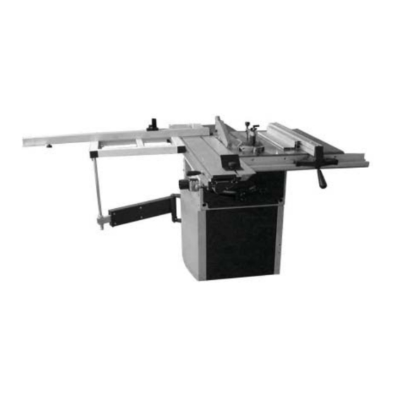
1. Getting to know your saw 1. Box Stand 12. Right Extension Table 2. ON/OFF Switch with Emergency Stop 13. Extractable Stop Rail 3. Saw Unit 14. Sliding Carriage 4. Miter Gauge 15. Swing Arm Assembly 5. Blade Guard 16. Sliding Table Frame Assembly 6. -
Page 5: Please Read First
General Hazard! 2. Please Read First! • Keep your work area tidy – a messy work area •4 Read these instructions before use. Pay invites accidents. special attention to the safety instructions. • Be alert. Know what you are doing. Set out to •... -
Page 6: Symbols Used Throughout These Instructions
• Ensure that when switching on (e.g. after • Damaged protection devices or parts must be servicing) no tools or loose parts are left on repaired or replaced by an qualiÞ ed specialist. or in the machine. • Do not operate the machine if the switch can •... -
Page 7: Special Product Features
Push stick • The push stick (P) (Figure 2) serves as an extension of the hand and protects against accidental contact with the saw blade. • Use push stick if the distance from the rip fence to the saw blade is more than 120 mm. Be sure the push stick be always at hand. -
Page 8: Initial Operation
6. Initial Operation Caution: This table saw is shipped in two packages: the master case and the sliding carriage carton. Figure 6 Installing side extension table Miter gage Unpacking the master case. Take away the • • The miter gage is used in making cross cuts in case panels and take out the main unit of the the workpiece. -
Page 9: Installing The Front Rail
6.2 Installing the front rail 6.3 Installing the Rear Extension Table Install the front rail needs following Install the rear rail needs following hardwares: hardware: 4-M8x25 mm cross cylinder head screws 2-M8x25 mm Hex Head Bolt 4-8 mm ß at washer 2-M8 mm Nut 4-M8 mm hex self-lock nuts 2-M8 mm Washer... -
Page 10: Installing The Riving Knife
4, Slide the rip fence back and forth. It should 6.7 Connection of dust collector move freely with about 2mm clearance below the rip fence. If it dosen’t, loosen the screws Danger! of the front rail, and adjust it up or down. •... -
Page 11: Installing The Sliding Carriage
The safety switch may ensure the machine Caution! not to run in case of the sliding carriage moving In order for the saw dust to be effectively led off away and may prevent people from been injured the chip ejection tube supplied has to be by the saw blade. - Page 12 6, Slide the sliding carriage onto the sliding table Check the surface alignment of the major from the left end. Slide it forward to the end, table and the sliding carriage. Adjust the gurb Þ x the sliding table tightly by two wing screws. screws on the support plate for micro (Figure 22 - 2) adjustment.
-
Page 13: Mains Connection
7. Operation Risk of injury! • This machine may only be operated by one person at a time. Other persons may stay only at a distance from the saw for the purpose of feeding or removing stock. • Before starting workoring, check to see that the followings are in proper working order: Figure 24 - power cable and plug;... -
Page 14: Sawing
2, Reposition auxiliary fence extrusion if 7.1 Sawing necessary: • For cutting the workpiece is evenly fed - Low edge (as shown) = for sawing thin stock, against the saw blade towards the rear of and with a tilted saw blade the table: - High edge = for cutting thick stock (max. -
Page 15: Care And Maintenance
7, Push the sliding carriage forward to cut 6, Loosen the saw blade spindle arbor nut with workpieces in a single pass. spanner (L.H. thread!). 8. Switch the machine off if no further cutting is 7, Take the outer blade collar and saw blade off to be done immediately afterwards. -
Page 16: Cleaning The Saw
8.2 Cleaning the saw 10. Repairs 1, Lay machine on its side. Danger! 2, Remove chips and saw dust with the vacuum Repairs to electric tools must be carried out by cleaner or brush: qualiÞ ed electricians only! - from saw blade setting guide elements •... -
Page 17: Wiring Diagrame
12. Wiring Diagrams Wiring Diagram 230V Wiring Diagram 400V... -
Page 18: Part Lists And Part Breakdown
13. Part Lists and Part Breakdown Part Description Part Description Arc plate Major Table Steel ring Front rail Self-lock nut M6 Cross cylinder head screw Mx25 Chip-case guide panel, front Cover plate Pan head screw M6x10 Hex head screw Mx30 Flat washer 6mm Flat washer 8mm Square, stop... - Page 19 Part Description Part Description Countersunk head screw M6x10 Ball bearing 80103 Bracket, motor Circlip 35 mm Flat washer 6 mm Pulley, spindle Left-hand hex head screw M8x10 Belt Ring plate, locking Quill tube Motor pulley Ball bearing 80301 Motor Pulley, drive Pan head screw M4x6 Flat washer 8mm Pan head screw M4x10...
- Page 24 Part Description Part Description ST11 Hex head screw M6x15 ST16 Hex nut M6 ST12 Pan head screw M6x20 ST17 Flat washer M6 ST13 Stand side panel ST18 Rubber feet ST14 Flat washer M6 ST19 Stand front panel ST15 Stand read panel...
- Page 25 Part Description Part Description Cam Lock RP14 Wing Screw Fence Handle RP15 Washer Hex Nut M8 RP16 “L” Fence Extrusion Adjust Screw RP17 Fence Pan Head Screw M4x10 RP19 Hex Head Screw M8x12 Hex Head Screw M6x16 RP20 Fence Head Lens RP21 Rub Piece...
- Page 26 Part Description MG11 Lock knob, longer MG12 Lock knob, shorter MG13 Flat washer M6 MG14 Clamp knob MG15 Clamp house MG16 Quick release button MG17 Lock tab MG18 Tapping screw ST4.2x9.5 MG19 Clamp screw MG20 Clamp holder MG21 Miter gauge base MG22 “T”...
- Page 27 Part Description Part Description End Cap Hex nut M8 Extractable Stop Rail Washer 8mm Scale I End Cap Stop Rail Extrusion Extension Arm Scale II Roller Screw M5x6 Screw M6X10 Scale III Washer 6mm Extension Stop Rail Shaft Set Screw M6x12 Bearing Guide Plate Shaft...
Need help?
Do you have a question about the TS250SC and is the answer not in the manual?
Questions and answers