Table of Contents
Advertisement
Contents
Chapter 1: Introduction .............................................. 1
Welcome ....................................................................... 1
About the Manual .......................................................... 2
Checklist........................................................................ 3
Standard Items ------------------------------------------------- 3
Optional Items -------------------------------------------------- 3
Recommendations ........................................................ 3
Features ........................................................................ 4
Chapter 2: Installation ................................................ 7
Quick Installation Table................................................. 7
Quick Jumper Setting Reference .................................. 8
Before You Begin .......................................................... 10
Static Electricity ------------------------------------------------ 10
Choosing a Case ---------------------------------------------- 11
How to Set Jumpers ------------------------------------------ 11
Preparing the Mainboard............................................... 13
Mainboard Guide ---------------------------------------------- 13
I/O Ports Side View ------------------------------------------- 15
Check the Jumper Settings --------------------------------- 15
Install the Mainboard in the Case-------------------------- 18
Connecting Power, Chassis Fan, and Panel------------ 19
Install Other Hardware .................................................. 21
Install the Processor ------------------------------------------ 21
Installing a Socket-370 Processor------------------------- 22
Install the Memory Modules--------------------------------- 24
Install a Hard Disk Drive and CD-ROM ------------------ 25
Installing a Floppy Diskette Drive-------------------------- 28
Using the Expansion Slots ---------------------------------- 29
Add-in Card Options ------------------------------------------ 31
Install Options and Extension Brackets ------------------ 32
Make the External Connections .................................... 34
Advertisement
Table of Contents

Related Manuals for ECS P6BAP-Me


Summary of Contents for ECS P6BAP-Me
-
Page 1: Table Of Contents
Contents Chapter 1: Introduction ..........1 Welcome ............... 1 About the Manual ............2 Checklist................ 3 Standard Items ------------------------------------------------- 3 Optional Items -------------------------------------------------- 3 Recommendations ............3 Features ................ 4 Chapter 2: Installation ..........7 Quick Installation Table..........7 Quick Jumper Setting Reference ........8 Before You Begin ............ -
Page 2: Important Information
AMD, K5, K6 are registered trademarks of Advanced Micro Devices Inc. Cyrix, M1 are registered trademarks of Cyrix Corporation. Other product names used in this manual are the properties of their respective owners and are acknowledged. Version 1.1 For marketing inquiries: mkt_tpe@ecs.com.tw For technical support: support_tpe@ecs.com.tw Website: http://www.ecs.com.tw... - Page 3 Appendix 1: Quick Jumper Setting Reference JP1: Clear CMOS memory jumper Use this 3-pin jumper to clear all the current data stored in the CMOS memory. Function Jumper Cap Normal operation Short pins 1-2 Clear CMOS Short pins 2-3 JP2: Keyboard power on jumper Use this 3-pin jumper to enable keyboard power on with hot keys or password.
-
Page 4: Chapter 1: Introduction
Welcome Congratulations on purchasing the P6BAP-Me mainboard. This mainboard features the latest VIA 82c693A/596B chipset. The mainboard includes a FC-PGA (Plastic Pin Grid Array) PGA370 processor socket. This feature means that you can install the mainboard with one of the FC-PGA Celerons or Cyrix Joshua processors. -
Page 5: Quick Installation Table
Quick Installation Table This chapter explains how to successfully install the mainboard into a computer case and build a working system. The installation procedure is as follows: Quick Jumper Provides a quick reference for the jumper Setting Reference settings on this mainboard. Before you Begin Provides advice on choosing a case, avoiding static electricity damage, and setting... -
Page 6: Chapter 3: Setup
About the Setup Utility This chapter explains how to use and modify the BIOS setup utility that is stored on the mainboard. The setup utility stores data about the mainboard components and the configuration of devices that are connected to it. This information is used to test and initialize components at start-up time and to make sure everything runs properly when the system is operating. - Page 7 The software for this mainboard is stored in the P6BAP-Me folder. Note: Never try to install software from a folder that is not specified for use with your mainboard.
-
Page 8: Canadian Department Of Communications
Safety Compliance Federal Communications Commission (FCC) This equipment has been tested and found to comply with the limits for a Class B digital device, pursuant to Part 15 of the FCC Rules. These limits are designed to provide reasonable protection against harmful interference in a residential installation. - Page 9 95/98 WinNT: This folder has hardware monitoring software for Windows NT ver. 4.0 P6BAP-Me Folder AUDIO, MODEM, MONITOR: These folders are empty. A readme file directs you to an alternate location with the required software. Note: Some folders are subdivided into different operating systems such as DOS, Windows 95, Windows NT, and so on.
- Page 10 Running the Support CD-ROM 1. Place the disk in your CD-ROM drive. If you are running Windows with Autoplay enabled, the opening screen of the CD appears automatically. Click on READ ME to read the latest instructions. 2. Click on the item BROWSE THE CD TITLE. This uses Windows Explorer to show the contents of the support CD.
- Page 11 PC-Cillin Anti-Virus Utility Anti-virus software is provided for DOS, for WIN95, and WIN 98. Log on to the appropriate directory for your operating system. For DOS, copy all the files in the DOS folder to your hard disk drive. For Windows 95, log on to the Disk 1 folder and run SETUP.
- Page 12 Modem Driver and Software Install the Modem driver from the sub-folders for Windows 95/98 or Windows NT4.0. Windows 95/98 The modem is a plug and play device so Windows 95/98 will automatically detect the presence of your modem. When the Plug and Play wizard begins to look for modem drivers, click on the button that says Have Disk and then browse or type in the pathname to the CMI8x58\modem\win9x folder.
- Page 13 SETUP.EXE. Follow the screen prompts to complete the installation. Mainboard (P6BAP-Me) Installation Notes All of the sub-folders in this folder are empty, with a short README file giving directions to alternate folders for the appropriate software.
- Page 14 Some options lead to tables of items that usually have a value on the right side. The value of the first item is highlighted, and you can use the cursor arrow keys to select any of the other values in the table of items. When an item is highlighted, you can change the value by pressing the PageUp or PageDown keys, or the Plus or Minus keys.
-
Page 15: How To Flash A New Bios
How to Flash a New BIOS You can install an updated BIOS for this motherboard that you can download from the manufacturer’s website. New BIOS may provide support for new peripherals, improvements in performance or fixes to address known bugs. Install a new BIOS as follows: 1. -
Page 16: Standard Cmos Setup Option
9. When the installation is complete, remove the floppy diskette from the diskette drive and restart your computer. If your mainboard has a Flash BIOS jumper, don’t forget to reset the jumper to protect the newly installed BIOS from being overwritten. Standard CMOS Setup Option This option displays a table of items which defines basic information about your system. -
Page 17: Bios Features Setup Option
able to configure it by setting the MODE to Large. If you’re not sure which MODE setting is required by your drive, set MODE to Auto and let the setup utility try to determine the mode automatically. Drive A and Drive B Default: 1.44M, 3.5 in., None These items define the characteristics of any diskette drive attached to the system. - Page 18 CPU Internal Core Speed Default: 233 MHz Use this item to automatically set up the mainboard for the kind of processor that you have installed. Set this item to the rated internal clock speed of the installed processor. If you set this to Manual, two new items appear: CPU Host Bus Frequency and CPU Frequency.
- Page 19 Processor Number Feature Default: Enabled Each Pentium-III processor cartridge is installed with a unique processor number. This number may be used for verification in internet transactions and e- commerce. If you prefer not to use or distribute the unique processor number, use this item to suppress the processor number.
-
Page 20: Chipset Features Option
HDD S.M.A.R.T. capability Default: Disabled SMART is an industry acronym for Self-monitoring, Analysis and Reporting Technology. If the documentation of your hard disk states that SMART is supported, you can enable this item. Report No FDD for WIN 95 Default: Yes If you are running a system with no floppy drive and using the Windows 95 OS, select Yes for this item to ensure compatibility with the Windows 95 logo certification. - Page 21 Bank 0/1 DRAM Timing Default: SDRAM 10ns Bank 2/3 DRAM Timing Default: SDRAM 10ns Bank 4/5 DRAM Timing Default: SDRAM 10ns These three fields define the speed of the memory chips that you can install in each of the three DIMM slots. For this motherboard, you must install SDRAM memory modules.
-
Page 22: Power Management Setup Option
On Board Modem Default: Enabled Use this item to enable or disable the onboard fax/modem that is integrated on this mainboard. Auto-Detect DIMM/PCI Clk Default: Enabled If this item is enabled, the system reduces EMI (electromagnetic interference) by turning off the clock generator signal to DIMM slots or PCI slots that are unoccupied. - Page 23 Power Management Default: User Define This item acts like a master switch for the power-saving modes and hard disk timeouts. If this item is set to Max Saving, doze and suspend mode, will occur after a short timeout. If this item is set to Min Saving, doze and suspend mode will occur after a longer timeout.
- Page 24 Soft-Off by PWR-BTTN Default: Instant-Off Under ACPI (Advanced Configuration and Power management Interface) you can create a software power down. In a software power down, the system can be resumed by Wake Up Alarms. This item lets you install a software power down that is controlled by the normal power button on your system.
-
Page 25: Welcome
Resume by Ring/Alarm Default: Disabled If you enable this item, the incoming calls to a fax/modem or incoming traffic to a netork adapter can resume the system from a power-saving mode. You might have to make a hardware connection on the system mainboard in order to implement this feature. -
Page 26: About The Manual
PNP/PCI Configuration Option This option displays a table of items that configures how PNP (Plug and Play) and PCI expansion cards operate in your system. PNP OS Installed Default: No If you install a Plug and Play operating system such as Windows 95 or 98, you can set this item to Yes. -
Page 27: Checklist
CPU to PCI Write Buffer Default: Enabled PCI Dynamic Bursting Default: Enabled PCI Master 0 WS Write Default: Enabled PCI Delay Transaction Default: Enabled PCI#2 Access #1 Retry Default: Disabled All of these five items determine how the system carries out read/write operations over the PCI bus. -
Page 28: Features
Integrated Peripherals Option This option displays a list of items which defines the operation of some peripheral items on the system’s input/output ports. OnChip IDE Channel0 Default: Enabled OnChip IDE Channel0 Default: Enabled Use these items to enable or disable the primary (channel0) and secondary (channel1) IDE channels that are integrated on this mainboard. - Page 29 IDE Primary Master UDMA Default: Auto IDE Primary Slave UDMA Default: Auto IDE Secondary Master UDMA Default: Auto IDE Secondary Slave UDMA Default: Auto Each IDE channel supports a master device and a slave device. This motherboard supports UltraDMA. UltraDMA technology provides faster access to IDE devices.
-
Page 30: Supervisor And User Password Settings
UART2 Duplex Mode Default: Half RxD, TxD Active Default: Hi,Lo IR Transmission delay Default: Enabled If you have selected an IR mode in UART Mode Select, use these items to configure the operation of the IR port. Onboard Parallel Port Default: 378/IRQ7 This item lets you disable the built-in parallel port, or enable it by assigning an I/O address and an Interrupt Request Line (IRQ). -
Page 31: Chapter 2: Installation
4. The system will ask you to confirm the new password by asking you to type it in a second time. Carefully type the password again and press Enter, or just press Enter if you are deleting a password that is already installed. -
Page 32: Quick Jumper Setting Reference
Quick Jumper Setting Reference If you are familiar with most of the material in this chapter, you can begin preparing the mainboard for installation by using this quick reference to begin setting the jumpers. A detailed description of the jumper setting appears later in this chapter. - Page 33 JP4: Set System Bus Frequency to 100 MHz Use this 3-pin jumper to set the system bus frequency. In the normal setting, the system automatically selects the correct frequency according to the kind of processor installed. In the Force 100 MHz setting, the system uses a 100 MHz system bus even if the processor is designed to operate with a 66 MHz bus.
-
Page 34: Before You Begin
Before You Begin Before you begin to install your P6BAP-Me mainboard, take some precautions to ensure that you avoid the possibility of damage to the product from static electricity. Ensure too that you are installing the mainboard into a suitable case. -
Page 35: Choosing A Case
Some features on the mainboard are implemented by cabling connectors on the board to indicators and switches on the system case. Ensure that your case supports all the features required. The P6BAP-Me mainboard can support one or two floppy diskette drives and four enhanced IDE drives. - Page 36 This illustration shows a 3-pin jumper. The jumper cap is placed on pins 2 and 3, so this jumper setting is SHORT PINS 2-3. This illustration shows the same 3-pin jumper. The jumper cap is placed on pins 1 and 2, so this jumper setting is SHORT PINS 1-2.
-
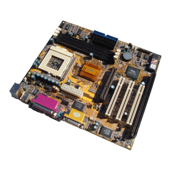
Page 37: Preparing The Mainboard
Preparing the Mainboard Mainboard Guide Use the following illustration and key to identify the components on your mainboard. DIMM1 DIMM2 CPUFAN1 DIMM3 Socket-370 FDD1 IDE2 SIR1 IDE1 ATX1 SIDEBAND1 CASEFAN1 CD IN1 AGP1 LED1 WOL1 CD IN2 PCI1 WOM1 PCI2 PCI3 MDM1 PANEL1... - Page 38 Key to Mainboard Components Component Description ISA1 8/16-bit ISA expansion slot PCI 1, 2, 3 3 x 32-bit PCI expansion slot AGP1 Slot for AGP graphics adapter SOCKET-370 Socket for Intel FC-PGA Celeron or Cyrix Joshua processor DIMM1, 2, 3 Slots for 168-pin memory modules FDD1 Connector for floppy disk drives...
-
Page 39: I/O Ports Side View
I/O Ports Side View LPT1 KBMPS2 USB1 COM1 COM2 Key to I/O Ports Component Description KBMPS2 PS/2 port for pointing device (upper port) PS/2 port for keyboard (lower port) LPT1 External parallel port JS1 (Upper) External game/MIDI port JS1 (Lower) Audio jacks for (left to right) line out, line in, microphone COM2... - Page 40 Check all the mainboard jumpers to ensure that the board is configured correctly. JP1: Clear CMOS Memory Jumper This jumper lets you erase the system setup settings that are stored in CMOS memory. You might need to erase this data if incorrect settings are preventing your system from operating.
- Page 41 JP4: Set System Bus Frequency Use this 3-pin jumper to set the system bus frequency. In the normal setting, the system automatically selects the correct frequency according to the kind of processor installed. In the Force 100 MHz setting, the system uses a 100 MHz system bus even if the processor is designed to operate with a 66 MHz bus.
-
Page 42: Install The Mainboard In The Case
Install the Mainboard in the Case The mainboard is drilled with a series of holes. Most system cases have mounting brackets installed in the case which correspond to the holes in the mainboard. You can secure the mainboard in the system case by placing the mainboard over the mounting brackets and driving screws through the mainboard into the mounting brackets. -
Page 43: Connecting Power, Chassis Fan, And Panel
Power Supply Unit Drive Cage Template Expansion Slots Connecting Power, Chassis Fan, and Panel After you have installed the mainboard into the system case, connect the chassis fan (if your case has one) to the power supply CASEFAN1on the mainboard. Then connect the case switches and indicators to the PANEL1 connector on the mainboard. - Page 44 Power Connector Locate the power cable from the case power supply unit and plug it into the ATX1 power connector. Chassis Fan If your case has a cooling fan installed, plug the cable from the fan into the mainboard fan power supply CASEFAN1. Panel Connector The mainboard PANEL1 connector has a standard set of switch and indicator connectors that are commonly found on ATX system cases.
-
Page 45: Install Other Hardware
Install Other Hardware Start installing the essential hardware required to get your system started. Install the Processor This mainboard has a Socket-370 processor socket. To choose a processor, you need to consider the performance requirements of the system and also the price of the processor. Performance is based on the processor design, the clock speed and system bus frequency of the processor, and the quantity of internal cache memory and external cache memory. -
Page 46: Installing A Socket-370 Processor
Installing a Socket-370 Processor To install the mainboard with a FC-PGA Celeron processor, follow the steps below. Locate the Socket-370 and CPUFAN1 Socket-370 CPUFAN1 Pin-1 corner Locking lever 1. On the mainboard, locate the socket-370 and CPUFAN1. 2. On the socket-370, pull the locking lever away from the socket to unhook it and then raise the locking lever to the upright position. - Page 47 Power cable Processor & heatsink/cooling fan assembly CPUFAN1 The mainboard must be configured to deliver the correct clock speed and the correct system bus for the kind of processor that you have installed. You can do this by using the system setup utility. The first time you start the system, immediately enter the setup system and make the appropriate settings.
-
Page 48: Install The Memory Modules
Install the Memory Modules For this mainboard, you must use 168-pin 3.3V non-buffered Dual In-line Memory Modules (DIMMs). The memory chips must be standard or registered SDRAM (Synchronous Dynamic Random Access Memory). The memory bus can run at 66 MHz or 100 MHz. If your processor operates over a 100 MHz system bus, you must install PC-100 memory that also operates over a 100 MHz bus. -
Page 49: Install A Hard Disk Drive And Cd-Rom
4. Install the DIMM module into the slot and press it carefully but firmly down so that it seats correctly. The latches at either side of the slot will be levered upwards and latch on to the edges of the DIMM when it is installed correctly. - Page 50 Installing a Hard Disk Drive 1. Install the hard disk drive into the drive cage in your system case. 2. Plug the IDE cable into the primary IDE channel on the mainboard IDE1. 3. Plug one of the connectors on the IDE cable into the IDE connector on the back edge of the hard disk drive.
- Page 51 Installing a CD-ROM Drive 1. Install the CD-ROM drive into the drive cage in your system case. 2. Plug the IDE cable into the primary IDE channel on the mainboard IDE1. 3. Plug one of the connectors on the IDE cable into the IDE connector on the back edge of the CD-ROM drive.
-
Page 52: Installing A Floppy Diskette Drive
Installing a Floppy Diskette Drive The mainboard has a floppy diskette drive interface and it ships with a diskette drive ribbon cable that supports one or two floppy diskette drives. You can install a 5.25” drive or a 3.5” drive with various capacities. The floppy diskette drive cable has one type of connector for a 5.25”... -
Page 53: Using The Expansion Slots
Using the Expansion Slots This mainboard has several expansion slots. You can install add-in cards into these slots to add new features to your system. In order to get your system started, you must install an add-in graphics adapter. The mainboard has three kinds of expansion slots. - Page 54 3. In the system case, remove the blanking plate from the slot in the system case that corresponds to the expansion slot that you are going to use. 4. Position the edge connector of the add-in card over the expansion slot.
-
Page 55: Add-In Card Options
Add-in Card Options The mainboard has some features that can be used by some types of add-in cards. SIDEBAND1 If you have installed a PCI Sound Blaster add-in card, you can use the cable provided with the card to plug into the SIDEBAND1 connector on the mainboard. -
Page 56: Install Options And Extension Brackets
Install Options and Extension Brackets On this mainboard you can install an optional infrared port. In order to use the built-in fax modem you must install the fax/modem extension bracket. If you have a 24-bit digital audio device, you can connect it to the SPDIF digital audio connector. - Page 57 Fax/modem Extension Bracket MDM1 The fax/modem extension bracket is supplied with this mainboard. 1. Locate the MDM1 fax/modem connector on the mainboard. 2. Remove the expansion slot blanking plate from the system chassis that is adjacent to the fax/modem connector. 3.
-
Page 58: Make The External Connections
Make the External Connections After you have installed the mainboard, make the connections to the external ports. LPT1 KBMPS2 USB1 COM1 COM2 1. KBMPS2 is a stack of two PS/2 mini-DIN ports. The upper port can be used by a PS/2 mouse or pointing device. The lower port can be used by a PS/2 keyboard. - Page 59 This chapter contains the following information: About the Manual explains how the information in this manual is organized Checklist comprises a list of the standard and optional components that are shipped with this mainboard Recommendations lists some Do’s and Don’ts from the manufacturer to help ensure reliability and performance from this product Features highlights the functions and components that make this...
- Page 60 Compare the contents of your mainboard package with the standard checklist below. If any item is missing or appears damaged, please contact the vendor of your mainboard package. Standard Items 1 x P6BAP-Me Mainboard 1 x Cable/Bracket Pack Diskette drive ribbon cable DMA 66 IDE drive ribbon cable This User’s Manual...
- Page 61 Features The key features of this mainboard are the advanced VIA 82c693A/596B chipset, and the support for FC-PGA processors. You can choose to develop a low-cost value system or a high-performance workstation. Support for FC-PGA Celeron and Cyrix Joshua Processors This mainboard support two kinds of processors FC-PGA Celerons, and Cyrix FC-PGA Joshua processors.
- Page 62 Optimized Chipset This board uses the VIA 82c693A/596B chipset. The 82c693A forms the north bridge and supports system buses of 66, 100 and 133 MHz. It is AGP Rev. 1 compliant and supports 3.3v AGP devices operating over a 66/133 MHz bus. The memory bus supports the fastest access (X-1-1-1) for both 66, 100 and 133 MHz operation.
- Page 63 Expansion Options Although this is a micro-ATX board, it has a generous allocation of expansions slots. One AGP slot is available for the installation of an Accelerated Graphics Port graphics adapter. Three 32-bit PCI slots can be used by PCI expansion cards. One legacy 8/16-bit ISA slot can be used by ISA cards.
- Page 64 JP4: Set System Bus Frequency to 100 MHz Use this 3-pin jumper to set the system bus frequency. In the normal setting, the system automatically selects the correct frequency according to the kind of processor installed. In the Force 100 MHz setting, the system uses a 100 MHz system bus even if the processor is designed to operate with a 66 MHz bus.
- Page 65 Panel Connector The mainboard PANEL1 connector has a standard set of switch and indicator connectors that are commonly found on ATX system cases. Use the illustration below to make the correct connections to the case switches and indicators. 22 21 PANEL1 Power SW 21-22 19-20...
- Page 66 Utility Folder Installation Notes ........56 CMI8X38 Folder Installation Notes ....... 57 Audio Software------------------------------------------------- 57 Modem Driver and Software-------------------------------- 58 VIA Folder Installation Notes......... 58 GL520SM Folder Installation Notes ......59 Mainboard (P6BAP-Me) Installation Notes ....59 Appendix 1: Quick Jumper Setting Reference..60...
Need help?
Do you have a question about the P6BAP-Me and is the answer not in the manual?
Questions and answers