Table of Contents
Advertisement
Quick Links
Advertisement
Table of Contents

Related Manuals for ECS P6LX-A


Summary of Contents for ECS P6LX-A
- Page 1 P6LX-A Mainboard User’s Manual...
- Page 2 P6LX-A User’s Manual Table Of Contents – 2 FCC & DOC Compliance FCC & DOC Compliance FCC & DOC Compliance FCC & DOC Compliance FCC & DOC Compliance Federal Communications Commission Statement Federal Communications Commission Statement Federal Communications Commission Statement...
-
Page 3: Table Of Contents
P6LX-A User’s Manual Table Of Contents – 3 1: P6LX-A Package & Product Information .... 1.1 Manual Features ................1.1 Package Contents ............... 1.3 Mainboard Features ............1.4 Component Information ............. 1.6 Expansion Slots ................1.6 Memory Sockets & Modules ............1.7 CPU Socket &... - Page 4 Adding SCSI Devices ............3.15 SCSI Device IDs ................3.16 SCSI Termination ................3.16 Installing an AGP Card ............3.16 4: P6LX-A Reference Information ......4.1 Using This Section ............... 4.1 Jumper Configuration & Connector Summary ....4.3 The AGP Slot ............... 4.8 The RAIDport™...
-
Page 5: 1: P6Lx-A Package & Product Information
Component Information 1: P6LX-A Package & Product Information This manual contains all the information you’ll need to use the P6LX-A mainboard. Please take a moment to familiarize your- self with the design and organization of the manual. Manual Features This manual is divided into four sections: •... - Page 6 P6LX-A User’s Manual 1: Package & Product Information – 1.2 The manual uses some icons to call your attention to impor- tant information. The icons appear in the sidebar and represent the following: • Important information • A recommendation or good idea •...
-
Page 7: Package Contents
P6LX-A User’s Manual 1: Package & Product Information – 1.3 Package Contents The P6LX-A mainboard package contains the following items. Please inspect the package contents and confirm that everything is there. If anything is missing or damaged, call your vendor for instructions before proceeding. -
Page 8: Mainboard Features
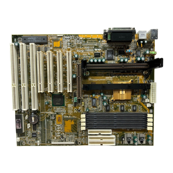
P6LX-A User’s Manual 1: Package & Product Information – 1.4 Mainboard Features This mainboard is a highly integrated ATX design that incor- porates many features on the board. The mainboard includes the following features: • Slot 1 CPU slot supports Pentium II CPUs up to 333MHz •... - Page 9 P6LX-A User’s Manual 1: Package & Product Information – 1.5 Game Parallel Mouse Mic, Line-In, Line-Out COM1 COM2 Keybd IR headers J11, J12 CD-In J29, J26, J28 CPU Slot ISA 3, 2, 1 PCI 4,3,2,1 ATX Power AGP Slot RAID port...
-
Page 10: Component Information
P6LX-A User’s Manual 1: Package & Product Information – 1.6 Component Information This section is a brief description of the components on the mainboard that you might need to know about if you want to upgrade or change your system configuration. If your mainboard is already installed in a system, it isn’t necessary for you to re-... -
Page 11: Memory Sockets & Modules
P6LX-A User’s Manual 1: Package & Product Information – 1.7 The RAID port ™ Slot Extension The slot extension to PCI4 is for the Adaptec RAIDport™ tech- nology that allows you to add an Adaptec ARO-1130 or compat- ible RAID (Redundant Array of Independent Disks) controller card. -
Page 12: Cpu Socket & Cpu
P6LX-A User’s Manual 1: Package & Product Information – 1.8 CPU Socket & CPU The Slot 1 CPU slot supports the full range of Pentium II CPUs from Intel. The mainboard comes with a “retention module” which mounts on the mainboard to provide guide rails and latch recep- tacles for the latches on the Pentium II. -
Page 13: 2: Using Your Mainboard
P6LX-A User’s Manual 2: Using Your Mainboard – 2.1 In This Section: System Controls Hardware Features The Retention Module Firmware & Software 2: Using Your Mainboard This section covers the system control features and status in- dicators that connect to the mainboard, some of the hardware features and provides an overview of the software that comes with or is built-into the mainboard. - Page 14 P6LX-A User’s Manual 2: Using Your Mainboard – 2.2 Hardware Control & Indicator Connectors Feature Function Power Status LED When lighted indicates that system is turned on Suspend Switch Puts the system into Suspend state under Operating Systems that support this power manage-...
-
Page 15: Cmos Setup Utility Controls
P6LX-A User’s Manual 2: Using Your Mainboard – 2.3 CMOS Setup Utility Controls Two sections of the CMOS Setup Utility allow you to config- ure how some of your system’s features work. These are: • BIOS Features Setup • Power Management Setup The CMOS Setup Utility is a program that is permanently stored in the BIOS chip on the mainboard. - Page 16 P6LX-A User’s Manual 2: Using Your Mainboard – 2.4 CMOS Setup Utility – Virus Warning – When enabled, monitors the BIOS Features Setup primary hard disk boot sec- This section of the setup utility tor and warns of any attempt allows you to configure some to write to it.
- Page 17 P6LX-A User’s Manual 2: Using Your Mainboard – 2.5 CMOS Setup Utility – You can use the Min Saving Power Management Setup or Max Saving default modes This section of the setup utility or you can configure the allows you to configure the...
-
Page 18: Hardware Features
P6LX-A User’s Manual 2: Using Your Mainboard – 2.6 Hardware Features This section is a brief overview of information about the mainboard’s hardware features. Onboard Ports There are several external ports on the mainboard. These are ports standard to most personal computers: •... - Page 19 P6LX-A User’s Manual 2: Using Your Mainboard – 2.7 CMOS Setup Utility – Integrated Peripherals This section enables and con- This section of the setup utility figures the optional USB and configures the IDE and Floppy Infrared features. controllers and the settings for...
- Page 20 P6LX-A User’s Manual 2: Using Your Mainboard – 2.8 Case Security The mainboard has a case security feature that will warn if the system case or ‘chassis’ has been opened since the last time the system was used. There is a photoelectric cell mounted on the mainboard that is active when the system is turned off and will detect the case being opened.
- Page 21 P6LX-A User’s Manual 2: Using Your Mainboard – 2.9 LAN Wake-Up The J40 connector on the mainboard is for connecting a signal cable from a LAN card that supports a LAN wake-up feature. When a LAN card that supports this is installed and connected to the mainboard via this connector, the system will wake up from Suspend mode when the system is accessed via the LAN.
-
Page 22: Optional Hardware Connectors
P6LX-A User’s Manual 2: Using Your Mainboard – 2.10 Optional Hardware Connectors There are additional feature connectors on the mainboard for optional ports. These require optional external port hardware. The Onboard SCSI Connectors & Controller The two SCSI connectors on the mainboard are controlled by the onboard Adaptec SCSI controller. - Page 23 P6LX-A User’s Manual 2: Using Your Mainboard – 2.11 The Ultra Wide SCSI port will support up to fifteen devices, the Wide SCSI port will support up to seven. If you connect an array to one of the ports, you can still use the other port to con- nect other SCSI devices, for example, a SCSI CD–ROM drive.
-
Page 24: The Cpu Retention Module
P6LX-A User’s Manual 2: Using Your Mainboard – 2.12 IR Ports There is one standard and one optional connector on the main- board which support an IR (infrared) port module that enables wireless communication between the computer and other com- puters and devices with an infrared port. - Page 25 P6LX-A User’s Manual 2: Using Your Mainboard – 2.13 1. Take precautions against static electric discharge before you start. It is best to have an anti-static surface to place the main- board on while you work on it and also an anti-static wrist strap.
-
Page 26: Firmware & Software
P6LX-A User’s Manual 2: Using Your Mainboard – 2.14 Firmware & Software The mainboard hardware is supported by both firmware and software components. Firmware is software that is stored on a chip on the board rather than on disk media. - Page 27 P6LX-A User’s Manual 2: Using Your Mainboard – 2.15 CMOS Setup Utility – This is the main screen for the setup utility from which you access its various sections. The function and use of each section is covered in Section...
-
Page 28: Flashing The Bios
P6LX-A User’s Manual 2: Using Your Mainboard – 2.16 Flashing The BIOS This mainboard uses the Award BIOS. The BIOS is stored on a programmable flash memory chip on the mainboard. Updates to the BIOS can be installed by installing a new BIOS file on the flash chip, which replaces the existing one. -
Page 29: 3: Reconfiguring Your Mainboard
P6LX-A User’s Manual 3: Reconfiguring Your Mainboard – 3.1 In This Section: Installing Expansion Cards Adding System Memory Installing A CPU Upgrade Adding An IDE Peripheral Adding SCSI Devices Installing An AGP Card 3: Reconfiguring Your Mainboard This section explains how to install new hardware on your mainboard. -
Page 30: Configuring Expansion Card Resources In Cmos Setup
P6LX-A User’s Manual 3: Reconfiguring Your Mainboard – 3.2 PCI Cards & Slots With very few exceptions, any PCI expansion card you are likely to get will be Plug an Play compliant. If you are using an Operating System that supports PnP, such as Windows 95, you... - Page 31 P6LX-A User’s Manual 3: Reconfiguring Your Mainboard – 3.3 CMOS Setup Utility – PnP/PCI Configuration If you install an Operating Sys- This is the default screen for tem that supports Plug and this section when Setup De- Play, such as Windows95, faults are loaded.
- Page 32 P6LX-A User’s Manual 3: Reconfiguring Your Mainboard – 3.4 CMOS Setup Utility – Legacy cards, by definition, PnP/PCI Configuration are not PnP compliant and When ‘Resources Controlled must be manually configured By’ is set to ‘Manual’ you can individually configure the IRQ if they require an IRQ or DMA channel.
-
Page 33: Adding System Memory
P6LX-A User’s Manual 3: Reconfiguring Your Mainboard – 3.5 Adding System Memory There are some requirements you must follow if you want to install system memory. The memory subsystem has four 168- pin DIMM sockets which function independently. This main- board supports both EDO DRAM and SDRAM (Synchronous DRAM) modules. - Page 34 P6LX-A User’s Manual 3: Reconfiguring Your Mainboard – 3.6 DIMM1 DIMM2 DIMM3 DIMM4 Retaining Clamp DIMM Sockets The picture above shows the Modules press into place memory module sockets in and are held in position by a detail. The sockets are num-...
- Page 35 P6LX-A User’s Manual 3: Reconfiguring Your Mainboard – 3.7 Installing Memory Modules To install a DIMM module, look at the module and note the position of the shorter section of the connector edge that plugs into the DIMM socket. Note the position of the shorter section of the socket.
-
Page 36: Installing A Cpu Upgrade
P6LX-A User’s Manual 3: Reconfiguring Your Mainboard – 3.8 Installing A CPU Upgrade If you are installing this mainboard it will not have a CPU installed unless your vendor installed one when you purchased the board. If the mainboard is installed in a system, there will already be a CPU installed. -
Page 37: Cpu Jumper Table & Illustrations
P6LX-A User’s Manual 3: Reconfiguring Your Mainboard – 3.9 CPU Jumper Table & Illustrations The next two pages show the CPU jumper settings. The set- tings are listed in the tables as follows: • For a two-pin jumper, On, if the cap is in place, and Off, if the cap is not in place. - Page 38 P6LX-A User’s Manual 3: Reconfiguring Your Mainboard – 3.10 CPU Jumper Settings Function Jumper Settings Internal 2.0x 1-2, 3-4, 5-6, 7-8 Clock Factor 2.5x 3-4, 5-6, 7-8 3.0x 1-2,5-6, 7-8 3.5x 5-6, 7-8 (233MHz CPU) 4.0x 1-2, 3-4, 7-8 (266MHz CPU) 4.5x...
- Page 39 P6LX-A User’s Manual 3: Reconfiguring Your Mainboard – 3.11 Jumper Locations The illustration above shows the location of the jumpers on the mainboard.
-
Page 40: Adding An Ide Peripheral
P6LX-A User’s Manual 3: Reconfiguring Your Mainboard – 3.12 Adding An IDE Peripheral This section covers some aspects of installing internal IDE pe- ripheral devices as they relate to the mainboard. The onboard Enhanced IDE controller supports up to four devices, two per IDE channel. - Page 41 P6LX-A User’s Manual 3: Reconfiguring Your Mainboard – 3.13 CMOS Setup Utility – You can also set the transfer Integrated Peripherals mode for each device manu- The illustration above shows ally, although we recom- the Setup Defaults settings for mend using the default set- this screen.
-
Page 42: Installing Ide Devices
P6LX-A User’s Manual 3: Reconfiguring Your Mainboard – 3.14 Installing IDE Devices The mainboard’s Enhanced IDE controller supports four de- vices in two channels, IDE1 and IDE2. These are called the Pri- mary and Secondary IDE channels. Each channel supports two devices, the first device is called the Master device and the second the Slave device. -
Page 43: Adding Scsi Devices
P6LX-A User’s Manual 3: Reconfiguring Your Mainboard – 3.15 IDE Devices & CMOS Setup When you install a new hard disk drive its parameters will be automatically detected by the BIOS and entered in the Standard CMOS Setup section of the CMOS Setup utility if you use the Optimum Settings, which automatically detect any new hard disk drive. -
Page 44: Scsi Device Ids
P6LX-A User’s Manual 3: Reconfiguring Your Mainboard – 3.16 SCSI Device IDs Each SCSI connector can support up to seven SCSI devices. Each SCSI device in the chain must have a unique identification number to identify itself to the controller. You set the ID number on the device hardware. -
Page 45: 4: P6Lx-A Reference Information
CPU Information Memory Configurations CMOS Setup Utility 4: P6LX-A Reference Information This section is a summary of the P6LX-A’s specifications and settings. Using This Section The information in this section is presented in a summary for- mat to make it easy to find specific information. If you need re-... - Page 46 P6LX-A User’s Manual 4: Reference Information – 4.2 Game Parallel Mouse Mic, Line-In, Line-Out COM1 COM2 Keybd IR headers J11, J12 CD-In J29, J26, J28 CPU Slot ISA 3, 2, 1 PCI 4,3,2,1 ATX Power AGP Slot RAID port DIMM1...
-
Page 47: Jumper Configuration & Connector Summary
P6LX-A User’s Manual 4: Reference Information – 4.3 Jumper Configuration & Connector Summary This section lists the jumper setting options for this mainboard and the onboard connectors. The settings are listed as follows: • The two pins shorted by a jumper cap on a three-or-more-pin jumper, e.g. - Page 48 P6LX-A User’s Manual 4: Reference Information – 4.4 CPU Jumper Settings Function Jumper Settings Internal 2.0x 1-2, 3-4, 5-6, 7-8 Clock Factor 2.5x 3-4, 5-6, 7-8 3.0x 1-2,5-6, 7-8 3.5x 5-6, 7-8 (233MHz CPU) 4.0x 1-2, 3-4, 7-8 (266MHz CPU) 4.5x...
- Page 49 P6LX-A User’s Manual 4: Reference Information – 4.5 JP3: Clear CMOS JP1: Internal Clock Factor Clear Normal 3.5X 4.0X JP6: CPU Mode Normal Turbo 4.5X JP5: SCSI Hi-Byte SCSI BIOS Control 5.0X Always Enable...
- Page 50 P6LX-A User’s Manual 4: Reference Information – 4.6 Onboard Connectors Name: Function Description J1: Keyboard Stacked PS/2 ports, keyboard lower, mouse upper & Mouse J3: Serial Port Two Onboard serial port is COM2, can set to COM4 J4: Serial Port One...
- Page 51 P6LX-A User’s Manual 4: Reference Information – 4.7 Name: Function Description J20: USB Dual stacked external USB ports J21: Modem Connects to internal modem for system wake-upon Wake-up modem ring J22: Wide SCSI Onboard 50-pin SCSI port connector, uses supplied...
-
Page 52: The Agp Slot
P6LX-A User’s Manual 4: Reference Information – 4.8 The AGP Slot The AGP (Accelerated Graphics Port) slot is for an AGP dis- play card. With the Optimum Settings loaded in the BIOS Setup Utility the AGP has a default memory aperture of 4MB, expand- able to 256MB. -
Page 53: System Memory Specifications
P6LX-A User’s Manual 4: Reference Information – 4.9 System Memory Specifications The memory subsystem on this mainboard has four 168-pin DIMM sockets. The sockets function independently and can use either EDO DRAM or SDRAM unbuffered 3.3–Volt modules. Single or double-sided modules from 8MB to 128MB are sup- ported up to a total memory capacity of 512MB. -
Page 54: Cmos Setup Utility Summary
P6LX-A User’s Manual 4: Reference Information – 4.10 CMOS Setup Utility Summary This section explains the entries in the CMOS Setup Utility program. This utility is permanently stored on the BIOS chip on the mainboard. It creates a record of the mainboard’s and some system configuration information and stores it in battery-sup- ported memory on the mainboard. - Page 55 P6LX-A User’s Manual 4: Reference Information – 4.11...
-
Page 56: Standard Cmos Setup
P6LX-A User’s Manual 4: Reference Information – 4.12 Menu Commands If you look at the lower portion of the screen illustration you’ll see a section that lists the control commands for this level of the program. You execute a command by pressing the key for that command. -
Page 57: Load Bios Defaults
P6LX-A User’s Manual 4: Reference Information – 4.13 • Load BIOS Defaults Loads minimum settings from the BIOS ROM. • Load Optimum Settings Loads optimized settings from the BIOS ROM. • Integrated Peripherals Settings for the IDE channels and onboard ports •... - Page 58 P6LX-A User’s Manual 4: Reference Information – 4.14 Standard CMOS Setup To enter this section, highlight this menu item in the main menu and press the Enter key. The screen above will appear. Menu Commands If you look at the lower portion of the screen illustration you’ll see a section that lists the control commands for this level of the program.
- Page 59 P6LX-A User’s Manual 4: Reference Information – 4.15 Select Item You can use the arrow keys on your keyboard to move around the screen and select a menu item. An item is highlighted when it is selected. Change Color You can change the program color scheme by pressing Shift +...
- Page 60 P6LX-A User’s Manual 4: Reference Information – 4.16 Large Hard Disk Modes The last of the drive parameter entries – Mode – has four op- tions, Normal, LBA, Large and Auto. The Mode settings are for IDE hard disks only.
- Page 61 P6LX-A User’s Manual 4: Reference Information – 4.17 Highlight the listing after each drive name and select the ap- propriate entry. Floppy 3 Mode Support 3 Mode is a Japanese 3.5-inch floppy disk drive specification. If this type of drive is installed you should enable this feature.
- Page 62 P6LX-A User’s Manual 4: Reference Information – 4.18 BIOS Features Setup To enter this section of the Setup program, highlight this menu item in the main menu and press the Enter key. The following screen will appear.
- Page 63 P6LX-A User’s Manual 4: Reference Information – 4.19 Menu Commands If you look at the lower portion of the screen illustration you’ll see a section that lists the control commands for this level of the program. You execute a command by pressing the key for that command.
- Page 64 P6LX-A User’s Manual 4: Reference Information – 4.20 Virus Warning This protects the primary hard disk’s boot sector and partition table from infection. Any attempt to write to them will halt the system and produce a warning message. If this happens, you can either allow the system to continue or stop it and boot from a virus-free bootable floppy disk.
- Page 65 P6LX-A User’s Manual 4: Reference Information – 4.21 Swap Floppy Drive This switches the floppy drive assignments so that drive A is treated as drive B: and drive B: as drive A: under DOS. The de- fault setting is Disabled.
- Page 66 P6LX-A User’s Manual 4: Reference Information – 4.22 PCI/VGA Palette Snoop If your video display card has an MPEG card attached to the feature connector, the display may invert to black on white while booting. If this happens, set this line to Enabled to correct the problem.
- Page 67 P6LX-A User’s Manual 4: Reference Information – 4.23 Chipset Features Setup To enter this section of the Setup program, highlight this menu item in the main menu and press the Enter key. The screen above will appear. Everything on this screen is either an optimum set- ting or set automatically when auto-configuration is active.
- Page 68 P6LX-A User’s Manual 4: Reference Information – 4.24 Memory Hole At 15M–16M Some special add-on cards require a 1MB address space be- tween 15 and 16MB. The documentation for this type of card should tell you if it needs this. The default setting is Disabled.
- Page 69 P6LX-A User’s Manual 4: Reference Information – 4.25 Power Management Setup To enter this section of the Setup program, highlight this menu item in the main menu and press the Enter key. The screen above will appear. Menu Commands The menu commands for this screen are the same as for the...
- Page 70 P6LX-A User’s Manual 4: Reference Information – 4.26 What Power Management Does Power management lets you set up your computer to save electricity when it is not actively in use by putting the system into progressively greater power saving modes. In the power man-...
- Page 71 P6LX-A User’s Manual 4: Reference Information – 4.27 Video Off After This governs when the video display gets turned off. The op- tions are: Suspend Off after system enters Suspend mode Standby Off after system enters Standby mode Doze Off after system enters Doze mode...
- Page 72 P6LX-A User’s Manual 4: Reference Information – 4.28 HDD Power Down This shuts down IDE hard disks that support a power saving mode after a specified time period. The settings range from 1 to 15 minutes and can be set manually when power management is in User Define mode.
- Page 73 P6LX-A User’s Manual 4: Reference Information – 4.29 ZZ Active In Suspend This item puts the cache controller into sleep mode when the system is in Suspend mode to achieve additional power saving. The default setting is Disabled, the option is Enabled.
- Page 74 P6LX-A User’s Manual 4: Reference Information – 4.30 Break Event From Suspend The two lines in this section control whether the system will wake-up if either of the events noted occur. The defaults are shown on the screen illustration on the next page.
- Page 75 P6LX-A User’s Manual 4: Reference Information – 4.31 PNP/PCI Configuration To enter this section of the Setup program, highlight this menu item in the main menu and press the Enter key. The following screen will appear. Menu Commands The menu commands for this screen are the same as for the...
- Page 76 P6LX-A User’s Manual 4: Reference Information – 4.32 Resources Controlled By When this line is set to Auto the BIOS will automatically con- figure IRQ and DMA resources. This is the recommended set- ting. If you set this line to Manual, the screen changes as shown above and allows manual configuration.
- Page 77 P6LX-A User’s Manual 4: Reference Information – 4.33 PCI IDE IRQ Map To Most of PCI IDE cards are non-PCI compliant. This line de- fines the IRQ Routing to make them work properly. The avail- able settings are: PCI-AUTO (default)
- Page 78 P6LX-A User’s Manual 4: Reference Information – 4.34 Load BIOS Defaults To use this command highlight it in the main menu and press Enter. A message will appear asking if you want to load the BIOS Defaults. Press the Y key and then the Enter key. The BIOS de- fault settings will load.
-
Page 79: Integrated Peripherals
P6LX-A User’s Manual 4: Reference Information – 4.35 Integrated Peripherals This section sets the IDE transfer mode for all IDE channels. It also configures the other onboard ports. Menu Commands The menu commands for this screen are the same as for the... - Page 80 P6LX-A User’s Manual 4: Reference Information – 4.36 IDE HDD Block Mode Enables hard disk drive block transfer mode . The setting op- tions are: Enabled (default) Disabled On-Chip Primary/Secondary PCI IDE Enables or Disables the Primary or Secondary PCI controllers.
- Page 81 P6LX-A User’s Manual 4: Reference Information – 4.37 Onboard FDD Controller Enables or Disables the onboard Floppy Drive controller. Onboard Serial Port 1/2 Sets the I/O address for serial ports 1 & 2. 3F8/IRQ4 Onboard serial port COM1 default 2F8/IRQ3...
- Page 82 P6LX-A User’s Manual 4: Reference Information – 4.38 Onboard Parallel Port Sets the I/O address for the onboard parallel port. The setting options are: 378H/IRQ7 (default) Disabled 278H/IRQ5 3BCH/IRQ7 If you set this option to ‘Disabled’, the next option, ‘Onboard...
- Page 83 P6LX-A User’s Manual 4: Reference Information – 4.39 Onboard Parallel Mode Selects the parallel port mode. The setting options are: SPP (default) ECP/EPP EPP/SPP If you set this option to ‘SPP’ or ‘EPP/SPP’, the ‘ECP Mode Use DMA’ option will not appear on the screen. If you set this option to ‘SPP’...
-
Page 84: Pc Health Monitor
P6LX-A User’s Manual 4: Reference Information – 4.40 PC Health Monitor To enter this section of the Setup program, highlight this menu item in the main menu and press the Enter key. Menu Commands The menu commands for this screen are the same as for the BIOS Features Setup screen. - Page 85 P6LX-A User’s Manual 4: Reference Information – 4.41 The monitored items and default settings are: **** Warning Messages **** CPU Core Voltage Enabled Voltage (3.36V) Enabled Vcc2 Voltage (2.5V) Enabled Vcc Voltage (5V) Enabled +12V Voltage Enabled –12V Voltage Enabled –5V Voltage...
- Page 86 P6LX-A User’s Manual 4: Reference Information – 4.42 Supervisor & User Password Settings To use either of these commands, highlight one in the main menu and press Enter. A message will appear prompting you to enter a password. Type in a password. The password is case sensitive, and can be up to 8 alphanumeric characters.
Need help?
Do you have a question about the P6LX-A and is the answer not in the manual?
Questions and answers