Advertisement
801 Avenida Acaso, Camarillo, Ca. 93012 • (805) 494-0622 •
www.sdcsecurity.com • E-mail: service@sdcsecurity.com
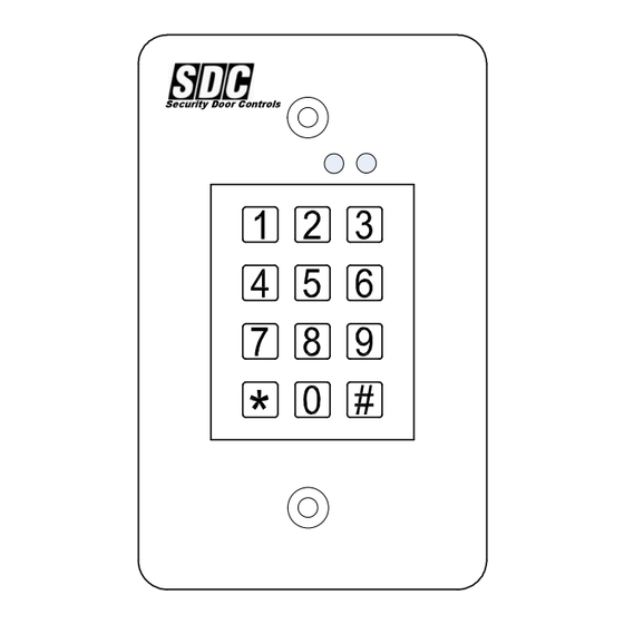
The 918 EntryCheck™ is a digital keyless entry system designed for
access control applications. The keypad is mounted on a rugged,
stainless steel faceplate and is designed to be mounted in a standard
single-gang electrical box. The indoor backlit keys have bright, easy-
to-read graphics.
Up to 500 entry codes, from 1 to 6 digits in length, can be programmed.
They can activate either, or both of the relay outputs. The "anti-
passback" feature prevents using the same code again before the
programmed time elapses.
All system indicators are long-lasting, solid state LEDs. Two indicators
show the status of the entry system. The left indicator lights red to
indicate power, then turns green when access is granted. The right
indicator lights yellow when the keypad is in "lockout" condition (from
too many incorrect code entries). The yellow LED flashes when the
keypad is in programming mode. An internal sounder beeps when each
key is pressed. An internal jumper sets the sounder volume high or low
The SENSE input can be used two ways. If programmed for "door
sense" the input is wired to a normally closed switch on the door to
detect when the door is opened or closed. Forced entry or door ajar
situations can then be detected. Using door sense, the "Auto-relock"
feature will prevent "tailgating" by turning off the Main Relay output
immediately when the door is closed after access has been granted. If
the SENSE input is programmed for "inhibit", the input can be wired to a
"service" switch or automatic timer that will disable the Main Relay when
required.
The REQUEST-TO-EXIT input can be wired to a pushbutton to provide
codeless activation of Main Relay, Auxiliary Relay, Output #3 or Output
#4 (programmable).
The ALARM SHUNT output activates when access is granted. This
output can be wired to shunt alarm contacts on the access door/gate to
prevent triggering of an alarm when authorized access occurs.
The 918 EntryCheck™ is powered from a 12-24V AC or DC source.
The EEPROM memory retains all entry codes and programming, even
without power. An internal jumper is provided to reset the master code.
The Main Relay has a 5 Amp capacity. The Auxiliary Relay has a 2
Amp capacity. Two solid state outputs, capable of switching 100 mA to
common, are programmable to signal forced entry, door ajar, lockout,
alarm circuit shunting, request-to-exit, and keypad active conditions.
P:\INSTALLATION INST\Access Controls\INST-918\INST-918.vsd
INSTALLATION INSTRUCTIONS
918 ENTRY CHECK
REV A
03-12
Page 1
®
Features
Keypad programmable
500 user codes
1 to 6 digit user codes
4 independent outputs
4 independent timers
2 Form C relay contacts
2 solid state open collector outputs
Program entry codes to activate one or
two relays
Disable input
Door sense input
Request-to-exit/enter input
Keypad tamper lockout
Timed anti-passback
Anti-tailgate
Two LED status indicators
Tactile key feel
Audible code entry verification
12 or 24V, AC or DC operation
SPECIFICATIONS
Mechanical
Dimensions: 3.00" W x 4.75" H x 1.50" D
(.250"D wall extrusion)
Electrical
Input Voltage: 12-24 Volts AC or DC
Operating Current: 30 mA typical, 150 mA max
Output Ratings
Main Relay: Form "C" 5 Amps @ 28 Volts max
Auxiliary Relay: Form "C" 2 Amp @ 28 Volts max
Type: Solid state outputs (Outputs #3 & #4)
Short-to-common 100 mA @ 24 VDC maximum
Environmental
Temperature: -22°F to 149°F (-30°C to 65°C)
Humidity: 5% to 95% non-condensing
Any suggestions or comments to this instruction or
product are welcome. Please contact us through
our website or email engineer@sdcsecurity.com
Advertisement
Table of Contents

Related Manuals for SDC 918 ENTRY CHECK


Summary of Contents for SDC 918 ENTRY CHECK
- Page 1 801 Avenida Acaso, Camarillo, Ca. 93012 • (805) 494-0622 • www.sdcsecurity.com • E-mail: service@sdcsecurity.com INSTALLATION INSTRUCTIONS ® 918 ENTRY CHECK The 918 EntryCheck™ is a digital keyless entry system designed for access control applications. The keypad is mounted on a rugged, Features stainless steel faceplate and is designed to be mounted in a standard single-gang electrical box.
- Page 2 QuickStart Programming To enter Programming Mode, enter #9# plus the Master Code. The yellow indicator will blink slowly showing that the 918 EntryCheck™ is in programming mode. Use the option codes to program the each function. After the new data entry is complete for each function , the yellow indicator will flash quickly while the data is being stored and the green indicator will light briefly if the programming has been accepted.
-
Page 3: Keypad Wiring
KEYPAD WIRING See Fig. 3 for an example of a basic door installation. The keypad is mounted adjacent to the door. An electric door strike is mounted in the door jamb to release the door lock. A magnetic switch is mounted on top of the door jamb for detecting when the door is open. -
Page 4: Factory Defaults
Programming the 918 To Hold the Output Re-entering a Command After a Mistake SDC’s EntryCheck™ products have a programmable “Toggle If the red indicator lights, signaling an incorrect entry, or an Mode” available for each relay and solid-state output. When an... - Page 5 (Typical Programming cont.) Select Keypad Lockout Output Default: No Output Program all normal entry codes to use the Main Relay (Relay #1), and only Relay #1 as the output relay. Program the code(s) Sets which output activates when the keypad is “locked out” after that you want to use to hold the output for an indefinite period to too many incorrect entry code attempts.
-
Page 6: Resetting Keypad
Selects mode for Keypad LED Backlight Default: 30 Seconds Solid-state Output #4 On-time Default: 60 Seconds Selects whether or not the keypad back light stays OFF, lights for 30 Sets the length of time Output #4 activates when triggered. seconds when activated or stays ON. Press: 2 4 # Seconds # Press: 52 # Output # Seconds=Output time in seconds (0-60), 99=Toggle Mode...
Need help?
Do you have a question about the 918 ENTRY CHECK and is the answer not in the manual?
Questions and answers