Table of Contents
Advertisement
Quick Links
801 Avenida Acaso, Camarillo, Ca. 93012 • (805) 494-0622 •
www.sdcsecurity.com • E-mail: service@sdcsecurity.com
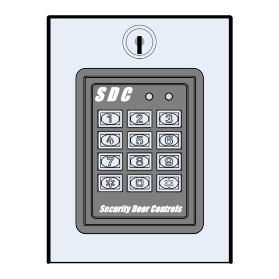
The EntryCheck™ 926 Outdoor Keypad is a digital keyless entry system
designed for access control applications. It is ideal for controlling doors or
gates. The backlit keys are bright and easy-to-read. A heavy cast vandal-
resistant housing design with allows the 926 to be surface-mounted on a
wall or pedestal post. The keypad electronics are secured by an integral
keylock switch and may be monitored with the built-in tamper switch.
The 926 has a capacity of 500 users. Users can be assigned to use 4 to 6
digit PIN codes. An authenticated access can be programmed to activate
one or both of the onboard relay outputs.
The timed "anti-passback" feature prevents using the same credentials
twice before a programmed waiting period has elapsed.
Two long lasting solid state LED indicators show the status of the system.
The left bi-color indicator lights red to indicate power, then solid green when
a relay is active (access grant, etc.). The right indicator flashes yellow to
indicate that the keypad is in programming mode.
An internal sounder can be programmed to beep each time a key is
pressed or when an output is activated. An internal jumper sets the
sounder volume high or low.
The SENSE input can be configured two ways through programming .
When configured for "Door Sense", the input is wired to a normally closed
door position switch to detect when the door is opened or closed. Forced
entry or door ajar situations can then be detected. The "Auto-relock" feature
can also be used to turn off the Main Relay output immediately when the
door is closed after access has been granted to prevent "tailgating".
When the SENSE input is configured for "Inhibit", the input can be wired to
a normally open "service" switch or automatic timer that will disable access
while the switch is closed.
A REQUEST-TO-EXIT input can be wired to a normally open pushbutton or
wireless switch to provide codeless activation of the Main Relay, Auxiliary
Relay, Output #3 or Output #4 (user programmable).
The ALARM SHUNT signal is available when access is granted. This
signal can be programmed to activate any of the relays or solid state
outputs to shunt alarm contacts on the access door/gate preventing the
triggering of an alarm when an authorized access occurs.
The 926 EntryCheck™ is powered from a 12 or 24V AC or DC source. The
non-volatile EEPROM memory retains entry codes and programming when
power is removed. An internal jumper is provided to reset the master code.
The Main Relay has a 5 Amp capacity. The Auxiliary Relay has a 2 Amp
capacity. Two solid state outputs, capable of sinking 100 mA to common
are programmable for alarm shunting, or to signal forced entry, door ajar,
keypad lockout, request-to-exit, and keypad active conditions.
P:\INSTALLATION INST\Access Controls\INST-926\INST-926.vsd
INSTALLATION INSTRUCTIONS
926 EntryCheck
Rev -
01-18
Page 1
TM
FEATURES
Keypad programmable
500 user codes
4 to 6 digit user codes
4 independent outputs
4 independent timers
2 Form C relay contacts
2 solid state open collector outputs
Program entry codes to activate 1 or 2 relays
Disable input
Door sense input
Request-to-exit input
Keypad tamper lockout
Timed anti-passback
Anti-tailgate
Two LED status indicators
Tactile key feel
Audible code entry verification
12V or 24V, AC or DC operation
Integral keyswitch lock w/ 2 keys
Integral Anti-tamper switch
SPECIFICATIONS
Mechanical
Dimensions: 4-3/4" W x 6-3/8" H x 4-1/2" D
Electrical
Input Voltage: 12/24 Volts AC or DC
Operating Current: 30 mA typical, 150 mA max
Output Ratings
Main Relay: Form "C" 5 Amps @ 28 Volts max
Auxiliary Relay: Form "C" 2 Amp @ 28 Volts max
Type: Solid state outputs (Outputs #3 & #4)
Short-to-common 100 mA @ 24 VDC maximum
Environmental
Temperature: -4°F to 140°F (-20°C to 60°C)
Humidity: 5% to 95% non-condensing
Advertisement
Table of Contents

Related Manuals for SDC 926 EntryCheck


Summary of Contents for SDC 926 EntryCheck
- Page 1 Output Ratings Main Relay: Form “C” 5 Amps @ 28 Volts max The 926 EntryCheck™ is powered from a 12 or 24V AC or DC source. The Auxiliary Relay: Form “C” 2 Amp @ 28 Volts max non-volatile EEPROM memory retains entry codes and programming when Type: Solid state outputs (Outputs #3 &...
- Page 2 QuickStart Programming You must first enter programming mode to perform any function. The yellow indicator will blink slowly showing that the 926 EntryCheck™ is in programming mode. Use the option codes to program each function. After the new data entry is complete for each function , the yellow indicator will flash quickly while the data is being stored and the green indicator will light briefly if the programming has been accepted.
- Page 3 KEYPAD WIRING KEYPAD POWER BLACK Refer to the wiring diagram shown in Fig. 4 to assist in the wiring. 12 or 24 VOLTS TO POWER SUPPLY AC OR DC Note: Relays are for Low Voltage applications only. For lock power, use BRN/YEL 18 AWG wire or larger (depending on load).
- Page 4 When an output is programmed for Toggle Mode, the output alternates from OFF to ON or from ON to OFF each time it is When the 926 EntryCheck™ is in Programming Mode the yellow accessed. When an output is toggled on, the green LED remains indicator will blink slowly.
- Page 5 Select Keypad Lockout Output Default: No Output Erasing All Entry Codes Sets which output activates when the keypad is “locked out” after WARNING: PERFORMING THIS COMMAND WILL REMOVE too many incorrect entry code attempts. The lockout time is 60 ALL ENTRY CODES FROM THE MEMORY seconds.
- Page 6 Solid-state Output #3 On-time Default: 02 Seconds Keypad Lockout Count Default: 3 Attempts Sets the length of time Output #3 activates when triggered. Sets the number or incorrect entry code attempts allowed before the keypad “locks out” for 60 seconds. Press: 23 # Seconds # Press: 50 # Attempts # Seconds=Output time in seconds (1-60), 99=Toggle Mode...
- Page 7 Mounting Use the provided enclosure holes to mount the 926 keypad to a wall, pilaster or gooseneck pedestal . Use supplied hardware or other appropriate hardware suitable for your specific mounting post surface. Clean any debris out of the enclosure that may cause a short. If the keypad is used to activate a gate operator, mount the keypad a minimum of 6' from the gate and gate operator to avoid contact with the movement of the gate upon activation.
Need help?
Do you have a question about the 926 EntryCheck and is the answer not in the manual?
Questions and answers